How to test a capacitor without soldering it. How to check the health of the capacitor, its capacitance and resistance.
Checking capacitors with a digital multimeter

As already mentioned, it is possible to reliably check the health of a capacitor only with the help of a device that is able to measure its capacitance. As a rule, inductance and capacitance meters (LC meters) are used for these purposes. They are quite expensive.
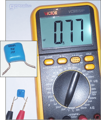
But, despite this, you can find an affordable multimeter with the function of an LC meter. For example, I have a Victor VC9805A+ multitester in my workshop.
It has 5 measurement limits and is able to detect capacitance in the range from 20 nanofarads (20nF) to 200 microfarads (200μF). With it, you can measure the capacitance of both conventional non-polar capacitors and polar electrolytic ones.

20nF (20nF)
200nF (200nF)
2µF (2µF)
20µF (20µF)
200uF (200μF)
The maximum measurement limit is limited to 200 microfarads (uF), which is not so much, considering that the capacitance of electrolytic capacitors sometimes reaches 10,000 uF.
Measuring probes of the device are connected to the capacitance measurement sockets (denoted as Cx). In this case, the polarity of their connection must be observed.

Capacitance measurement connector (Cx)
The photo shows the process of measuring the capacitance of a 100nF (0.1 uF) capacitor. A limit of 200 nanofarads was chosen for measurement.

As you can see, the capacitance corresponds to the one indicated in the marking on the case - 104.7nF. The capacitor is correct.
And here is an example of a faulty metal-film capacitor K73-17 at 100nF. I discovered it quite by accident, I thought that it was completely serviceable.
I will only note that initially I checked this capacitor with a multimeter in ohmmeter mode. Then I did not find anything suspicious. In fact, it turned out to be faulty, had a very small capacity, only 737 picofarads.
In the next photo, checking the same capacitor with a universal tester.

That is why it is worth using a tester with a capacitance measurement function to test capacitors. This will give the most reliable result.
An exception may be an electrical breakdown, which is easy to detect with an ohmmeter, and sometimes purely visually during an external examination. Here is an example.
The photo shows a punched non-polar capacitor for an operating voltage of 1.2kV.
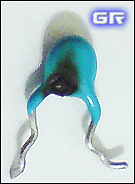
With a significant excess of the operating voltage on the capacitor, an electrical breakdown occurs between its plates. On the case of pierced capacitors, you can find dark spots, swellings, dark spots and others. external signs element damage.
The case may be split or have chips and cracks on the surface.
Electrical breakdown of the capacitor in electronic circuit converter can cause damage to the compact fluorescent lamp. I mentioned this on the page about the device of CFL lamps.
It is worth noting the fact that breakdown in aluminum electrolytic capacitors is quite rare. The reverse situation is observed with tantalum capacitors, which, due to their characteristics, do not withstand even a slight excess of the operating voltage.
When measuring the capacitance of an electrolytic capacitor, it is worth knowing one feature. Since their tolerance is very large, sometimes reaching 30%, the scatter in the capacitance value can be quite decent. In this case, the capacitor should not be considered unusable. In addition, a lot depends on what device you use.
Here is a list of the actual capacitance of the new capacitors. The measurements were carried out with a universal tester LCR-T4:
2200μF (35V) - real 2155μF (Jamicon);
470µF (25V) - real 420.9μF(EPCOS);
220µF (400V) - real 217.7µF (SAMWHA);
100 μF (450V) - real 98.79μF (Jamicon);
100 μF (400V) - real 101.1μF (SAMWHA);
82 μF (400V) - real 75.65μF (Jamicon);
82 μF (450V) - real 77.46μF (SAMWHA);
82 μF (450V) - real 77.05μF (CapXon);
68 μF (450V) - real 66.43μF (Jamicon);
33 μF (160V) - real 31.99μF (SAMWHA);
22 μF (250V) - real 22.21μF (SAMWHA);
As you can see, the EPCOS B41828 105 0 C 470μF (M) 25V capacitor turned out to be the poorest quality.
The same capacitors were tested with a Victor VC9805A+ multimeter. So, he showed the capacitance of the capacitors is less. For a 220μF (400V) conduit, he generally measured 187μF!
A malfunction of the electrolytic capacitor can be determined by external examination. If its body has a break in the notch in the upper part of the body - 100% it must be changed. The rupture of the protective notch on the case indicates that an overvoltage acted on the capacitor, as a result of which the so-called "explosion" occurred.
As already mentioned, the breakdown of aluminum electrolytic capacitors is a rather rare phenomenon. Instead, there is such an "explosion" or "bloating". This comes from the fact that when the permissible voltage is exceeded or when the polarity is reversed, a storm begins in the capacitor. chemical reaction. It leads to heating and evaporation of the electrolyte, the vapors of which press on the walls of the housing and break the protective valve.

"Exploded" electrolytic capacitor
Such defects in capacitors appear, for example, when a powerful electric discharge is applied to electronic device during a thunderstorm or strong power surges in the 220V electric lighting network.
A similar effect of "bloating" of an aluminum electrolytic capacitor is also manifested during its long-term operation. Since the electrolyte is liquid, it tends to evaporate during heating and long-term operation.
It is worth noting that the condenser heats up not only from the outside, but also from the inside. This is due to the presence of equivalent series resistance (ESR). When the electrolyte evaporates, the capacitance of the capacitor decreases markedly. As time goes by, it swells up more and more. About such a capacitor they say that it is dry.
When repairing electronic equipment, sometimes it happens that in the power supply unit that has served for more than a year of the device, you can find a whole garden of such "pouffers".
Loss of capacity can cause damage to the TV. Such a failure is not uncommon. I have already talked about one of them.
IN modern conditions, when there is a widespread use of impulse technology, another important parameter one thing to consider when testing electrolytic capacitors is its ESR. The site has a table with the ESR values of new capacitors of different capacities. I advise you to take a look.
Since most multimeters do not support the ESR measurement function, it is better to purchase a specialized tester or a universal radio component tester if necessary. This is an indispensable device in the workshop of a radio amateur and any radio mechanic.
Precautions when testing electrolytic capacitors.
When checking an electrolytic capacitor, it is necessary unload it completely! Especially this rule should be followed when checking capacitors with a large capacity and high operating voltage. If this is not done, the meter can be damaged by high residual voltage.
For example, it is often necessary to check the health of capacitors that are used in switching power supplies. Their capacity and operating voltage are large enough and, if not fully discharged, can lead to damage to the multimeter.
Therefore, before checking, they must be discharged by short-circuiting the leads (for low-voltage capacitors with a small capacity). You can do this with a regular screwdriver.
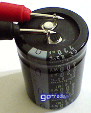
Electrolytic capacitor with a capacity of 220 microfarads and an operating voltage of 400 volts
It is advisable to discharge capacitors with a capacity of more than 100 microfarads and an operating voltage of 63V through a resistor with a resistance of 5-20 kilo-ohms and a power of 1-2 watts. To do this, the terminals of the resistor are connected to the terminals of the capacitor for a few seconds to remove the residual charge from its plates. The discharge of a capacitor through a resistor is used in order to eliminate the appearance of a powerful spark.
When carrying out this operation, you should not touch the terminals of the capacitor and resistor with your hands, otherwise you can get an unpleasant electric shock when the plates are discharged. It is better to clamp the resistor with pliers in insulation and even then connect it to the terminals of the capacitor.
When shorting the terminals of a charged electrolytic capacitor, a spark jumps, sometimes very powerful.
Therefore, care should be taken to protect the face and eyes. If possible, use safety goggles or keep away from the capacitor when carrying out such work.
Checking capacitors with an ohmmeter.
The most accessible and common device with which you can test a capacitor is a digital multimeter switched on in ohmmeter mode.
Since the capacitor does not pass direct current, the resistance between its terminals (plates) must be very large and limited only by the so-called leakage resistance. In a real capacitor, the dielectric, despite the fact that it is an insulator, still passes a small amount of current. Usually, this current is very small and is not taken into account. It is called leakage current.
This method is suitable for testing non-polar capacitors. They have an infinitely large leakage resistance, and if you measure the resistance between the terminals of such a capacitor with a digital multimeter, the device will record an infinitely large value.
Usually, if a capacitor has an electrical breakdown, then the resistance between its plates is quite small - a few units or tens of ohms. A broken capacitor, in fact, is an ordinary conductor.
In practice, you can check for breakdown of any non-polar capacitor as follows:
We switch the multimeter to the resistance measurement mode and set the largest of possible limits. For digital multi tester series DT-83x, MAS83x, M83x, this will be the limit 2M(2000k), that is, 2 megaohms.
Next, we connect the measuring probes to the terminals of the tested capacitor. If it is working, then the device will not show any value and the unit will light up on the display. This indicates that the leakage resistance is more than 2 megohms.
This is enough to judge the health of the capacitor in most cases. If the DMM clearly detects any resistance that is less than 2 megaohms, then most likely the capacitor has a large leak.
It should be noted that it is impossible to hold the terminals of the capacitor and the metal probes of the multimeter with both hands when measuring! In this case, the device will record the resistance of your body, and not the resistance of the capacitor. Since the resistance of the human body is less than the leakage resistance, the current will flow along the path of least resistance, that is, through your body along the path hand - hand. The measurement result will be incorrect. About it simple rule It is worth remembering when checking other radio components.
Checking polar electrolytic capacitors with an ohmmeter is somewhat different from checking non-polar ones.
The leakage resistance of polar capacitors is usually at least 100 kiloohm. For higher quality capacitors, this value is at least 1 megaohm.
When checking such capacitors with an ohmmeter, you must first discharge them by short-circuiting the leads. If this is not done, then there is a risk of burning the multimeter.
Next, you need to set the resistance measurement limit to at least 100 kiloOhm. For the capacitors mentioned above, this will be the limit 200k(200000 ohms). Further, observing the polarity of connecting the probes, measure the leakage resistance.
Since the electrolytic capacitor has a rather large capacitance, it will begin to charge when tested. This process takes a few seconds, during which the resistance on the digital display will increase - the readings on it will increase. This will continue until the capacitor is fully charged. If the value of the measured resistance has exceeded 100 kiloOhm, then in most cases it is possible to judge with sufficient confidence that the element under test is in good condition.
One of the common malfunctions of electrolytic capacitors is a partial loss of capacitance. In such cases, its capacity is noticeably less than indicated on the case. It is difficult to determine such a malfunction with an ohmmeter. I would say it's impossible. To accurately detect a failure such as loss of capacitance, you will need a capacitance meter, which is not available in every multimeter.
Also, using an ohmmeter, it is difficult to detect such a capacitor malfunction as an open circuit.
For polar electrolytic capacitors, an indirect sign of a break may be the absence of a change in the readings on the multimeter display when measuring resistance.
For non-polar capacitors of small capacity, it is almost impossible to detect a break, since a good capacitor has a very high resistance. The charge of the capacitance of such a capacitor passes very quickly and because of this it is impossible to determine whether the capacitor has at least some capacitance. On the display of the multimeter, the readings will not change, as happens when a capacious electrolytic capacitor is charged.
As you already understood, it is possible to detect an open in a non-polar capacitor only with the help of a capacitance measuring device.
In practice, a break in capacitors is quite rare, mainly this happens with mechanical damage. Much more often when repairing equipment, it is necessary to replace capacitors that have an electrical breakdown or a partial loss of capacitance.
Checking the capacitor with an ohmmeter.
Earlier, when pointer ohmmeters were common among radio amateurs, capacitors were checked in a similar way. At the same time, the capacitor was charged from the battery of the ohmmeter and the resistance indicated by the arrow of the device grew. Ultimately, its value reached the value of the leakage resistance.
According to the speed of the deflection of the arrow measuring device from zero to the final value, the capacitance of the electrolytic capacitor was also evaluated. The longer the charge took (the longer the arrow of the device deviated), the larger the capacity, respectively. For capacitors with small capacity(1 - 100 microfarads), the arrow of the measuring device deviated quickly enough, which indicated a small capacity, but when checking capacitors with a capacity of 1000 microfarads or more, the arrow deviated much more slowly.
Checking capacitors with an ohmmeter is indirect method. A more accurate and truthful assessment of the health of the capacitor and its parameters allows you to get a multimeter with the ability to measure electrical capacitance.
At the moment, almost everyone can face a capacitor failure. To determine its serviceability, you do not need to study the basics of electrical engineering. It will be enough just to know how to check the capacitor with a multimeter.
Thanks to this, you can restore the functionality of the microwave or refrigerator. Before repairing, it is necessary to determine which part is defective. A digital multimeter is great for testing a capacitor.
How to measure capacitance
During the test, you need to remember that not all faults will be tested in ohmmeter mode. If the multimeter shows an infinitely high resistance of the polar element, then this will be considered a sign of its malfunction. Check Loss nominal capacity in ohmmeter mode you will not succeed. To measure this characteristic, you must use a digital multimeter. This device will help you test in the range from 20 nF to 200 microfarads.
Thanks to multimeters with a similar function, it will be possible to test any capacitors, even electrolytic ones. If you wish to test an electrolytic capacitor, then the polarity must be observed.
![]()
In the photo above, you can see that in order to check the capacitance of the capacitor, it is necessary to insert the output parts into the sockets Cx, and the handle must be set to the position of the required measurement range. After that, all capacity parameters will be displayed on the display.
Main malfunctions and their causes
It doesn't matter what type of capacitor you use. Any capacitor can fail due to the following problems:
- The reduction in nominal capacity that will occur during the drying process.
- The leakage current will exceed the required value.
- Increase in active losses of the circuit.
- There was a short circuit of the plates.
- Loss of contact that has occurred between the lining and the output of the part.
All the malfunctions that we described above can most often result from a violation temperature regime or exceeding the allowable voltage threshold. Experts assure that by lowering the operating temperature, it is possible to significantly extend the service life of the radioelement.
In practice, most often a capacitor failure can be caused by a short circuit. Now we decided to talk in detail about how to diagnose a capacitor.
Troubleshooting
It is also possible to identify a breakdown of the capacitor due to visual inspection. If a breakdown occurs, then cracks or swelling may form on the capacitor. In the photo below you can see signs of a breakdown of the capacitor.

In most cases, it is not always possible to detect a breakdown during a visual inspection. If appearance parts is really normal, then the problem may have occurred due to an internal short circuit. Before you start checking a non-polar film, ceramic, electrolytic, smd or sbb capacitor with a multimeter, you will need to remove it from the board. Soldering the capacitor is not always necessary. In some cases, you can check the resistance of the circuit directly on the board. But you need to remember that this will require a resistance map.
Carrying out diagnostics for non-polar devices
To check the device with a multimeter, you do not need to measure the capacitance of a non-polar type capacitor. In this case, it will be enough to simply measure its resistance. It must necessarily be infinitely large. If a breakdown occurs, then the multimeter will show a negligible value. For testing, you will need to perform the following algorithm of actions:
- You should set the maximum measurement mode in the ohmmeter mode.
- With the probes of the device, you will need to touch the terminals of the radio component.
- If you see the number "1" on the display, then this will indicate that the resistance will be more than 2 megaohms. If the multimeter shows a different value, then in this case a short circuit has occurred.
It is important to know! During measurements, remember that you can not hold the probes of the device by non-isolating the place. In this case, the testimony may simply be unreliable.
If necessary, you can also test in the diode test mode. If in this case there is a breakdown, then the multimeter will emit a characteristic signal. Here you can also use the calculator for.
Diagnostics of polar capacitors
It is necessary to check polar type capacitors in a similar way. The only feature is that the measurement threshold must be greater than 100 com. Before carrying out diagnostics, you will need to discharge the radio component. To do this, you can simply connect the conclusions. If you are using high voltage capacitor, then it must be "short-circuited" through the load.
If you do not remove the charge, then you can ruin the multimeter. In addition, you should remember that if you touch one of the leads to the body, then you can conduct a discharge through yourself. If during discharge you see sparks, then this will indicate that the device is working properly.
To check the capacitor with a multimeter, you must connect the probes. As a result electricity, which comes from the instrument will accumulate in the tested part. If the multimeter shows an increase in resistance, then this indicates serviceability. This process can be studied in most detail in analog measuring instruments.

The test method in ohmmeter mode is considered indirect. To obtain a more accurate estimate, you must use a digital multimeter. You can use the DT890B+ multimeter to take the measurement.
Repair of household appliances
If the capacitors fail, then, respectively, and Appliances gradually ceases to function. Our tips will help you simply determine the health of the capacitor. After the analysis, it is necessary to replace the capacitor and the equipment will work again.
Before starting repairs household appliances you need to make sure that they are disconnected from the power supply. Now you know how to check the capacitor with a multimeter with your own hands. We hope this information was useful and interesting.
This article will discuss how to check a capacitor with a multimeter, if you do not have a device that checks the capacitance of capacitors - an LC meter.
There are two types of capacitor: polar (electrolytic capacitors), and non-polar, to which all the rest can be attributed. Polar-type capacitors got their name due to the fact that they are soldered to radio equipment in a strict order: the positive contact of the capacitor to the positive contact of the circuit.
In case of violation of the polarity of such a capacitor, it can fail, up to explosion.
Imported capacitors are located on their upper part with a small cross or other figure that is pressed into the case. In these places, the body is thinner.

This is done to ensure safety. For this reason, if there is an explosion imported capacitor, then simply open its upper part. In the image you can see a swollen capacitor from the computer motherboard. The break was made exactly along the line.

Checking the capacitor with a multimeter
To check the capacitor with a multimeter, you need to follow one rule - the capacitance of the capacitor should not be less than 0.25 uFarad.
Before you check the capacitor with a multimeter, you should determine its polarity. To determine the polarity of the capacitor, it is enough to carefully look at its case, it must be marked. The designation of the minus is made with a tick. A black check mark drawn over a bold gold stripe and a negative terminal pointer.

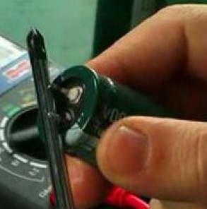
Now, you should take a multimeter, and set the toggle switch to the continuity mode (or to resistance) and touch the contacts with the probes. Since the multimeter in the continuity and resistance measurement mode produces a constant voltage, the capacitor will be charged and, as it charges, the resistance of the capacitor will increase.
While charging, the resistance value increases until it becomes too large. Let's see how it should look.

Here only the contacts are touched with the help of probes.

We continue to hold and watch the resistance grow

until it's too big
It is convenient to check the capacitors with an analog multimeter, since it is easy to track the turn of the arrow in it, about the non-blinking numbers in the digital multimeter.

If, while touching the probes of the capacitor, the multimeter beeps and shows zero, then this says short circuit in the condenser. If the multimeter immediately shows one, then there is a break in the capacitor. In any of the situations described, the capacitor should be thrown out, since it is not working.
Checking non-polar capacitors is easier. We set the toggle switch of the multimeter to megaohms and press the probes to the terminals of the capacitor. If the resistance value does not reach 2 MegaOhm, then the capacitor can be considered faulty.
Test capacitor tester video
Well, that's all, now you know how to check the capacitor with a multimeter. If you need to check a capacitor with a capacitance of less than 0.25 microfarads, you will have to use a special device.
How to test a capacitor with a tester? This question arises for everyone who at least sometimes picks up a soldering iron. Checking the capacitor with a tester is very simple, but first you need to make a reservation that:
- By tester, I mean the good old dial tester, not a digital multimeter.
- Only relatively large capacitors can be tested.
- It will not be possible to find out even the approximate capacitance of the capacitor.
To check the capacitor with a tester, you must set the tester to the resistance measurement mode and try to measure the resistance of the capacitor. With a relatively large capacitance of the capacitor (from about 1 μF), if the capacitor is in good condition, we will see that the tester needle deviates and then starts to drop to infinity. This indicates that the capacitor was discharged, then we charged it from the tester and, as it charged, it stopped conducting current. Then you can swap the capacitor leads (or tester probes) and look at its resistance again. This time we will see that the arrow has deviated much more than the first time. This happened because the capacitor was charged and we connected it to the tester in such a way that the direction of the capacitor discharge current coincided with the direction of the current through the tester. Everything will be like the first time. After the discharge, the capacitor will begin to charge with a different polarity and again cease to conduct current. All this suggests that the capacitor has a capacitance.
The intensity of the charge-discharge will depend on the capacitance of the capacitor. The higher it is, the more the arrow of the tester will deviate and the process of charging and discharging the capacitor will be slower. At small containers capacitors, you may not even notice the deviation of the arrow during the first measurement. Only after charging the capacitor and measuring its resistance when changing the polarity, you can notice a slight twitching of the arrow. The smaller the capacitance of the capacitor, the greater the resistance it is necessary to install the device. If the arrow does not deviate in either the first or second case and the capacitance of the capacitor is more than hundreds of picofarads (it is difficult to determine the exact limit), then most likely the capacitor is faulty.
Another option for testing a capacitor is a breakdown test. This is when the capacitor begins to conduct current. This happens if you apply a voltage to the capacitor higher than that for which it is designed. If the capacitor is broken, we will see its constant resistance. This also indicates that it is defective.
How to test a capacitor with a multimeter
How to test a capacitor with a multimeter? This question arises even more often than about checking by a tester, because. Basically, digital multimeters are now used as a desktop measuring instrument. To test for a breakdown is as simple as with a tester. And to check for capacity - perfect option if the multimeter has a capacitance measurement function. If not, then it is difficult to use it for such an operation. The fact is that everything described above can be done by him, but on a multimeter it is difficult to understand what it shows if the readings change. And they don’t just change, we don’t even know exactly what measurement limit to set the device to. So, by by and large, check the capacitor for operation with a multimeter, of course, it is possible, but it is very inconvenient. In general, the good old arrow taxis.
The cause of electrical breakdown is often the failure of the capacitor. To carry out repairs, you need to know how to check the capacitor with a multimeter. Of the tools, you will still need a soldering iron, since the part will have to be soldered from the board.
Polar capacitors are easy to check in ohmmeter mode. If the resistance of the part is infinitely large (one is on in the left corner), this means that a break has occurred.
Capacitor capacitance testing
An electrolytic capacitor dries out over time and its capacitance changes. To measure it, you need special device. How to test an electrolytic capacitor with a multimeter? The device is connected to the part, and the required measurement limit is selected by the switch. 
When an overload signal appears on the indicator, the tool switches to a lower accuracy. Similarly, the capacitance of non-polar capacitors is measured.
Types of capacitor faults
- The capacity has decreased due to drying out.
- Increased leakage current.
- Increased active losses in the circuit.
- Breakdown of insulation (short circuit of the plates).
- A break inside between the lining and the output.
Visual inspection of capacitors
Malfunctions occur due to mechanical damage, overheating, power surges, etc. Most often, a capacitor fails due to breakdown. It can be seen by the following defects: darkening, swelling or cracks. For domestic parts, when swollen, a small explosion may occur. Foreign capacitors are protected from it by a cross-shaped slot at the end of the part, where a slight swelling occurs, visible to the eye. A part with this malfunction may have a normal appearance, but be inoperative.
To check the element is unsoldered from the board, otherwise it is impossible to test it. The check can be done using the resistance map on the board, but for a specific model it is not always at hand, even during service.
Troubleshooting Non-Polar Capacitors
The resistance of a non-polar capacitor is measured. If it has a value of less than 2 mΩ, there is a malfunction (leakage or breakdown). A good part usually shows a resistance of more than 2 mΩ or infinity. When measuring, do not touch the probes with your hands, since the resistance of the body will be measured.
Breakdown testing can also be done in diode test mode.
A break in capacitors of small capacity cannot be detected by an indirect method. How to check the capacitance of a capacitor with a multimeter in a similar situation? Here you need a device where there is a necessary function. 
Checking electrolytic capacitors
There are slight differences, how to check the capacitor with a multimeter in ohmmeter mode. Polar capacitors are checked in a similar way, but their measurement threshold is 100 kOhm. As soon as the device is charged and the reading exceeds this value, it can be judged that the part is working.
Important! Before checking the performance of the capacitor with a multimeter, it should be discharged by connecting the leads. High-voltage parts from power supplies are connected to an active load, for example, through an incandescent lamp. If the charge is left, you can damage the device or get a noticeable discharge by touching the leads with your hands.
Probes are connected to the capacitor, showing an increase in resistance in a serviceable part. The black probe with negative polarity is connected to the negative conductor, and the red probe to the positive one. On the surface of an electrolytic capacitor, minus is indicated by a white stripe on the side. 
On pointer instruments, it is more convenient to carry out such a check, since the capacitance value can be judged by the speed of movement of the pointer. You can test good parts with known values and compile a table that approximates capacitance from voltage drop rate readings.
After the capacitor is charged during testing (usually up to 3 V), the voltage value is measured on it. If it is 1V or less, the part needs to be replaced because it is not charged. After checking, a serviceable capacitor is soldered back, but it must first be discharged by shorting the legs with a probe.
The guarantee for an electrolytic capacitor means that for a given time, the value of its capacity will not go beyond the specified limits, usually not exceeding 20%. When the service life is exceeded, the part remains operational, but its capacitance value is different, and it must be controlled. How to check the capacitor with a multimeter in this case? Here, the capacitance is measured with a special device.
A break is difficult to detect with an ohmmeter. Its sign is the absence of a change in readings in the ohmmeter mode.
How to test a capacitor with a multimeter without soldering
The difficulty of checking the capacitor without dismantling lies in the fact that elements such as transformer windings or inductances with low resistance are adjacent to it. direct current. Measurements can be made in the usual way when there are no low-resistance parts nearby. 
Conclusion
The home master should know how to check the capacitor with a multimeter. There are direct and indirect methods for this. Do not forget about the need to discharge the capacitor before each measurement.
 (1 ratings, on average: 5,00 out of 5)

