Marking of imported capacitors by color. Capacitor markings - types and descriptions of decodings
Theirs is more complicated. Usually the following information is applied to the capacitor body:
Nominal capacity;
Rated (maximum permissible) voltage;
TKE (temperature coefficient of capacitance).
Tolerance and TKE are indicated only for “good” capacitors, i.e. film, ceramic and mica; for polar capacitors, these two parameters are so huge that they are not even indicated. In “vital” places, polar devices can only be used to filter the supply voltage.
Let's start with domestic non-polar capacitors. For capacitors with a capacity of up to 100 pF, the parameters on the case are most often not indicated at all. I don’t know what this is connected with, perhaps it’s a pity for manufacturers to waste paint on such “small things.” The capacitance of such capacitors can only be determined indirectly by measuring their Xc at some precisely known frequency f and substituting this data into the formula:
where U reH is the output AC voltage generator, V; 1 s - current through, mA; f reH - , kHz; C is the capacitance of the capacitor, pF; 2π « 6.28. The range of capacitances of “colored” capacitors is indicated in table. 3.3. These are taken from the article by A. Perutsky, Radiomir, No. 8, 2003, p. 3.

But on some capacitors of this capacity and on most capacitors of larger capacity, the parameters are indicated. The capacity is designated by numbers, the letter “p” (according to the old standard - “P”) means “picofarads”, “p” (“N”) - “nanofarads”, “μ” - “microfarads”. The capacity is encrypted in the same way as , i.e. "47H" means 47 nF (0.047 µF), and "H47", or "470r" - 470 pF (0.47 nF). If the capacitance of a capacitor is expressed in picofarads, then the letter “p” or “P” is usually not drawn on its body, i.e. if the capacitor says “1000” without any additional identification marks, then its capacitance is 1000 pF.
The approximate capacitance of film and mica capacitors can be determined by the size of their case: the larger the capacitance at the same maximum permissible voltage, the larger size housings. As the maximum permissible operating voltage increases, the dimensions of the capacitor also increase. U ceramic capacitors Different capacitances use different dielectrics with different dielectric constants, so two capacitors of the same size can differ in capacitance by hundreds...thousands of times. But the more the dielectric constant dielectric used, i.e., the smaller the ratio “surface area of the capacitor x its capacitance”, the higher the internal . Therefore, it is undesirable to use ceramic ones to filter high-frequency interference and ripple in power buses and other circuits through which significant high-frequency current flows. Mica ones are ideal, but they are “large” and expensive, so in such chains it is better to use film ones.
The tolerance for capacitors is within 5...20%, and it is indicated by the same letters (they are always capitalized - “large”) as for resistors. Moreover, if the container is marked with Latin letters (p, p, m), then the tolerance is marked with Latin letters. By the way, Russians mark their parts with a 5% tolerance with the letter “I”, and all other countries with the letter “J”.
TKE for capacitors is most often insignificant, but in some devices (masters) it is desirable that it be equal to zero. It arises due to the fact that when the capacitor is heated, its dielectric expands very slightly, the distance between the plates increases, because of this the capacitance of the capacitor decreases. That is, such a capacitor has a negative TKE. There are also those with positive TKE. This coefficient is maximum (in modulus) for ceramic capacitors, and the larger the capacitance of the capacitor, and its smaller dimensions, the greater the TKE. For film capacitors, TKE is extremely small (and usually negative), while for mica capacitors it is practically zero.
You can find out how much the capacitance of the capacitor changes when the temperature changes using the formula:
![]()
where C is the capacitance of the capacitor at the initial temperature; C D1 is the capacitance of the capacitor when the temperature changes by At (in degrees Celsius or Kelvin).
Dividing by a million is mandatory - TKE is an extremely small value, and if it is not multiplied by this number before applying it to the capacitor body, there will be too many zeros after the decimal point.
TKE for all capacitors is standardized and can be equal (according to the domestic standard it is designated on the capacitor body as “MPO”, according to the European standard - “NPO”, “COG”, “SON”, “CH” - this is the same thing); -47 (M47 - according to the old domestic standard; on the housings of domestic capacitors, the rating and tolerance of which are indicated in Latin letters, it is indicated by the letter “U”); -75 (M75, “M”); -750 (M750, N750 - European standard, “T”); -1500 (M1500, “V”); +100 (P100). For high-capacity capacitors (ceramic, more than 0.01 μF), TKE is very large and under the influence of temperature, the capacitor capacity can change by 30% (NCO, “D”, X7R, X7V), 70% (H70) or 90% (H90 , "F"); at imported capacitors maximum change in capacitance - 50% (Y5V, Z5U) when the temperature changes by 50...80 °C.
Also, the capacitance of ceramic capacitors changes under the influence of voltage. For Y5V capacitors, as the voltage increases from 5 to 40 V, the capacitance decreases by 70%.

Rice. 3.27. Explanation of capacitor markings
On imported capacitors, the capacitance is indicated only in encrypted form - without any letters. It is designated either as for surface-mount resistors (in picofarads, the first two digits are the value, the third is the number of zeros; “100” and “101” are 100 pF; for capacitors with a capacity of up to 100 pF top part the body (approximately 1/10, from the name side) is sometimes painted over; The capacitance of capacitors 1...9 pF is indicated by one number and can be any; the capacitance of all other capacitors is subject to the E24 series), or in AEC units (in microfarads, and a zero before the decimal point (or rather, a dot) is not placed, i.e. on a capacitor with a capacitance 2200 pF will be written ".0022", which corresponds to 0.0022 µF). The tolerance value, maximum permissible voltage and TKE are not applied to the housings of most of these capacitors.
The simplest one is electrolytic capacitors. Their capacitance is indicated in microfarads (“μF” or “μι”), and the voltage is indicated in volts (“V” or “V”). Tolerance and TKE are never applied; on some imported capacitors they indicate temperature Range, within which the functionality of the capacitor is guaranteed (i.e., the liquid electrolyte will not freeze or boil). On domestic capacitors, a “+” sign is placed near the positive terminal; on imported ones, near the negative terminal, parallel to the body, a curved line is drawn, inside which “-” are drawn at small intervals. In controversial cases, the correct one can be determined using a microammeter and a 6...12 V battery (accumulator) - with the “wrong” polarity, a current will flow through it, hundreds of times more than with the “correct” one.
For better understanding all of the above in Fig. 3.27 contains examples of marking of most domestic and imported capacitors.
A huge variety of capacitors allows them to be used in almost any circuit. For correct selection parameters electrical network it is necessary to clearly master the skills that are of key importance. The complexity arises because it varies in large quantities cases - it is influenced by the manufacturer, the exporting country, the type and parameters of the capacitor itself, and even its dimensions.
In this article, we will look at the main parameters of capacitors that affect their marking, and also learn how to correctly read the values applied by the manufacturer even to the tiniest products.
Capacitor parameters
These devices are designed to store electric charge. Capacitance is measured in special units called farads (F, or F). However, 1 farad is a colossal value that is not used in radio engineering. For capacitors, microfarads (μF, μF) are used - farads divided by a million. The unit is designated as µF on almost all types of capacitors. In theoretical calculations you can sometimes see millifarad (mF), which is equal to a farad divided by a thousand. Small capacitors use nanofarads (nF) and picofarads (pF, pF), which are respectively equal to 10 -9 and 10 -12 farads. This designation is very important as it is used in marking either directly or through substituted values.
Farad value table
Types of markings
At the moment, manufacturers use several types, which can be located on the body either individually or interchangeably. All values below will be purely theoretical, provided for illustrative purposes.
- The simplest type of marking - no codes or table substitutions, the capacity is directly written on the body, which immediately provides the end user with real parameters without unnecessary movements. And this method would be used everywhere, if not for its bulkiness - it will be possible to completely write the container only on fairly large products, otherwise it will be impossible to see the inscription even with a magnifying glass. For example: writing 100 µF±6% means that this capacitor has a capacitance of 100 microfarads with a damping of 6% of the total capacitance, which is equal to a value of 94-106 microfarads. It is also possible to use markings of the form 100 µF +8%/-10%, which means unequal damping equal to 90–108 microfarads. This is the simplest and clear way, however, such markings are very cumbersome, so they are used on large and very capacitive capacitors.

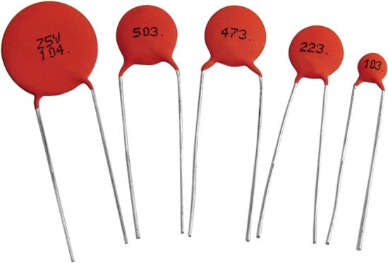
- Digital marking of capacitors (as well as numerical and alphabetic markings) is used in cases where the small area of the product does not allow a detailed record of the capacitance to be placed. Therefore, certain values are replaced with ordinary numbers and Latin letters, which are deciphered one by one to obtain complete information.

Everything is very simple - if only numbers are used (and on such products there are usually three of them), then you need to decipher them as follows:
- the first two digits indicate the first two digits of the capacity;
- the third digit indicates the number of zeros that must be added after the first two digits;
- such capacitors are always measured in picofarads.
Let's take for example the first option from the picture above with the entry 104. We leave the first two digits as 10. To them we add the number of zeros indicated by the third digit, that is, 4. We get a value of 100,000 picofarads. We return to the table at the beginning of the article, reduce the number of zeros and get an acceptable value of 100 microfarads.
If one or two digits are used, they remain that way. For example, the notations 5 and 15 represent 5 and 15 picofarads, respectively. Marking .55 is equal to 0.55 microfarads.
An interesting notation is made using letters either instead of a dot or as another quantity. For example, 8n2 means 8.2 nanofarads, while n82 means 0.82 nanofarads. For a certain class of capacitors, an additional code marking may be added at the end, for example, 100V.
- Labeling of ceramic capacitors using a numerical and alphabetic method is the standard for these products. Here, exactly the same encryption algorithms are used, and the inscriptions themselves are physically applied by the manufacturer to the ceramic surface.
- An outdated, but still used option is color indication. It was used in Soviet production to simplify the reading of markings even on very small products. The downside is that it is quite problematic to remember such a table right away, so it is advisable to have it on hand, at least at first. The colors are applied to the capacitors, where the marking is done in the form of monotonous stripes. Read as follows:
- the first two colors indicate the capacitance in picofarads;
- the third color shows the number of zeros that need to be added;
- the fourth and fifth colors respectively show the possible tolerance and nominal voltage supplied to the product.
- Marking of imported capacitors is carried out in similar ways, only the Latin alphabet can be used instead of Cyrillic. For example, on domestic versions there may be 5mk1, which means 5.1 microfarads. Whereas on imported ones this value will look like 5µ If the entry is completely incomprehensible, then you can contact the official manufacturer for clarification; most likely, the website has tables or a program that decipher its markings. However, this occurs only in exceptional cases and is rarely encountered.
Conclusion
The smaller the capacitor, the more compact recording it requires. However modern production is capable of applying fairly small values to the body, the decoding of which is carried out using the methods described above. Carefully check the obtained values to avoid damage to the assembled electrical circuit.
K73-17, K73-17V
Metallized polyethylene terephthalate film capacitors for a wide range of applications
Capacitors K73-17 are designed for operation in DC, AC and pulsating current circuits.
Produced in the USSR in different versions, differing different types conclusions, are still produced in Russia

K73-17, 0.033 µF at 400V
Made by SAHA - India
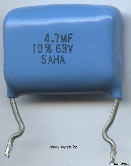
K73-17 4.7 µF ±10%, 63V
Manufacturer SAHA, India

K73-17, 1 µF ±10% 63V
Manufacturer - unknown

K73-17, 220nK P 630V, manufactured in July 1990

The same capacitor as above, with the same manufacturing date, but... appearance looks like some kind of hack...
Severo-Zadonsky capacitor plant ELECTROLIT, USSR

K73-17V 220nM 400V, manufactured in September 1989
Kuznetsk Capacitor Plant, USSR

K73-17 V 330nK 630V, manufactured in February 1990.
Kuznetsk Capacitor Plant, USSR
K78-2
Foil and metallized capacitors, polypropylene
Designed to operate in direct, alternating, pulsating currents and in pulsed modes
Filled with compound, rectangular, produced in the USSR, and are still produced in the Russian Federation
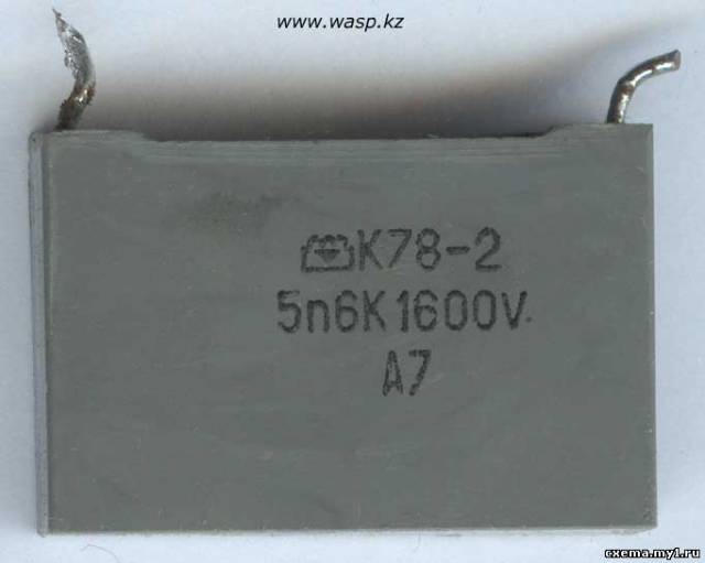
K78-2 5n6K 1600V A7

K79-2 10nJ 1000V A9
Novgorod capacitor plant, USSR

K78-2 1nJ 1600V A8
Novgorod capacitor plant, USSR

K78-2 5600pF ±5%, 1600V, manufactured in July 1990
Novgorod capacitor plant, USSR
K71-7
Metallized capacitors based on polystyrene film
Designed to operate in DC, AC, pulsating current circuits and in pulse modes.
Very high-quality precision capacitors were produced in this series.
Manufactured by the USSR, now manufactured by Russia. Body - rectangular, filled with compound

K71-7 4700 pF ±2%, 250V, manufactured in August 1990.
Severo-Zadonsky capacitor plant ELECTROLIT, USSR

K71-7 V, 4700 pF ±1%, 250 V, manufactured in September 1990.
Severo-Zadonsky capacitor plant ELECTROLIT, USSR

K71-7 0.05 µF ±0.5%, 250V, manufactured in October 1988.
Severo-Zadonsky capacitor plant ELECTROLIT, USSR
K73-15A
Polyethylene terephthalate foil sealed insulated capacitors
Designed to work in DC, AC and pulsating current circuits
![]()
Capacitor K73-15A 0.01 µF ±10%, 160V, manufactured in August 1988, manufacturer unknown
K73-21
Class “X” capacitors are designed to suppress industrial radio interference in the frequency range from 0.1 to 100 MHz in DC, AC and pulsating current circuits
By design - wrapped with adhesive tape, filled with epoxy compound at the ends
Manufactured in the USSR and now in Russia, often used in automotive electronics
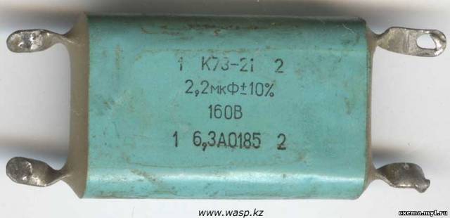
Dual capacitor K73-21, 2.2 µF ±10%, 160V, 6.3A
Manufactured in January 1985, manufacturer unknown

Dual capacitor K73-21, 3.3 µF ±10%, 50V, 6.3A
Manufactured in October 1984, manufacturer unknown
K53-19
Tantalum or niobium oxide semiconductor capacitors, polar, in an organic shell with unidirectional leads,
high stability with low leakage current and dissipation coefficient,
stable frequency and temperature characteristics and long service life

Capacitor K53-19 marked with colored stripes, 4.7 µF, 16 volts
Polar capacitor, conclusions different thicknesses, thick pin means + (plus)
MBGO-2
Designed to generate powerful discharge current pulses in the load and have high energy intensity
Capacitors are manufactured in rectangular metal cases, sealed by soldering, with spade leads
Produced in accordance with TU OZHO.462.124 TU acceptance “1”
According to the mounting method, capacitors differ in the presence or absence of special mounting plates on the housing

MBGO-2, 4 µF ±10%, 160V, manufactured in July 1988.
Nikond plant - Nikolaev, Ukrainian SSR
MBGCh-1
High-voltage pulsed metal-paper capacitors

MBGCh-1, 1 µF ±10%, 250V, manufactured in July 1988.
Ryazan plant Polikond, USSR
MBGP-2
Metal paper sealed rectangular capacitor

MBGP-2, 0.24 µF ±10%, 1600V, manufactured in September 1989. Batch No. 15
Manufacturer - Lakond, Novaya Ladoga, USSR (Amfi-Lakond)
OKBG-MP
Special (option) Paper Capacitor Sealed in a Metal Flat Case
Essentially the same KBG-MP...
It has been produced since time immemorial - the early 1960s, as it is now - unknown

OKBG-MP, 0.25 µF ±10%, 600V, manufactured in September 1984.
Severo-Zadonsky capacitor plant ELECTROLIT, USSR
K70-7
Polystyrene capacitors K70-7 are designed for use in DC, AC and pulsating current circuits
Made in the USSR, quite a rare and accurate capacitor

K70-7S, 66600 pF ±0.5%, 100V
Manufactured in December 1976 at the Vector plant, Ostrov, Pskov region
K40U-9
Sealed oil-paper capacitor
For operation in DC, AC, pulsed and pulsating current circuits
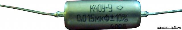
Capacitor K40U-9, 0.015 µF ±10%, 400V
K31-11-3
Mica capacitor is used in high-frequency circuits, filters, as shunt filters, etc.
The design of all mica capacitors is generally the same, K31-11-3 differ in the housing - a capsule made of epoxy compound

Capacitor K31-11-3, 0.01 µF ±5%, date 88 10 G
Manufacturer unknown

K31-11-3, 1200 pF ±5%, 88 12 G
Manufacturer unknown
K31-11-3, 360 pF ±5% G
Manufacturer unknown
K73-9
Polyethylene terephthalan foil capacitors
Designed to work in DC, AC, and pulsating current circuits
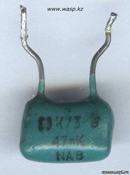
K73-9 47nK NA8, manufacturer - the logo is unclear...

K73-9 4N7 V, 100V, manufactured in November 1978
Microcomponent Plant, Karachaevsk, USSR
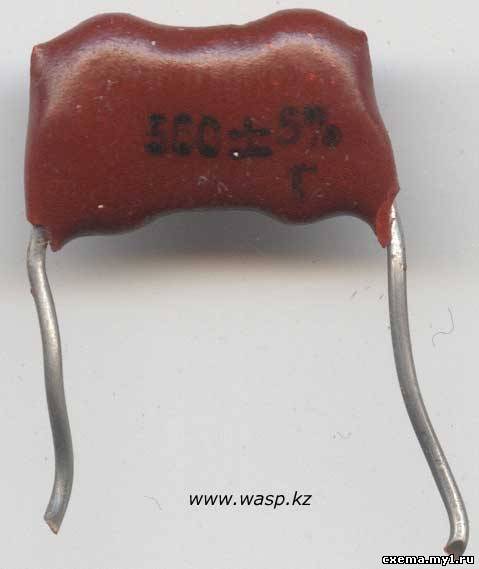
CSR
Pressed mica capacitors, non-polar. There are more than 10 types
The widest application. Produced in the USSR since the 1930s, they are no longer produced. Latest samples from the early 80s
The letter designation B, C and G means that a layer of silver is applied to the mica as a lining - those with G are the best

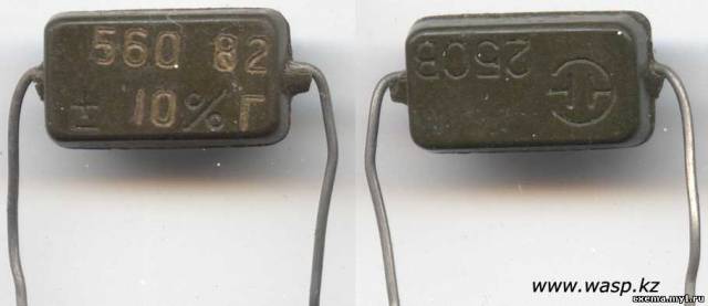
Capacitor KSO 560 pF ±5%, 250V, 1979, series G

KSO, N39I - 0.39 nF, or 390 pF. And - accuracy, +-04%, rated operating voltage 250 volts
Novosibirsk Capacitor Plant, USSR
Capacitor KSO 560 pF ±10%, 250V, series G, manufactured in 1982
Novosibirsk Capacitor Plant, USSR
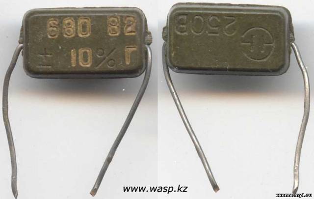
Capacitor KSO 680 pF ±10%, 250V, series G, manufactured in 1982
Novosibirsk Capacitor Plant, USSR

Capacitor KSO 100 pF ±10%, 250V, series G, manufactured in 1979
Novosibirsk Capacitor Plant, USSR
K15-5, KVDS
High Voltage Ceramic Capacitors

Capacitor K15-5 2n2 5kVH A5, manufacturer not specified


Capacitors KVDS 470 pF 1.6 kV N70 and 470 pF ±20% 3 kV N20 manufactured in May 1970.
Manufacturer unknown
KTP-3
Ceramic feed-through capacitors
Designed for operation in DC, AC and pulsed current circuits
Developed in the late 80s and still in production today

Capacitor KTP-3 15nZX A3
Manufacturer unknown
Mikhail Dmitrienko, Alma-Ata, 2012
 (1 ratings, on average: 5,00 out of 5)

