Signal processing. Television standards and formats
Both additional chrominance signals in PAL standard transmitted simultaneously in quadrature modulation (a variation), the typical subcarrier frequency is 4433618.75 Hz (4.43 MHz). In this case, the “red” color difference signal is repeated in the next line with a phase rotation of 180 degrees. To eliminate phase error, the PAL decoder adds the current line and the previous one from memory, thereby completely eliminating phase errors (typical of the NTSC system). When two signals are added, the “red” color-difference components cancel out, because their sign has changed. When subtracting two signals, the “blue” signals cancel each other out. Thus, the outputs of the adder-subtractor produce separated signals U and V, which are scaled R-Y and B-Y.
In analog television receivers, an ultrasonic delay line is used to remember the color difference signal from the previous line, in digital ones - RAM per line.
Thus, unlike NTSC, in the PAL standard, when using a standard analog decoder, the vertical color resolution is half that of a monochrome image (due to the summation of two adjacent lines across the field). This is quite acceptable, since the horizontal resolution in color is also lower due to the reduced bandwidth. Subjectively, due to the greater sensitivity of the eye to the brightness component, such deterioration is almost not noticeable in average pictures. It should be understood that in the transmitted signal the vertical color resolution is complete; resolution deterioration occurs only in analog PAL decoders.
The use of digital signal processing makes it possible to restore both the full vertical color resolution and improve the brightness/chrominance separation through the use of comb (or even more complex - the so-called 3D) subcarrier filtering.
The application of quadrature modulation is distinctive feature PAL is from the SECAM standard, the rotation of the phase of the “red” signal along the lines distinguishes it from NTSC, the YUV color model distinguishes it from all analog systems.
Geography of distribution
The PAL system is the main color television system in Europe (except France, Russia, Belarus), Asia, Australia and several countries in Africa and South America:
Heated discussions on the choice of color television systems in leading countries Western Europe ended in favor of the PAL system - behind it was fifteen years of experience in broadcasting and production of equipment and televisions in the USA, Japan, Canada and other countries using the NTSC system. Of course, there was also politics involved (this system was jokingly called the “NATO system”) - when, somewhat later, Italy was preparing to choose a color television system, the then ruling President of France, J. Pompidou, specially came to Rome and spoke in parliament with an appeal "show Roman solidarity and accept French system" However, Italy did not show such solidarity and leaned towards the PAL system.
see also
- PALplus
| Television broadcast standards | |
|---|---|
| Analog | |
| SECAM PAL NTSC | |
| Multichannel audio | BTSC (MTS) NICAM Zweiton (A2, IGR) |
| Additional signals | Teletext Subtitles CGMS-A GCR PDC VBI VEIL VITC WSS XDS |
| Digital | |
| HDTV DVB ATSC ISDB SBTVD | |
| Multichannel audio | AAC (5.1) MP2 (Musicam) PCM LPCM |
| Hidden signals | Teletext Subtitles CPCM AFD EPG |
| Broadcast video formats | |||||||||||
|---|---|---|---|---|---|---|---|---|---|---|---|
| Analog |
| ||||||||||
The NTSC color television system was developed in the USA in 1950–1953. National Committee Television Systems(National Television System Committee) and approved in the country as national standard. Later, the NTSC system was adopted as a standard in Canada, in most countries of the American continent, in Japan, Korea, Taiwan and some other countries.
The NTSC system transmits luminance and two color difference signals as signals. Transmission of color difference signals is carried out in the luminance spectrum at one color subcarrier frequency f S(Figure 5.8).
Rice. 5.8. NTSC Image Signal Spectrum
The subcarrier voltage modulated by color difference signals is called color signal . Sum of luminance and chrominance signals U S forms full color signal U P. In order to modulate one subcarrier frequency with two color-difference signals, a quadrature amplitude modulation method. Its essence lies in the summation of two subcarrier frequency voltages modulated by each of the color difference signals in separate amplitude modulators (Figure 5.9). The subcarrier frequency is supplied to the modulators in quadrature, i.e. with a phase shift of 90°. The color signal obtained as a result of addition is modulated not only in amplitude, but also in phase.
Rice. 5.9. Simplified block diagram of the encoding device
Indeed, the amplitude of the chrominance signal is:
![]() (5.1)
(5.1)
and the phase shift φ of the vector U S relative to one of the vibrations
 , (5.2)
where in turn are determined by modulating color-difference signals.
The NTSC system does not use conventional amplitude modulators, but balanced , which, suppressing the subcarrier itself, leave only the side components of the spectrum. Balanced modulation has certain advantages over conventional amplitude modulation (Figure 5.10). With the same range of modulating signals compared to conventional modulation, balanced modulation generates a color signal that is at least twice as amplitude, which reduces its visibility on the screen of a black-and-white TV, for which the color signal should be considered as interference. Thus, the compatibility of black-and-white and color television systems is improved. In turn, the quality of compatibility is further enhanced when rendering uncolored or lightly colored image details. In these cases, the color-difference (modulating) signals are zero or small in amplitude, and at the output of the balanced modulators the signal also tends to zero.
A) 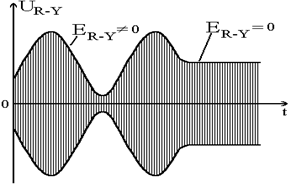
b) 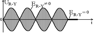
Rice. 5.10. a) amplitude modulation
b) balanced modulation
In an NTSC color receiver from the received color signal U S its quadrature components must be isolated to obtain the original color difference signals. Since the separation of signals can be represented as the operation of projecting the vector U S onto two orthogonal axes coinciding with the modulation axes.
The problem in this representation can be solved using synchronous detector. In synchronous detection, two signals supplied to the detector input are multiplied. If one of these signals is a color signal received by the television receiver U S, and the other – the so-called reference voltage U op representing the subcarrier frequency oscillation f S with the initial phase φ=0, then the voltage at the detector output U out will be equal to:
Where U op is the amplitude of the above reference voltage.
Using the known trigonometric relation
we get
Assuming the amplitude of the reference voltage to be constant and installing a low-pass filter at the output of the synchronous detector, excluding the second term on the right side of the equation, we will make sure that the problem of isolating one of the quadrature components has been solved:
![]() ,
,
where k is the proportionality coefficient.
If voltage is applied to the synchronous detector as a reference voltage, then
![]() ,
,
those. the second quadrature component will be highlighted.
Thus, the device for separating quadrature components must consist of two synchronous detectors and a reference subcarrier frequency generator, synchronized in frequency and phase with the transmitting generator. However, such information is not contained in the received TV signal, since with balanced modulation the subcarrier itself is suppressed, and the side frequencies are a modulation product depending on the transmitted color (and therefore with phase shifts different from the unmodulated value f S).
To make the reference subcarrier generator f S in the receiver could work with the phase specified at the television center, it is synchronized with a special signal called color burst signal . It is transmitted in the interval reverse horizontal scanning at the horizontal blanking pulse (HCP) site behind the horizontal synchronizing pulse (HSP) and is a packet of color subcarrier oscillations of 8...10 periods (Figure 5.11). This package is also called color flash. The flash oscillation frequency is f S, the phase is 180° (the oscillation vector of the package coincides with the negative direction of the axis B–Y). The packet is transmitted in all scan lines, except for an interval of 9H duration (H is the duration of one line), in which equalizing pulses and vertical sync pulses are transmitted (on the vertical blanking pulse). The intervals between flashes are equal to H.
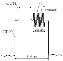
Rice. 5.11. Signal flash
Thus, with quadrature modulation, the amplitude of the resulting color signal characterizes the color saturation, and the phase characterizes the color tone. Color vectors can be visually represented graphically on a color diagram in polar system coordinates (Figure 5.12)
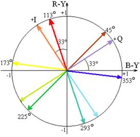
Rice. 5.12. Color diagram in polar coordinate system
When selecting the color subcarrier frequency f S The following conditions must be met.
1. To reduce the visibility of interference from the color signal in the image on a black-and-white TV U S color subcarrier frequency f S should be as high as possible, since in this case the structure of the pattern from the interference will be smaller and, therefore, less noticeable. On the other hand, the meaning f S must be significantly less than the maximum frequency f max in the spectrum of the brightness signal, so that the requirement for professional compatibility of systems is met, i.e. so that the full color signal fits within the standard color signal band. Difference (f max –f S) determines the maximum width of the sideband of the color signal, and therefore the maximum possible width of the spectrum of color difference signals. As practice has shown, this value cannot be less than 0.6 MHz, since otherwise noticeable color borders will appear on the color image in the receiver at the vertical boundaries between different colors. Since in American standard f max=4.18 MHz, then f S must be at least 3.58 MHz.
2. For the same purpose of reducing the visibility of the pattern on the screen of a black-and-white TV obtained from the influence of a subcarrier on it, its frequency f S is strictly linked to the image scanning frequency. In this case, this relationship is subject to the relationship:
![]() , (5.4)
, (5.4)
where n is an integer and is the frequency of lines. Then the interval of one, for example the first, line fits an integer number of periods of the color subcarrier and another half of the period. Therefore, in the next odd line the phase of the signal will change to the opposite, and so on from line to line. As a result of luminance modulation under the influence of the color subcarrier, a grid of dark and light strokes, arranged in a checkerboard pattern, will appear on the TV screen.
Since a frame contains an odd number of lines, the signal polarity in the corresponding lines will be reversed when the next frame is transmitted. The eye, due to the inertia of the visual apparatus, will average this picture. Thus, due to compensation from line to line and from frame to frame, the color subcarrier signal on the TV screen will be barely noticeable, and the smaller the grid structure, the less noticeable.
Since the spectrum of the brightness signal is discrete and periodic, the harmonics of the chrominance signal, which is also discrete and periodic, can be placed in the gaps between its harmonics. When condition (5.4) is satisfied, the spectral components of the color signal are located exactly in the middle. The so-called alternation (interweaving) of frequency spectra of brightness and color signals (Figure 5.13), which in principle makes it possible to separate these two signals in the receiving device with great accuracy.
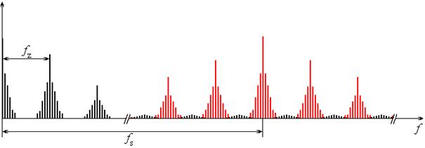
Rice. 5.13.Frequency spectrum of brightness and color signals
3. Noise in the image due to the presence of a subcarrier frequency in the spectrum of the full TV signal can also arise due to beats between the subcarrier frequency of the color signal and the second intermediate frequency of the audio. To reduce the noticeability of interference, its frequency is equal to the difference in subcarrier frequencies f S and the second intermediate frequency of sound, for the same reasons that were stated in the previous paragraph, is also made equal to the odd harmonic of the half-line frequency:
![]() , (5.5)
, (5.5)
Where k– an integer. From (5.3) and (5.4) it follows that
 .
.
Replacing f S its value from (5.4), we obtain:
 . (5.6)
Thus, requirement (1.5) necessarily entails requirement (1.6). But in any television broadcasting system it is determined by the separation of the image and sound carrier frequencies, and (1.6) can be written as
 , (5.7)
where m is an integer.
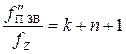
In the US standard for black and white television, unlike any of the European standards, this condition was not met. In the USA in black and white television = 4.5 MHz; =15750 Hz. Thus, their ratio was 285.714. To satisfy condition (5.7), this ratio had to be rounded to the nearest integer, i.e. to 286, which forced the developers of the NTSC system to change the scan frequencies by 0.1% accordingly: =15734.27 Hz, =59.94 Hz (instead of 60 Hz). Such an insignificant but fundamental change in the scan frequencies in the color system did not require alteration of the scan generators of black-and-white TVs, since the indicated new values of the scan frequencies are obviously within the capture band of the TV scan generators synchronized by them.
4. Multiplier (2n+1) in (5.4) should consist of factors that are as small as possible in order to facilitate the achievement of stable frequency division when obtaining the line frequency in the clock generator from the frequency of the master oscillator that generates the frequency f S. The optimal number turned out to be (2n+1)=455 (13x7x5), which determined the choice of subcarrier frequency ![]() MHz. The standard provides for an acceptable instability of this value of no more than 0.0003%, i.e. no worse than 10 Hz.
MHz. The standard provides for an acceptable instability of this value of no more than 0.0003%, i.e. no worse than 10 Hz.
Color difference signals E I and E Q
In the NTSC system in its final version, not signals were used as color signals, but their derivatives - signals and. The expediency of switching to these signals is explained by the fact that for small items our vision is dichromatic (two-color). Dichromatism in normal vision occurs for objects that, when observed, have a size of 12–20 arc minutes. When observing objects of this size, the human visual system does not distinguish the difference between blue and green, red and purple colors. All color shades are perceived as a mixture of orange and blue flowers. As details decrease further, the eye ceases to distinguish color, and we see small parts like black and white. If you superimpose on the blurred boundary of the transition from one color to another sharp drop brightness, the eye will see a clear transition from one color to another.
With regard to television, the following conclusions follow from this. Television image details ranging from 10 to 22 arcminutes can be transmitted within a limited color scheme, a corresponding mixture of orange and blue colors. The exclusion of small color details from the transfer should not noticeably affect the sharpness of color transitions if the brightness transitions are reproduced sharply by the TV system.
Experiments have shown that all three signals must be transmitted by the TV system in a frequency band of up to 0.5 MHz. In the frequency band from 0.5 MHz to 1.5 MHz, it is necessary to transmit color signals corresponding to a mixture of orange and blue. In the frequency band from 1.5 MHz to the maximum frequency of the spectrum, one colorless luminance signal can be transmitted.
The use of new quadrature components makes it possible to transmit a color image in the following way. The brightness signal is transmitted over the full frequency band. The color signal is transmitted in a frequency band up to 1.5 MHz, and the signal in a band up to 0.5 MHz. In the frequency range from 0.5 to 1.5 MHz, only two signals are transmitted, providing the reproduction of orange-red and blue-green colors. The transition from signals to signals allows one to somewhat improve the parameters of the system, since the interference from color signals in the luminance channel is reduced and it becomes possible to slightly increase the subcarrier frequency.
Application of signals E I And E Q, occupying a smaller frequency band in the spectrum of the luminance signal, instead of conventional color-difference signals turned out to be appropriate, since the video channel width in the US standard is only 4.2 MHz and the placement color information in the spectrum of a brightness signal presents certain difficulties. In the European NTSC version used for comparison various systems color television with a video channel width of 6 MHz, signals were used.
Figure 5.14 shows a simplified block diagram of an encoder in the NTSC system. The original signals are signals. The dashes in the signal designations indicate that the signals have been previously gamma-corrected. At the output of the matrixing circuit M a brightness signal and color difference signals are generated. The synchronization signal of the SSP receiver is introduced into the brightness signal. Low pass filters LPF1 And LPF2 The signal frequency bands are limited to 1.3 and 0.6 MHz, respectively. The subcarrier frequency generator produces a sinusoidal signal with a frequency of 3.579545 MHz and a phase of 180°, corresponding to the negative axis direction B–Y. To a balanced modulator BM signal subcarrier frequency comes from the oscillator with a delay of 57°, which is created by the phase shifter FV1. To a balanced modulator BM signal, the subcarrier frequency oscillation arrives with an additional 90° delay obtained in FV2, thereby providing the conditions for quadrature modulation of one subcarrier with signals. Quadrature components from the outputs of balanced modulators U I And U Q fed to the adder, which produces a color signal U S. In the adder the color signal U S added to the luminance signal. At the output of this adder, the total frequency band is determined by the low-pass filter in the range from 0 to 4.18 MHz. As a result of this limitation, the quadrature component U Q – LZ1 by approximately 0.7 μs, and in the channel - LZ2 by 0.5 µs. The error in the time alignment of all three signals should be no more than half the scanning duration of the black-and-white image element (0.05 μs). Otherwise, in a color image, there may be a noticeable misalignment of the colored areas and the parts to which these areas belong.
Color Burst U The CV is formed in the valve device K using strobe pulses, the temporary position of which corresponds to the position of the color flash on the rear platform of the horizontal blanking pulse (see Figure 5.11). In the adder, the color synchronization signal is added to the brightness and chrominance signals.
To satisfy condition (5.1), horizontal synchronizing pulses are obtained by repeatedly dividing the subcarrier frequency f S in frequency divider DC.
Rice. 5.14. Block diagram of an NTSC system encoder
Block diagram of a decoding device
Composite signal U P, containing the brightness and chrominance signals, as well as color flashes and the receiver synchronization signal, is fed to a brightness signal amplifier and a bandpass filter PF color signal (Figure 5.15). In the luminance channel using notch filter RF, tuned to the subcarrier frequency, the chrominance signal is suppressed, eliminating interference from it in the form of the chess piece pattern discussed above. A bandpass filter in the color-difference channel extracts from the full signal U P chrominance signal and color burst signal. At the same time, attention is also paid to the maximum suppression of the second intermediate audio frequency (4.5 MHz) in the signal, which can cause unwanted beats with the color subcarrier. Chroma signal U LZ1 And LZ2.
The color burst signal is separated from the chrominance signal by a valve device K, which transmits color flashes to its output when strobe pulses generated in the device arrive FSI. In turn, the forming device is controlled by horizontal synchronizing pulses, separated from the complete signal in the synchronizing pulse selector.
Color flashes are designed to synchronize the color subcarrier generator f S, which has quartz stabilization to ensure accuracy.
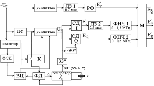
Rice. 5.15. Block diagram of an NTSC system decoder
Synchronization is parametric, the control voltage is generated by the phase detector FD, which compares the frequency and phase of oscillations from the generator and color flashes. Phase-locked loop circuitry is most simply carried out to a value of 90° with respect to the flash phase, i.e. to the axis R-Y. Thus, to ensure detection on the axis I(in a synchronous detector SDI), it is necessary to create oscillations of the self-oscillator in the phase shifter FV1 advance by 33°. Additional delay in FV2 at 90° will provide detection in SDQ per axis Q.
The color signal amplifier uses gate pulses to suppress the oscillations of color flashes to eliminate their envelope at the output of synchronous detectors. Otherwise, at the edge of the image, this envelope may create a colored vertical stripe corresponding to the position of the flash on the horizontal blanking area.
The color signal channel must also be blocked when a black-and-white image is being received, since otherwise color coarse-grained moire would appear on the screen of a color kinescope. The latter are the product of beats in synchronous detectors of high-frequency components of the brightness signal with oscillations of an autonomously operating subcarrier generator. Chroma switch VC receives control voltage to block the channel from the phase detector. When broadcasting a color program, i.e. in the presence of color flashes, from the phase detector to VC a constant voltage of one sign is received, but during black-and-white broadcasting this voltage changes its sign.
If we exclude the phase shifter from the considered block diagram FV1 at 33°, then synchronous detection will be carried out on the axis R-Y And B–Y, and therefore, signals will be received at the outputs of the detectors. But in this case, due to the diversity of the components U I And U Q Crosstalk between signals may occur.
To prevent these distortions, both low-pass filters at the output of the detectors must be narrow-band: 0...0.6 MHz, which will noticeably worsen color clarity. Therefore, this version of the decoding device is less common.
From the point of view of the applied method of modulating the color subcarrier with video color signals, the NTSC system has the following main features:
Good use transmission channel (large volume of transmitted information with high noise immunity);
High quality color image in the absence of unacceptable distortions in the transmitting path (in particular, high color clarity horizontally and vertically);
The absence of moire and brightness flickering in the image on the screens of color and black-and-white television receivers when the object of transmission moves;
Good compatibility(low visibility of interference from the color signal);
The correctness and simplicity of the color signal shape when transmitting the test signal of color stripes, which makes it easier to control the operation of the equipment and configure it;
High noise immunity of color video signals in the receiver from fluctuation noise. At the same time, the visibility of noise in a color image increases smoothly as the signal-to-noise ratio decreases, and the noise in the image has a structure close to that on black-and-white television, although coarse-textured noise is somewhat more noticeable due to noise from the color signal channel;
High noise immunity of the color synchronization circuit from fluctuation noise;
Easily mix complete video signals U P =+ U DV from various cameras, no different from mixing signals in black and white television.
The NTSC system has the following disadvantages, due to which it was not adopted as a standard in Europe for 625-line scanning:
The requirements for the absence of distortion of the amplitude and phase of the color signal at the subcarrier frequency and for the undistorted transmission of the required frequency band are very stringent, and their implementation during the creation and operation of equipment, as well as communication channels, is associated with significant difficulties;
With multi-beam reception (for example, in mountainous conditions) and in the presence of reflected signals, distortions in the amplitude and phase of the color signal occur, reducing the quality of the color image;
When recording a complete signal U When transferring to magnetic tape and playing it, it is necessary to ensure strict constancy of the speed of movement of the magnetic tape relative to the magnetic heads, which is especially important for repeated rewriting. To fulfill this requirement, the VCR must have high-quality mechanisms and special units for electrical correction of the inconstancy of the speeds of the mechanisms.
PAL (Phase Alternating Line) is a television signal standard developed by Telefunken engineer Walter Bruch in Germany in 1963.
Like all analog television standards, PAL is adapted and compatible with older monochrome (black and white) television broadcasting. In adapted analogue color television standards, an additional color signal is transmitted at the end of the monochrome television signal spectrum.
It is known that any color perceived by human vision can be composed of primary colors: red (R), green (G) and blue (B). This color model is abbreviated RGB. Due to the predominance of the green color component in the average television picture and to avoid redundant coding, additional color signals are used R-Y differences and B-Y (where Y is the overall brightness of the monochrome TV signal). The PAL system uses the YUV color model.
Both additional color signals in the PAL standard are transmitted simultaneously in quadrature modulation (a type of amplitude modulation - it is the sum of two carrier oscillations of the same frequency, but shifted in phase relative to each other by 90 degrees, each of which is modulated in amplitude by its own modulating signal), typical frequency subcarrier - 4433618.75 Hz (4.43 MHz). In this case, the “red” color difference signal is repeated in the next line with a phase rotation of 180 degrees. To eliminate phase error, the PAL decoder adds the current line and the previous one from memory, thereby completely eliminating phase errors (typical of the NTSC system). When two signals are added, the “red” color-difference components cancel out, because their sign has changed. When subtracting two signals, the “blue” signals cancel each other out. Thus, the outputs of the adder-subtractor produce separated signals U and V, which are scaled R-Y and B-Y.
In analog television receivers, an ultrasonic delay line is used to store the color difference signal from the previous line; in digital receivers, RAM per line is used.
Thus, unlike NTSC, in the PAL standard, when using a standard analog decoder, the vertical color resolution is slightly lower than the resolution of a monochrome image (due to the summation of two adjacent lines across the field). This is quite acceptable, since the horizontal resolution in color is also lower due to the reduced bandwidth. Subjectively, due to the greater sensitivity of the eye to the brightness component, such deterioration is almost not noticeable in average pictures. It should be understood that in the transmitted signal the vertical color resolution is complete; resolution deterioration occurs only in analog PAL decoders.
The use of digital signal processing makes it possible to restore both the full vertical color resolution and improve the brightness/chrominance separation through the use of comb (or even more complex - the so-called 3D) subcarrier filtering.
The use of quadrature modulation is a distinctive feature of PAL from the SECAM standard, the rotation of the phase of the “red” signal along the lines distinguishes it from, the YUV color model distinguishes it from all analog systems.
A television frame of the PAL standard consists of 576 lines (the total number is 625, some of which are service lines), each line consists of 720 fragments, i.e. is a 720*576 matrix.
Each frame consists of “fields” - alternating even and odd lines; alternating even and odd fields allows you to reduce the flickering of the picture.
Several modifications of the PAL standard are used, with differences in broadcast bands, video bandwidth and audio carrier frequency.
| Standard | Broadcast range | Lines/Fields | Total bandwidth, MHz | Video signal bandwidth, MHz | Carrier frequency of sound, MHz | Visible lines |
|---|---|---|---|---|---|---|
| PAL B | VHF | 625/50 | 7 | 5,0 | 5,5 | 576 |
| PAL G,H | UHF | 625/50 | 8 | 5,0 | 5,5 | 576 |
| PAL I | UHF/VHF | 625/50 | 8 | 5,5 | 6,0 | 582 |
| PAL M | UHF/VHF | 525/60 | 6 | 4,2 | 4,5 | 480 |
| PAL D | VHF | 625/50 | 8 | 6,0 | 6,5 | 576 |
| PAL N | UHF/VHF | 625/50 | 6 | 5,0 | 5,5 | 576 |
| PAL Nc | UHF/VHF | 625/50 | 6 | 4,2 | 4,5 | 576 |
Most analog cameras for CCTV systems operate in the PAL D standard.
PAL I television signal frequency spectrum:
Principle of amplitude and frequency modulation:
![]()
Signal - carrier frequency.
AM—amplitude modulated signal.
FM is a frequency modulated signal.
PAL color television system
The PAL system was developed by the German company Telefunken and adopted as a standard in most Western European countries (Germany, Great Britain, Sweden, Austria, Norway, Belgium, Denmark, Spain, Italy, etc.). Currently, the PAL system is the most widespread color television system in the world. It is used, in addition to European countries, in most countries of Africa, Asia, Australia, and in some countries South America. The name of the system is an abbreviation of the initial letters English phrase"Phase Alternation Line" (phase alternation along lines).
The PAL system, created as an alternative to the NTSC system, however, can be considered as its successful modernization. It uses the same signals as other color television systems, and transmits these signals in the same way as in NTSC, by quadrature balanced amplitude modulation of a subcarrier frequency located in the spectrum of the luminance signal. The difference from the NTSC system is that the phase of one of the quadrature components of the chrominance signal varies from line to line by 180°. This made it possible to eliminate the main disadvantage of the NTSC system - sensitivity to differential phase distortion, and also obtain a number of other important advantages.
Figure 5.23 shows how a color signal is generated in the PAL system. Just like in the NTSC system, it is formed from two quadrature components. But one of these components, with the beginning of each next line, changes phase by 180°. The resulting chrominance signal vectors in adjacent rows are complex conjugate. In order to correctly decode such a sequence of signals at the receiving device, it is necessary in the synchronous signal detector to switch the phase of the reference subcarrier frequency oscillator by 180° at the same frequency as at the transmitting end. Phase switching is equivalent to the reverse transformation of vectors into their original complex conjugate vectors, respectively. The operating conditions of a synchronous signal detector do not differ from its operation in the NTSC system.
Rice. 5.23. Subcarrier phase switching during signal transmission
color in PAL system
Let us consider how such a phase switching procedure affects the differential phase distortions that arise in the transmission path. In Figure 5.24 on the color chart in the axes R– Y/ B–Y Some characteristic colors and a vector corresponding to the rendering of the purple color are marked. According to the principle of signal transmission in the PAL system, (n+1) The th line will receive the vector complex conjugate of the vector . If differential phase distortions occur in the path, then, regardless of their causes, the vectors and will change their position relative to the original ones by the same value Δφ (Figure 5.24, b). In the figure, the phase error has shifted both vectors counterclockwise. In the receiving device, phase switching of the reference subcarrier oscillator in the channel R-Y will turn a vector into its conjugate vector (Figure 5.24, V). To analyze the distortions that arise during the transmission process, combine the vectors and on one graph (Figure 5.24, G). It shows that the neighboring n-th and (n+1) The th lines are distorted in different ways. Color n-th line shifted towards red, and the color (n+1)-th line – towards the blue color. The undistorted color corresponds to the average between the vectors and the position. Thus, averaging these two vector quantities would make it possible to compensate for phase distortions that arise during the transmission process. Most in a simple way averaging is the averaging of sensations by the visual apparatus itself. Due to their proximity to each other n-oh and (n+1)-th line the mechanism of spatial addition of colors works. The different color shades of two adjacent lines due to distortion add up, causing the feeling of an average color between them, thus compensating for the distortion:
a) color chart;
b) phase error during signal transmission;
c) signals in the receiver after switching the phase of the reference oscillation;
d) combining the signals of two adjacent lines.
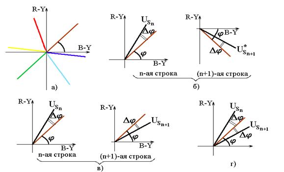
Rice. 5.24. Compensation for differential phase distortion
in PAL system
The considered method of visual compensation for distortion is implemented in the so-called “simple” PAL receiver (Simple PAL or PAL S). The image turns out to be quite satisfactory if the phase errors Δφ do not exceed 25° (in NTSC - no more than 5°). At large values the error of the integrating action of the eye is no longer enough; a noticeable difference in the color of adjacent lines of the field appears, especially in yellow, blue and blue colors("blinds" effect). The nonlinearity of the modulation characteristics of the kinescope aggravates this effect. Therefore, the method of visual compensation for phase distortions in the PAL system has not found widespread use.
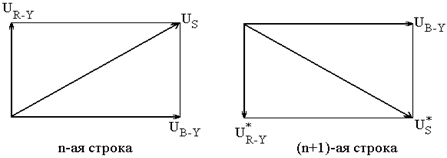
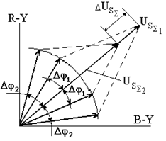
The best results can be obtained by the electrical addition of the chromaticity vectors and two adjacent field lines (Figure 5.25). The geometric half-sum of these vectors corresponds to the position of the undistorted color in the diagram. Only color tone distortions are compensated, since the length of the resulting vector depends on the magnitude of the phase error Δφ. As the error increases (Δφ 2 > Δφ 1), the length of the total vector decreases (<). Это уменьшение пропорционально cosΔφ. Since the length of the vector determines the saturation of the transmitted color, it can be concluded that in the PAL system, color tone distortions due to phase errors are transformed into saturation changes, which are less noticeable. So, if the threshold of visibility in color tone corresponds to the angular shift on the color diagram φ=5...10°, then the threshold in saturation is approximately 20%, which corresponds to the angle Δφ=37°.
The phase error compensation mechanism in the PAL system eliminates not only differential phase distortion. The impact on image quality of the accuracy of subcarrier reconstruction by the reference oscillator in the receiver is also reduced. The error Δφ in the oscillation phase of the reference oscillator is equivalent to rotating the axes of the color graph relative to the transmitted chromaticity vectors and by the same angle Δφ. And this, as has been shown, is compensated by averaging these vectors.
The averaging method based on summation assumes the simultaneous presence of signals from two sequentially transmitted lines. Therefore, the PAL receiver must include a signal delay unit for the duration of one line. If a signal is currently received at its input (n+1)-th line, then at the same time the signal of the previous one is present at its output n-th line. By feeding these signals to the adder, the desired distortion compensation can be obtained. However, a PAL decoder often uses a slightly different circuit (Figure 5.26), containing two adders. This scheme allows not only to average the signals of two lines, but also to separate the two quadrature components of the color signal. This separation is more efficient than separation in synchronous detectors (as was done in the NTSC system), and therefore crosstalk is less likely to occur between signals.
Rice. 5.25.Compensation for color distortions by adding signals from adjacent lines
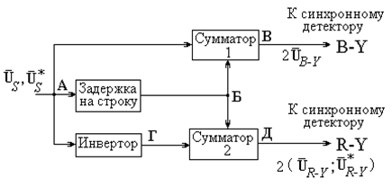
Rice. 5.26. Signal delay block in the PAL system
Block diagram of the encoding device
The PAL system transmits a luminance signal and two color difference signals U And V. Signals U And V equal to color difference signals reduced by compression factors:
 (5.12)
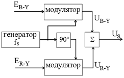
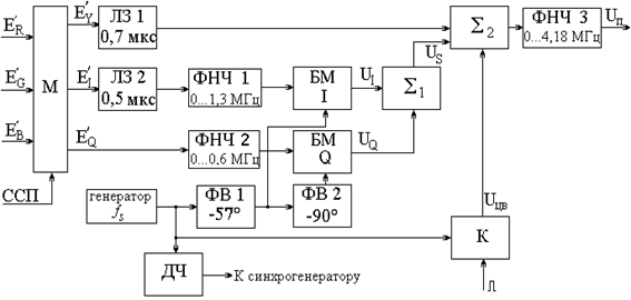
Signal generation, U And V produced in a matrixing device (Figure 5.27). Video frequency bands U And V are limited LPF up to 1.3 MHz at –2 dB. In adders 1 And 2 color difference signals are mixed with pulses that form a color flash and are sent to balanced modulators , which work in quadrature, i.e. the shift between subcarrier frequency oscillations in both modulators is 90°. This shift is provided phase shifter 90°, included in the circuit of the balanced component modulator U V. The phase change of this component through the line is carried out by a switch connecting the modulator, or directly with 90° phase shifter, or with additional inverter at 180°. Switching is provided using a switching pulse generator synchronized with the line frequency.
Quadrature components U U and U V, folding into adder 3, form a chrominance signal U S, which, together with the luminance and sync signals of the receiver, represents a complete color (composite) signal U V. Delay line in the luminance signal path has the same purpose as in NTSC and SECAM systems.
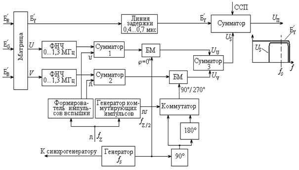
Rice. 5.27. Block diagram of a PAL system encoder
The subcarrier frequency generator is a highly stable device with quartz frequency stabilization, the value of which f S=4.43361875 MHz. Just like in the NTSC system, a rigid connection is provided between the subcarrier frequency and the scanning frequencies. However, the choice of the subcarrier value itself in the PAL system has its own characteristics.
First of all, they are related to signal switching U V (each line 180°). This switching makes it impossible to select a subcarrier equal to the odd harmonic of the half-line frequency. In this case, the odd parity of the half-cycles of the subcarrier oscillation in the line interval plus phase switching by 180° would result in a phase match of the signal U V in all lines of the image. And this would lead to an increase in the visibility of the subcarrier in the image in the form of a vertical line structure. In turn, it is impossible to select a subcarrier value that is a multiple of the horizontal frequency, since the component U U, transmitted without phase switching, creates the same interference.
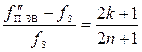
The system developers made a compromise solution. The subcarrier frequency was chosen equal to the sum of the odd harmonic of the quarter-line frequency f Z and frame rates:
![]() . (5.13)
. (5.13)
This dependence can be approximately expressed as
 ,
,
which determines the placement in a line interval of 284 subcarrier periods minus one quarter. Thus, in the PAL system, unlike the NTSC system, they implement not a half-line shift, but a so-called quarter-line shift of the harmonics of the color signal relative to the harmonics of the horizontal frequency. Frame rate components f frame cause an additional change in the polarity of the subcarrier in each field by 180°. Experiments have shown that this choice of subcarrier ensured high compatibility of the PAL system.
The structure of the color signal spectrum in the PAL system differs from the signal spectrum in the NTSC system in that the chromaticity harmonics are closer to the luminance signal harmonics (the interval between them is ¼ f Z). This complicates somewhat, but does not exclude the possibility of comb filtering when separating these signals at the receiver.
In the most common European standard of the PAL system, the full color signal is limited in bandwidth within the range of 0 ... 5 MHz. At the specified value of the subcarrier frequency, the highest lateral oscillations of the chrominance signal for both quadrature components U U and U V are asymmetrically suppressed. In an NTSC system, such a limitation of the two quadrature signals would lead to crosstalk distortion between them in the receiving device. In the PAL system, the principle of progressive signal switching makes these distortions minimal, with virtually no effect on image quality.
Video standards
Since we are talking about video formats has already been raised and quite a lot has already been said about it, including about analog And digital video recording formats, so I decided to talk directly about such common video standards How: NTSC, PAL And SECAM. Let's figure out how they differ from each other.
If you decide to purchase a camera abroad, especially in the US and Japan, be extremely careful. Prices in these countries are extremely attractive, only all video equipment is designed to work in NTSC(however, especially for Russian tourists there are stores selling electronics in the system PAL, but here you need to be doubly vigilant).
In this regard, it makes sense to delve deeper into the concept of such abbreviations as NTSC, PAL, SECAM.
What does "NTSC" mean?
NTSC- this is abbreviated. English National Television Standards Committee - National Television Standards Committee - standard analog color television, developed in the USA. On December 18, 1953, color television broadcasting was launched for the first time in the world using this particular systems. NTSC adopted as a color television standard ( video) also in Canada, Japan and several countries of the American continent.
Technical features NTSC:
- number of fields - 60 Hz (more precisely 59.94005994 Hz);
- number of lines (resolution) - 525;
- subcarrier frequency - 3579545.5 Hz.
- number of frames per second - 30.
- Beam scanning is interlaced (interlacing).
What does "PAL" mean?
PAL- this is abbreviated. from English phase-alternating line - standard analog color television, developed by the engineer of the German company “Telefunken” Walter Bruch and presented as standard television ( video) broadcast in 1967.
Like all analog television ( video) standards, PAL is adapted and compatible with older monochrome (black and white) television broadcasting. In adapted analog standards In color television, an additional color signal is transmitted at the end of the monochrome television signal spectrum.
As is known from the nature of human vision, the sensation of color consists of three components: red (R), green (G) and blue (B). This color model is denoted by the abbreviation RGB. Due to the predominance of the green color component in the average television picture and to avoid redundant coding, the difference between R-Y and B-Y is used as an additional color signal (Y is the overall brightness of a monochrome television signal). In system PAL use a color model YUV.
Both additional chrominance signals in PAL standard transmitted simultaneously in quadrature modulation (a variation of AM), the typical frequency of the subcarrier signal is 4433618.75 Hz (4.43 MHz).
In this case, each color difference signal is repeated in the next line with a phase rotation with a frequency of 15.625 kHz by 180 degrees, due to which the decoder PAL completely eliminates phase errors (typical of the system NTSC). To eliminate the phase error, the decoder adds the current line and the previous one from memory (analogue television receivers use a delay line). Thus, objectively, color television images in video standard PAL has half the vertical resolution of a monochrome image.
Subjectively, due to the greater sensitivity of the eye to the brightness component, such deterioration is almost not noticeable in average pictures. The use of digital signal processing further mitigates this disadvantage.
What does "SECAM" mean?
SECAM- this is abbreviated. from fr. Séquentiel couleur avec mémoire, later Séquentiel couleur à mémoire - sequential color with memory - standard analogue color television, first used in France. Historically, it is the first European color television standard.
Color signal as standard SECAM transmitted in frequency modulation (FM), one color component in one television line, alternately. The previous R-Y or B-Y signal is used as the missing lines, respectively, receiving it from memory (in analog television receivers a delay line is used for this). Thus, objectively, color television images in the standard SECAM has half the vertical resolution of a monochrome image. Subjectively, due to the greater sensitivity of the eye to the brightness component, such deterioration is almost not noticeable in average pictures. The use of digital signal processing further mitigates this disadvantage.
It is customary to decipher the abbreviation as a joke SECAM as “System Essentially Contrary to AMerican” (a system essentially opposite to the American one).
By the way, videotapes marked NTSC The quality and duration of recordings do not meet the standard PAL.
 (1 ratings, on average: 5,00 out of 5)

