Dimensions of the ground loop according to the standards. Installation of an external ground loop
What is a ground loop? Protective grounding necessary for electrical connection non-current-carrying parts of electrical equipment with soil.
Why do you need to install a protective circuit? The main task of the protective circuit is to prevent a person from getting an electric shock. It is necessary to take into account that the human body has a resistance greater than that of the ground electrode, so the current is redirected to the grounding devices.
When constructing a ground electrode, it is necessary to remember that the current will pass only through the least resistance of the circuit. And therefore, any grounding system should have as little resistance as possible.
Ground loop device
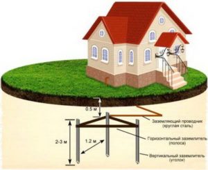
How does a ground electrode work? Mostly the elements in the grounded loop are used in the form of steel rods. They are mounted in the soil and connected to each other by a steel plate or strip. The resulting structure is connected by a cable or a similar steel plate.
![]()
The depth of metal rods directly depends on the depth of groundwater. The closer to the surface they will be located groundwater, the less deeply the rods need to be installed.
Main design parameters of the grounded loop:
- Ground loop columns, taking into account resistance, are made in various configurations:
- pipes;
- reinforcement having a smooth structure;
- I-beams.
The installation of the rod in the ground takes place taking into account its shape and the softness of the soil; in addition, the recommended cross-sectional area should be at least 1.5 cm2.
- The rods are placed in the ground in various forms, such as:
- triangular diagram;
- in the form of a rectangle;
- square.
The choice of installation form determines the working area of the ground electrode. There is a type of ground loop installed around the perimeter of the building. Although the most common is the triangular installation scheme. The top points of the electrodes are welded to a metal plate.
Grounding electrodes can be installed using additional devices, but if you order specialized equipment, you can get a ready-made set of all structural elements. Often, such kits contain grounding electrodes made of copper, having a length of 1 - 1.5 m. Professional kits are distinguished by their low financial cost, reliable tools and long service life.
Types of ground loops
There are several main types of grounding systems:
Traditional grounding systems
Such a grounding system consists of one electrode located horizontally, and the other two - vertically. The first element is made from a metal strip, and the others are made from reinforcement fragments. All these elements must be checked and made sure that they are made according to the specified standard dimensions.
In the case when grounding is installed in a residential building, it is necessary to install grounding in the part where residents of the house are less likely to visit. This may be the northern part of the building, where there is more shadow and the ground remains wetter.
The disadvantages of this installation option include:
- complexity and difficulty of construction;
- most parts of the ground loop are made of ferrous metal, which is very susceptible to corrosion;
- to located in upper layers Ground equipment is affected by changes in humidity and temperature.
Deep grounding systems
This grounding system assumes the absence of many of the disadvantages of the previous type.
Manufactured in a modular-pin manner.
Its advantages include:
- higher manufacturing accuracy of all parts;
- long service life;
- any weather is not a hindrance, since the grounding electrodes are installed at a great depth;
- no need for constant maintenance;
- fairly simple grounding calculation;
- ease of installation.
After graduation installation work, it is necessary to check the operation of all equipment. Follow the calculations of the ground electrode, thereby ensuring the quality of all connections. Ground resistance measurements are carried out by employees of specialized and licensed laboratories.
External grounding systems
This grounding system has a circuit of the type that is used in transformer substations. It includes:
- vertical electrodes;
- horizontal grounding device.
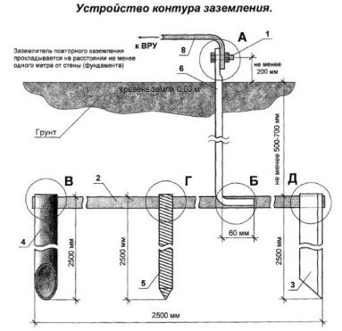
The ground electrode is made of 4 strips of 40-50 mm each. The external ground loop must be located at a distance of more than one meter from the wall. The structural element, located horizontally, is placed in a trench to a depth of 50-70 cm from the ground surface.
Connection diagrams
The most popular grounding connection schemes are:
Closed, in the shape of a triangle (Fig. 3). The main advantage can be called more stable and reliable operation. If the jumper between the rods is damaged, the circuit will still continue to work (but on the other side).
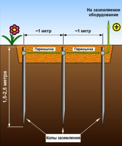
Linear (Fig. 4). Serial connection in one line of embedded metal pegs. The disadvantage of such a circuit is that if the jumper fails, the circuit will not work.
In addition to the above types of contour diagrams, you can also use the following forms:
- rectangle;
- oval
Required tools and materials:
- welding machine;
- cutting tool (grinder);
- shovel;
- perforator;
- spanners;
- resistance meter;
- current meter;
- voltage meter.
In addition to the above devices, you must use:
- The corner is made of corrosion-resistant steel, its dimensions can be 50x50, 60x60 mm. Length – more than 2 meters. It is also possible to use steel pipe, with a diameter of at least 32 mm with a wall thickness of more than 3.5-4 mm.
- Metal strips (3 pieces). Their parameters: length – 120-130 cm; width – 4-6 cm; wall thickness – 4-6 mm.
- Steel strip made of stainless material 40x4, 50x5 mm. It connects the ground loop and the porch of the house.
- Bolts M10, M8.
- The conductor is copper, with a diameter of at least 6-7 mm2.
All the above parameters must be checked using a meter.
Installation work
How to check and why you need to choose best place? This point is fundamental, since the safety of the ground loop depends on the choice of location. A mandatory condition is the installation of electrodes in a place where no one will be.
Land preparation. Using the triangle diagram as an example (Fig. 6).

The trench is dug to a depth of 50-80 cm. The sides of the triangle are 1.0-1.5 m long.
Installation of the structure:
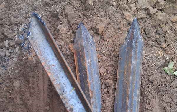
Metal rods are driven in. To make them easier to penetrate into the ground, it is recommended to sharpen them (Fig. 7);
then connecting plates are welded to the tops of the rods (Fig. 8),

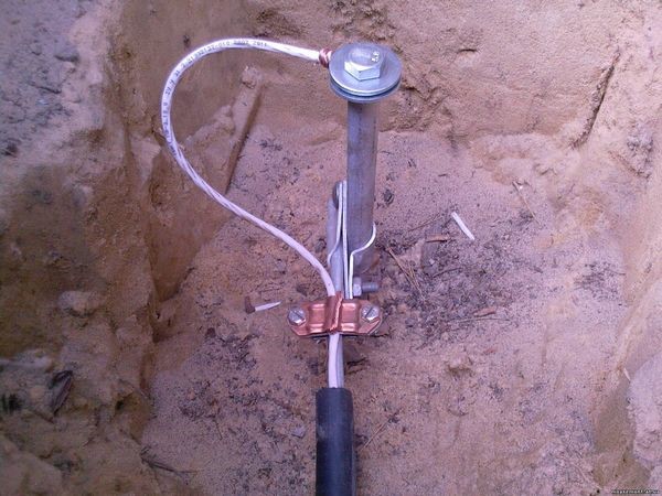
connecting the conductor to the plate through a bolt (Fig. 9), and at the very end we fill the grounding structure with earth.
At the end, it is necessary to measure the grounding and check the resistance of the entire circuit.
Video about common grounding errors
Installation of the external grounding loop is carried out according to the working drawings of the electrical installation design, which takes into account the resistivity of the soil at the installation site and the maximum permissible resistance of the grounding device in the electrical installation.
Along the route specified in the project, trenches are dug 0.7 m deep, at the bottom of which the places for immersion of the electrodes are marked so that the distances between them are approximately the same (usually at least 2.5 m), and their number corresponds to that specified in the project .
The method of immersion of electrodes depends on their shape. Round steel rods with a diameter of 12...16 mm are screwed into the ground using various devices. The PVE device (Figure 1, a) consists of an electric drill 1, transmitting rotational motion through a gearbox 2 and a clamping device 3 to the rod. A small metal strip is usually welded onto the lower end of the rod, forming a helical line. Thanks to this elementary auger, as well as the force that the worker applies to the handles of the drill, the rod quickly sinks into the ground when rotating. In the absence of a source of electricity, a PZD-12 device with a low-power internal combustion engine is used to screw in the rods (Figure 1, b).
The angles are immersed in the ground with a VM-2 vibratory hammer (Figure 1, c), which is an electric motor 1, on the shaft of which massive cast iron discs are mounted. Due to the fact that the disks are eccentrically fixed at both output ends of the shaft, when the rotor rotates, strong vibration occurs, which is transmitted through spring suspensions 2 to the base 3. To immerse the electrode, the base of the vibrating hammer is fixed to the upper end of the electrode and the engine is turned on.
Figure 1 – Tools and accessories for immersing electrodes:
a - PVE device, b - PZD-12 device,
c - vibrating hammer VM-2
After the dive vertical grounding conductors they are connected to each other by horizontal grounding conductors (a steel strip with a cross-section of at least 48 mm2 and a thickness of at least 4 mm or a steel rod with a diameter of at least 10 mm) using electric, gas or thermite welding. The parts of the grounding conductor are connected by overlap welding. The length of the overlap must be equal to the width of the conductor (for a rectangular cross-section) or six diameters (for a round cross-section), and the length of the weld must be, respectively, at least twice the width or six diameters. If there is no electricity at the work site, individual elements The ground loops are connected to each other by thermite welding.
Figure 2 – Connection of the grounding conductor to the pipeline.
a - strips, b - round conductor
For. When installing an external grounding loop using natural grounding conductors, the grounding conductors are welded to the pipelines (Figure 2). All welded joints located in the ground must be covered with a dense layer to protect against corrosion bitumen varnish. The grounding conductors themselves and the conductors connecting them should not be painted, since a layer of paint worsens the contact of the circuit with the ground.
In cases where a welded connection is difficult for some reason, screw clamps (strips at least 40 mm wide and 4 mm thick) are used to connect grounding conductors to pipelines. When installing clamps, the contact surface of the pipeline is cleaned to a metallic shine, and the surface of the clamp is tinned with POS-40 solder. The connection of the grounding conductor to the clamp must be performed by welding.
Electrical networks are rightfully considered one of the main elements of a private home. Without them, nothing can function installed equipment. However, it should be remembered that electricity itself is a source of increased danger. Therefore, in order to safely use electric current, there is special scheme grounding of a private house, combining in its grounding loop all household appliances and equipment installed in the premises.
Grounding the house:
The grounding loop has a very simple structure, which does not prevent it from performing a large number of various functions.
The most important of them are:
- Protection against electric shock if a person comes into contact with a faulty electrical device.
- High-frequency magnetic interference emitted by electrical networks and devices is reduced to normal levels.
- Provided safe operation household appliances, operating at high humidity. This applies to and dishwashers, various types of boilers and water heaters.
- Elimination of noise interference in electrical networks.
General grounding device
The main part of the grounding is the grounding loop, which is completely simple to manufacture. In a private house, it is arranged in accordance with the rules defined in the PUE.
The circuit includes three grounding electrodes that are dug into the ground. His integral part, is also a welded metal structure that acts as a bus to drain electricity.
With the help of one electrode it is impossible to create the required area providing full protection. Therefore, the design includes several grounding electrodes that are connected to each other. Located at a certain distance from each other, they completely compensate for the lack of space.
When installing the circuit structure, remember that it should not be too long distance between the electrodes. Otherwise, the surface of the optimal area will be violated. Because of this, a multiple decrease in the efficiency of the ground loop can occur.
Material for can be different kinds steel metals, as well as copper, galvanized or tinned.
Carrying out preparatory work
Before carrying out preparatory work, it is necessary to consider the design of the ground loop in more detail. It consists of vertical grounding conductors driven into the ground. Their connection to each other is carried out using horizontal grounding conductors. The entire structure is one piece with a grounding conductor connecting the circuit and the electrical panel.

Vertical grounding rods are made, most often, from steel angle, with shelf dimensions of 50x50 mm and a thickness of 5 mm. Horizontal grounding conductors can be made from 40x4 mm strip steel. For grounding conductors, round steel with a cross-section of 8 to 10 square meters is best suited. mm. Reinforcement cannot be used for these elements, since it has a hardened outer layer. In this regard, the current is distributed incorrectly across the cross section. In addition, the fittings rust much faster.
The entire structure of the ground loop is a triangle with equal sides. Exactly the same markings are made on the ground in the courtyard of the house. The recommended distance from the foundation to the contour should not exceed one meter. After the marking is completed, a trench is opened along the entire perimeter of the marking to a depth of 1 meter. The width of the trench should be convenient for welding work; for this, about 70 centimeters is sufficient. This trench is intended for laying horizontal grounding conductors.
Vertical grounding conductors are driven into the ground at each vertex of the triangle, to a depth of 2 to 3 meters. For hammering, a regular sledgehammer is used. In order for the corners to fit better into the ground, their ends must be sharpened. In places where they are clogged, you can drill holes in advance so that the corners fit into more thin layer hard ground.
Installation of the ground loop
After completing all preparatory work, you can directly install the ground loop. The corners are not driven completely into the vertices of the triangle; their edges should protrude from the ground by about 25 cm.
After driving the vertical ground electrodes into the ground, they are connected to each other using horizontal earth electrodes. After all connections, a closed circuit is formed.
For the connection, ordinary welding is used, with the help of which steel strips are welded to the ends of the corners. The connection between the corner and the strip must be welded. Application is not allowed bolted connections, since such places will gradually oxidize and contact will be lost. As a result, the functioning of the ground loop will become ineffective.
After complete assembly circuit, it must be connected to the electrical panel. The grounding conductor is welded at one end to the circuit and then laid in a trench in the direction of the electrical panel. A bolt with a diameter of 6 or 8 millimeters is welded to the end of the conductor in order to secure the wire in the shield. If steel wire is missing, then you can use the same steel strip as in the horizontal ground electrode. The strip will be even more effective than wire because it has a larger area in contact with the ground. The only problem is bending the strip as it is much stiffer than wire.
After all welding work is completed, the welded areas are treated with special compounds that protect the metal from corrosion. Under no circumstances should ordinary paints and varnishes. The circuit will stop working because it will lose connection to ground due to the high resistance created by the paint.
After backfilling the dug trenches, you can connect the ground loop to the electrical panel.
Methods for connecting the ground loop
In most cases, electricity is connected to a private house using air lines. Grounding neutral wire in these lines is carried out by TN-C system, and a phase L wire and a PEN wire are connected to the house itself, combining the functions of the neutral and working wires. Therefore, when a private house has its own grounding loop installed, it must be correctly connected to all devices and electrical installations. There are two main methods for such a connection.
Connecting home equipment to the ground loop using the TN-C-S system
The grounding system according to the TN-C option does not structurally provide for a separate protective conductor. Therefore, it is necessary to make changes and convert the existing system to TN-C-S. To do this, it is necessary to separate the combined PEN conductor in the electrical panel. You will get two separate wires: N - working, PE - protective.
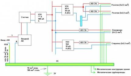
There are only two wires connected to the house from the power line, and a three-wire wiring should enter the house, which separately has phase, neutral and protection. In order to properly divide old system, a busbar is installed in the electrical panel, having with it metal bond. It will play the role of a PE grounding bus, and it is necessary to connect the PEN conductor coming from the power line side here.
The PE bus is connected to the neutral working wire N using a jumper. The N bus itself should not be connected to the electrical panel. Connection phase wire is also carried out on a separate bus, isolated from the switchboard.
After all the necessary connections have been made, it is necessary to connect the electrical panel and the ground loop. For this purpose, a stranded copper wire, one end of which is connected to the shield, and the other, using a bolt, is connected to the grounding conductor.
Connecting a house to a ground loop using a TT system
This type of connection can be made without separating the PEN conductor. The phase wire is connected to a bus isolated from the electrical panel. The PEN conductor itself is also connected to the isolated bus and subsequently plays a role neutral wire. After this, the shield body is connected to the ground loop.
![]()
Thus, the grounding diagram of a private house using this method shows a complete lack of connection between the PEN conductor and the ground loop. This method has its advantages compared to the first option. However, it is also much more expensive, since it involves the installation of additional protective devices in the form of a voltage relay.
As for the grounding loop itself, it is not at all necessary to place it in the shape of a triangle. Considering external conditions, grounding conductors can be located as desired, in the quantity that can provide minimal grounding resistance.
Checking the finished grounding system
Before starting operation, ready system grounding must be tested for its ability to perform its functions. In order to test the performance of the system, an electrical tester (Ohmmeter) is used, with which the resistance is measured. If connected to a private house electrical network, voltage 220 volts, then the grounding resistance should be no more than 30 Ohms.
IN ideal The resistance should be zero, meaning that the electricity is completely absorbed by the ground. However, in practice, this is completely impossible, therefore, special standards have been created for the electrical part of household appliances. Calculation is carried out according to resistivity and ranges from 0.5 to 60 Ohms, taking into account the characteristics of a particular ground loop.
 (1 ratings, on average: 5,00 out of 5)

