Checking the backlight of the monitor bank. How to check the performance of the inverter in a laptop
For a good image on an LCD TV, the matrix must have good lighting. In LCD TVs, backlighting is provided by a voltage inverter made from lamps, LEDs, or more advanced OLED (organic light-emitting diode) backlighting. The backlight should provide uniform illumination the entire surface of the matrix, sufficient brightness, fast reaction to change the brightness of the signal.
The most common symptom of an inverter failure is no picture when sound is present. Although another option is also possible, when the TV tries to turn on, but again goes into standby mode and no sound appears.
Describe everything possible faults inverters is impossible, therefore, in this article I will give the main ones, having understood the essence of which you can repair LCD TV voltage inverters with your own hands.
Here are some signs of a faulty inverter:
- The backlight does not turn on;
- The backlight turns on and off immediately;
- Does not turn on after a long period of inactivity;
- Flashing screen brightness;
- Uneven screen brightness.
But first, let's look at their device.
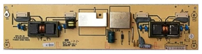
LCD TV inverter board for 4 lamps
The inverter device can be conditionally divided into functional blocks, from here it will become clear that they are all similar to each other.
Below circuit diagram The inverter belongs to lamp backlight. The lamps are connected according to a capacitive circuit, which ensures the constancy of their glow for a long time and provides effective brightness control. Transistors Q1, Q2 - turn on and turn on the inverter.

Schematic diagram of the inverter
Block (1) provides a constant voltage keyed oscillator ((4) usually consists of two field-effect transistors, for example APM4010 and APM4015), which is turned on and controlled by PWM signals. The brightness control unit (2) and PWM (3) are usually structurally made in one microcircuit. The pulse-width modulator (PWM) controls the load in the secondary circuits and, in the event of a lamp failure, does not allow the oscillator to turn on 4, which will protect against failure of the keys or the transformer.
The desired luminous flux is created by cold cathode fluorescent lamps (R) (CCFL) located behind the matrix and evenly illuminate it.
PRINCIPLE OF OPERATION
The inverter must provide several functions:
- Change direct voltage to high-voltage alternating;
- Provide brightness control;
- Stabilize the lamp current and regulate it;
- Provide short circuit and overload protection.
The matrix backlight inverter (for lamps) should provide a voltage of usually 600 volts with a load current of approximately 10 mA and provide a maximum screen brightness of about 250 cd / m2. In this case, the initial output voltage will be about 1600 V, and the protection response time will be from 1 to 1.3 s. For a confident start, the protection response time is selected 10 times more than the start time.
When voltage is applied from the power supply, the signal (usually 3-5 volts) to exit standby mode comes approximately 2 seconds after the TV is turned on from the main board and the backlight inverter goes into working condition.
The TV inverter controller provides a soft start when starting the inverter, as well as protection against short circuit and overload. If short circuit lasts less than 1 s, the inverter will continue to run, otherwise it will turn off.
PWM pulses go to the converter, usually made according to the scheme of a semi-bridge generator with self-excitation and start the DC / DC converter and voltage for the backlight appears on the secondary winding of the inverter transformer.
A small winding performs the function in the TV inverter circuit feedback.
When the lamps are “ignited” at the beginning of operation, the converter voltage increases to 1600 V, and only then the inverter switches to operating mode. A faulty lamp, a capacitor in the secondary circuit, or a short circuit in the secondary winding leads to a breakdown in generation.
LCD TV inverter voltage is usually 24 or 48 volts (for large diagonal). The backlight of a laptop is usually powered by a power supply voltage of 18 - 19 volts.
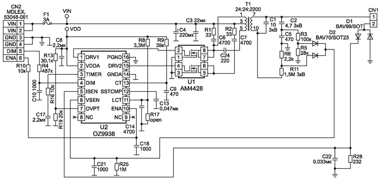
The board of such an inverter has small size and is located at the bottom of the screen. In this case, the U2 OZ9938 controller controls the U1 AM4428 keys, the CN1 contact goes to the lamp. Power goes through the VIN contacts, minus GND, brightness and power control to the DIM and ENA contacts.
LCD INVERTER
In principle, there is no particular difference other than a change in voltage. For example, an LCD TV inverter often uses a voltage of 12 volts. The output can vary from 60 to 100 volts in general. This variation depends on the diagonal of the TV and, accordingly, the number of LEDs used for backlighting.
REPAIR
Anyone with a little knowledge of electronics and working with a soldering iron and a multimeter can repair the inverter with their own hands, since there is nothing extraordinary in it.
According to the breakdowns, probably to say, there are no main ones, everything breaks down. Lamps, keys, transformers, controllers burn out.
Most often, the backlight inverter fails due to breakdowns. electrolytic capacitors in the power supply and power filters of the inverter itself. Losing capacity, swelling and closing the power circuit, they lower the voltage. The keys start to work with more overload and burn out.
IN LCD TVs more often the diodes themselves burn out. When repairing a TV, you can replace the entire LED strip or check each one and replace it individually. For example, you have 3 stripes on your TV LED strips 7 diodes each. It is known that the voltage of their supply is 70 volts. We divide and get 3.3 volts, we are looking for one with a power of 1 watt to ensure normal brightness and make a replacement.
Models modern inverters very diverse, but the principles of their construction and operation are almost the same, and this simplifies their repair.
The material is provided by the publishing house Repair and Service
General provisions
Let's make a reservation right away that the article is related to inverters for CCFL lamps. At this time, instead of CCFL backlight, it is actively used LED backlight, where LEDs of the brands LATWT470RELZK SBWVT120E PT30W45 V1 and others are considered the best.
For the operation of the LCD panel, the light source is of paramount importance, the luminous flux of which, passed through the structure of the liquid crystal, forms an image on the monitor screen. For creating luminous flux cold cathode fluorescent lamps (CCFL) are used, which are located at the edges of the monitor (usually at the top and bottom) and with the help of frosted diffuser glass evenly illuminate the entire surface of the LCD matrix. The "ignition" of the lamps, as well as their power in the operating mode, is provided by inverters. The inverter must ensure reliable start-up of lamps with voltages above 1500 V and their stable operation for a long time at operating voltages from 600 to 1000 V. Lamps in LCD monitors are connected according to a capacitive circuit (see Fig. 1). The working point of a stable glow (RT - on the graph) is located on the line of intersection of the load straight line with the graph of the dependence of the discharge current on the voltage applied to the lamps. The inverter in the monitor creates conditions for a controlled glow discharge, and the operating point of the lamps is on the flat part of the curve, which makes it possible to achieve a constant glow for a long time and provide effective brightness control. You can buy inverters for LCD TVs and monitors in the Dalincom online store.
Rice. 1. Graph of the position of the operating current of a stable glow of the lamps
The inverter performs the following functions:
converts direct voltage (usually +12 V) into high-voltage alternating;
stabilizes the lamp current and, if necessary, regulates it;
provides brightness control;
matches the output stage of the inverter with the input impedance of the lamps;
Provides short circuit and overload protection.
No matter how diverse the market of modern inverters is, the principles of their construction and operation are almost the same, which simplifies their repair.
The block diagram of the inverter is shown in fig. 2. The block of standby mode and turning on the inverter is made in this case on the keys Q1, Q2. The LCD monitor takes some time to turn on, so the inverter also turns on 2 ... 3 seconds after the monitor is switched to the operating mode. ON/OFF voltage is supplied from the main board and the inverter enters the running mode. The same block ensures that the inverter turns off when the monitor enters one of the power saving modes. When a positive ON voltage (3 ... 5 V) is applied to the base of transistor Q1, + 12V voltage is supplied to the main inverter circuit - a brightness control unit and a PWM controller.

Rice. 2. Structural diagram of the inverter
The block for monitoring and controlling the brightness of the glow of lamps and PWM (3 in Fig. 2) is made according to the scheme of an error amplifier (OA) and a PWM pulse shaper. It receives the dimmer voltage from the main monitor board, after which this voltage is compared with the feedback voltage, and then an error signal is generated that controls the frequency of the PWM pulses. These pulses are used to control the DC / DC converter (1 in Fig. 2) and synchronize the operation of the converter-inverter. The amplitude of the pulses is constant and is determined by the supply voltage (+12 V), and their frequency depends on the brightness voltage and the threshold voltage level.
DC / DC converter (1) provides a constant (high) voltage, which is supplied to the oscillator. This generator is turned on and controlled by PWM pulses of the control unit (3).
The level of the output AC voltage of the inverter is determined by the parameters of the circuit elements, and its frequency is determined by the dimmer and the characteristics of the backlight lamps. The inverter converter is usually a self-excited generator. Both single-stroke and two-stroke circuits can be used.
The protection unit (5 and 6) analyzes the level of voltage or current at the output of the inverter and generates feedback voltages (OS) and overloads, which enter the control unit (2) and PWM (3). If the value of one of these voltages (in the event of a short circuit, inverter overload, low supply voltage level) exceeds the threshold value, the oscillator stops its operation.
As a rule, on the screen, the control unit, PWM and brightness control unit are combined in one chip. The converter runs on discrete elements with a load in the form pulse transformer, additional winding which is used to switch the trigger voltage.
All main components of inverters are made in SMD component cases.
Exists a large number of inverter modifications. The use of one type or another is determined by the type of LCD panel used in this monitor, so inverters of the same type may be found in different manufacturers.
Consider the most commonly used types of inverters, as well as their characteristic faults.
EMAX type inverter PLCD2125207A
This inverter is used in Proview, Acer, AOC, BENQ and LG LCD monitors with a screen size of 15 inches or less. It is built according to a single-channel scheme with a minimum number of elements (Fig. 3). With an operating voltage of 700 V and a load current of 7 mA, using two lamps, the maximum screen brightness is about 250 cd / m 2. The starting output voltage of the inverter is 1650V, the protection response time is from 1 to 1.3s. At idle, the output voltage is 1350V. The greatest depth of brightness is achieved by changing the control voltage DIM (pin 4 connector CON1) from 0 (maximum brightness) to 5 V (minimum brightness). The inverter is made in the same way. by SAMPO.
Rice. 3. Schematic diagram of the inverter PLCD2125207A
Circuit diagram description
Voltage +12 V is supplied to the cont. 1 of the CON1 connector and through the F1 fuse - on the pin. 1-3 assemblies of Q3 (source of the field-effect transistor). The step-up DC / DC converter is assembled on the elements Q3-Q5, D1, D2, Q6. In operating mode, the resistance between the source and drain of transistor Q3 does not exceed 40 mOhm, while a current of up to 5 A is passed to the load. The converter is controlled by a brightness and PWM controller, which is made on a U1 chip of the TL5001 type (similar to FP5001) from Feeling Tech. The main element of the controller is a comparator, in which the voltage of the sawtooth voltage generator (pin 7) is compared with the voltage of the UO, which in turn is determined by the ratio between the reference voltage of 1 V and the total feedback and brightness voltage (pin 4). The frequency of the sawtooth voltage of the internal generator (about 300 kHz) is determined by the value of the resistor R6 (connected to pin 7 of U1). From the output of the comparator (pin 1), PWM pulses are taken, which are fed to the DC / DC converter circuit. The controller also provides short circuit and overload protection. In the event of a short circuit at the output of the inverter, the voltage across the divider R17 R18 increases, it is rectified and fed to the pin. 4U1. If the voltage becomes 1.6V, the controller's protection circuit is activated. The protection threshold is determined by the value of the resistor R8. Capacitor C8 provides a "soft" start when starting the inverter or after the end of the short circuit. If the short circuit lasts less than 1 s (the time is determined by the capacitance of the capacitor C7), then normal work inverter continues. Otherwise, the inverter will stop running. For a reliable start of the converter, the protection response time is chosen such that it exceeds the start and "ignition" time of the lamps by 10 ... 15 times. When the output stage is overloaded, the voltage at the right terminal of the inductor L1 increases, the zener diode D2 begins to pass current, the transistor Q6 opens and the threshold for operating the protection circuit decreases. The converter is made according to the scheme of a half-bridge generator with self-excitation on transistors Q7, Q8 and transformer PT1. When the ON / OFF voltage (3 V) is received from the main monitor board, transistor Q2 opens and power is supplied to the controller U1 (+12 V at pin 2). PWM pulses with pin. 1 U1 through transistors Q3, Q4 enter the gate of Q3, thereby starting the DC / DC converter. In turn, power is supplied from it to the autogenerator. After that, a high-voltage voltage appears on the secondary winding of the transformer RT1. AC voltage, which is supplied to the backlight lamps. Winding 1-2 RT1 acts as a feedback oscillator. While the lamps are not turned on, the output voltage of the inverter rises to the start voltage (1650V), and then the inverter enters the operating mode. If the lamps cannot be ignited (due to a break, “exhaustion”), a spontaneous generation failure occurs.
Malfunctions of the PLCD2125207A inverter and the procedure for their elimination
Backlights do not turn on
Check the supply voltage +12 V at the pin. 2U1. If not, check fuse F1, transistors Q1, Q2. If fuse F1 is faulty, before replacing it, check transistors Q3, Q4, Q5 for a short circuit.
Then they check the ENB or ON / OFF signal (pin 3 of the CON1 connector) - its absence may be due to a malfunction of the main monitor board. Check it out in the following way: supply a control voltage of 3 ... 5 V to the ON / OFF input from an independent power source or through a divider from a 12V source. If at the same time the lamps turn on, then the main board is faulty, otherwise the inverter.
If there is a supply voltage and a turn-on signal, but the lamps do not light, then an external inspection of the transformer PT1, capacitors C10, C11 and lamp connectors CON2, CON3 is carried out, darkened and melted parts are replaced. If at the time of switching on the pin. 11 of the PT1 transformer, voltage pulses appear for a short time (the oscilloscope probe is connected through a divider in advance, before the monitor is turned on), and the lamps do not light up, then check the condition of the lamp contacts and the absence of mechanical damage on them. The lamps are removed from the seats, after unscrewing the screw securing their housing to the matrix housing, and, together with the metal housing in which they are installed, they are evenly and without distortions removed. In some monitor models (Acer AL1513 and BENQ), the lamps have L-shape and encircle the LCD panel around the perimeter, and careless actions during disassembly can damage them. If the lamps are damaged or darkened (which indicates the loss of their properties), they are replaced. Lamps can only be replaced with ones similar in power and parameters, otherwise, either the inverter will not be able to “ignite” them, or an arc discharge will occur, which will quickly disable the lamps.
Lamps turn on for a short time (about 1 second) and then turn off immediately
In this case, the protection against short circuit or overload in the secondary circuits of the inverter is most likely triggered. Eliminate the reasons for the operation of the protection, check the health of the transformer RT1, capacitors C10 and C11 and the feedback circuit R17, R18, D3. They check the zener diode D2 and the transistor Q6, as well as the capacitor C8 and the divider R8 R9. If the voltage on the pin. 5 less than 1 V, then replace the capacitor C7 (preferably with tantalum). If all the above actions do not work, replace the U1 chip.
Turning off the lamps can also be associated with a breakdown in the generation of the converter. To diagnose this malfunction, instead of lamps, an equivalent load is connected to the CON2, CON3 connectors - a resistor with a nominal value of 100 kOhm and a power of at least 10 W. A 10 ohm measuring resistor is connected in series with it. Devices are connected to it and the oscillation frequency is measured, which should be in the range from 54 kHz (at maximum brightness) to 46 kHz (at minimum brightness) and the load current from 6.8 to 7.8 mA. To control the output voltage, connect a voltmeter between pin 11 of the PT1 transformer and the output of the load resistor. If the measured parameters do not correspond to the nominal, they control the magnitude and stability of the supply voltage at the inductor L1, and also check the transistors Q7, Q8, C9. If, when the right (according to the diagram) assembly diode D3 is disconnected from the resistor R5, the screen lights up, then one of the lamps is faulty. Even with one working lamp, the brightness of the image is enough for the operator to work comfortably.
The screen flickers intermittently and the brightness is unstable
Check the stability of the brightness voltage (DIM) on the cont. 4 connectors CON1 and after the resistor R3, having previously turned off the feedback (resistor R5). If the control voltage at the connector is unstable, then the main monitor board is faulty (the test is carried out in all available monitor operating modes and over the entire brightness range). If the voltage is unstable at the pin. 4 controllers U1, then check its DC mode in accordance with Table. 1, while the inverter must be in the operating mode. The defective chip is replaced.
Table 1
They check the stability and amplitude of oscillations of their own sawtooth pulse generator (vyv.7), the signal swing should be from 0.7 to 1.3 V, and the frequency should be about 300 kHz. If the voltage is not stable - replace R6 or U1.
The instability of the inverter may be due to the aging of the lamps or their damage (periodic contact failure between the supply wires and the lamp leads). To check this, as in the previous case, a load equivalent is connected. If the inverter works stably, then the lamps must be replaced.
After a while (from a few seconds to a few minutes), the image disappears
The protection circuit is not working properly. Check and, if necessary, replace the capacitor C7 connected to the pin. 5 of the controller, control the DC mode of the controller U1 (see previous fault). The stability of the lamps is checked by measuring the level of sawtooth pulses at the output of the feedback circuit, on the right anode D3 (peak about 5 V) at medium brightness setting (50 units). If there are "emissions" of voltage, check the serviceability of the transformer and capacitors C9, C11. In conclusion, the stability of the PWM controller circuit U1 is checked.
Inverter type DIVTL0144-D21 from SAMPO
The schematic diagram of this inverter is shown in fig. 4. It is used to power the backlight lamps of 15-inch SUNGWUN, SAMSUNG, LG-PHILIPS, HITACHI matrices, which are used in PROVIEW, ACER, BENQ, SAMSUNG, LG monitors. Operating voltage - 650 V at a load current of 7.5 mA (at maximum brightness) and 4.5 mA - at minimum. The starting voltage ("ignition") is 1900 V, the frequency of the supply voltage of the lamps is 55 kHz (at medium brightness). The dimming signal level is between 0 (maximum) and 5 V (minimum). Protection operation time - 1…4 s.
Rice. 4.
As a controller and PWM, a U201 chip of type BA9741 from ROHM (its analogue TL1451) is used. It is a two-channel controller, but in this case only one channel is used.
When the monitor is connected to the network, a voltage of +12 V is supplied to pin 1-3 of the Q203 transistor assembly (the source of the field-effect transistor). When the monitor is turned on, the ON / OFF inverter start signal (+3 V) comes from the main board and opens transistors Q201, Q202. Thus, a voltage of +12 V is applied to the pin. 9 controller U201. After that, the internal sawtooth voltage generator begins to work, the frequency of which is determined by the values of the elements R204 and C208 connected to the pin. 1 and 2 chips. On pin 10 of the microcircuit, PWM pulses appear, which are fed to the Q203 gate through an amplifier on transistors Q205, Q207. On the output 5-8 Q203 generates a constant voltage, which is supplied to the oscillator (on the elements Q209, Q210, PT201). A sinusoidal voltage with a swing of 650 V and a frequency of 55 kHz (at the moment of "ignition" of the lamps it reaches 1900 V) from the output of the converter through the connectors CN201, CN202 is supplied to the backlight lamps. On elements D203, R220, R222, a circuit for generating a protection signal and a “soft” start is made. At the moment the lamps are turned on, the energy consumption in the primary circuit of the inverter increases and the voltage at the output of the DC / DC converter (Q203, Q205, Q207) grows, the zener diode D203 begins to conduct current, and part of the voltage from the divider R220 R222 goes to pin 11 of the controller, increasing the by the very threshold of the protection circuit for the start time.
The stability and brightness of the glow of the lamps, as well as protection against short circuits, is provided by a feedback circuit on the elements D209, D205, R234, D207, C221. The feedback voltage is supplied to the pin. 14 microcircuits (direct input of the error amplifier), and the brightness voltage from the main monitor board (DIM) - to the inverse input of the UO (pin 13), determining the PWM pulse frequency at the controller output, and hence the output voltage level. At minimum brightness (DIM voltage is 5 V) it is 50 kHz, and at maximum brightness (DIM voltage is zero) it is 60 kHz.
If the feedback voltage exceeds 1.6 V (pin 14 of the U201 chip), the protection circuit is activated. If the short circuit in the load lasts less than 2 s (this is the charge time of the capacitor C207 from the reference voltage of +2.5 V - pin 15 of the microcircuit), the inverter is restored, which ensures a reliable start of the lamps. In the event of a long short circuit, the inverter will turn off.
Malfunctions of the DIVTL0144-D21 inverter and methods for their elimination
Lamps do not light up
Check the presence of voltage +12 V on the pin. 1-3 Q203, fuse F1 is good (installed on the main monitor board). If the fuse is defective, then before installing a new one, transistors Q201, Q202, as well as capacitors C201, C202, C225 are checked for a short circuit.
They check the presence of ON / OFF voltage: when the operating mode is turned on, it should be equal to 3V, and when it is turned off or switched to standby mode, it should be zero. If there is no control voltage, check the main board (the microcontroller of the LCD monitor controls the inverter). If all of the above voltages are normal, and the PWM pulses on the pin. 10, there are no V201 microcircuits, they check the zener diodes D203 and D201, the PT201 transformer (can be determined by visual inspection by a darkened or melted case), capacitors C215, C216 and transistors Q209, Q210. If there is no short circuit, then check the serviceability and rating of capacitors C205 and C207. If the items listed above are OK, replace the U201 controller. Note that the lack of glow of the backlight lamps may be due to their breakage or mechanical failure.
Lamps turn on and off briefly
If the illumination persists for 2 s, then the feedback circuit is faulty. If, when disconnected from the circuit of elements L201 and D207, pin. 7 of the U201 microcircuit, PWM pulses appear, then either one of the backlight lamps or the feedback circuit is faulty. In this case, check the zener diode D203, diodes D205, D209, D207, capacitors C221, C219, as well as the inductor L202. Control the voltage at the output. 13 and 14 U201. In operating mode, the voltage at these pins should be the same (about 1 V - at medium brightness). If the voltage on the pin. 14 is significantly lower than on pin. 13, then check the diodes D205, D209 and the lamps for an open circuit. With a sharp increase in voltage at the pin. 14 U201 chips (above 1.6V) check the elements PT1, L202, C215, C216. If they are working, replace the U201 chip. When replacing it with an analog (TL1451), the threshold voltage is checked at the pin. 11 (1.6 V) and, if necessary, select the value of the elements C205, R222. By selecting the values of the elements R204, C208, the frequency of the sawtooth pulses is set: on the pin. 2 chips should be about 200 kHz.
The backlight turns off after a while (a few seconds to a few minutes) after the monitor is turned on
First check the capacitor C207 and the resistor R207. Then they check the health of the contacts of the inverter and backlights, capacitors C215, C216 (replacement), transformer PT201, transistors Q209, Q210. Control the threshold voltage on the pin. 16 V201 (2.5V), if it is underestimated or absent, replace the microcircuit. If the voltage on the pin. 12 above 1.6V, check the capacitor C208, otherwise also replace U201.
Brightness spontaneously changes (blinks) in the entire range or in certain monitor modes
If the problem occurs only in some resolution modes and within a certain range of brightness changes, then the problem is with the main monitor board (memory or LCD controller). If the brightness spontaneously changes in all modes, then the inverter is faulty. Check the brightness control voltage (on pin 13 U201 - 1.3 V (at medium brightness), but not higher than 1.6 V). In case the voltage at the DIM pin is stable, and at the pin. 13 - no, replace the U201 chip. If the voltage on the pin. 14 is unstable or underestimated (less than 0.3 V at minimum brightness), then instead of lamps, a load equivalent is connected - a resistor with a nominal value of 80 kOhm. If the defect persists, replace the U201 chip. If this replacement does not help, replace the lamps, and also check the health of their contacts. They measure the voltage at pin 12 of the U201 microcircuit, in operating mode it should be about 1.5V. If it is below this limit, check elements C209, R208.
Note.In inverters from other manufacturers (EMAX, TDK), made in a similar way, but using other components (except for the controller), instead of SI443 -> D9435, 2SC5706 -> 2SD2190, the voltage at the pins of the U201 chip can vary within ±0, 3 V.
This inverter (its schematic diagram is shown in Fig. 5) is used in 17-inch ACER, ROVER SCAN monitors with matrices SAMSUNG, and its simplified version ( rice. 6 ) - in 15-inch LG monitors with an LG-PHILIPS matrix. The circuit is implemented on the basis of a 2-channel PWM controller from the company OZ960 O2MICRO with 4 outputs of control signals. As power keys transistor assemblies of the FDS4435 type (two field-effect transistors with a p-channel) and FDS4410 (two field-effect transistors with an n-channel) are used. The circuit allows you to connect 4 lamps, which provides increased brightness of the LCD panel backlight.

Rice. 5
The inverter has the following features:
- supply voltage - 12 V;
– nominal current in the load of each channel - 8 mA;
- output voltage frequency - from 30 kHz (at minimum brightness) to 60 kHz (at maximum brightness). The maximum brightness of the screen glow with this inverter is 350 cd / m 2;
– protection response time - 1…2 s.
When the monitor is turned on, +12 V voltage is supplied to the inverter connector - to power the Q904-Q908 switches and +6 V - to power the U901 controller (in the version for the LG monitor, this voltage is formed from +12 V voltage, see the diagram in Fig. 6) . The inverter is in standby mode. The turn-on voltage of the ENV controller is supplied to the pin. 3 chips from the microcontroller of the main monitor board. The PWM controller has two identical outputs for powering two inverter channels: pin. 11, 12 and vyv. 19, 20 (Fig. 5 and 6). The frequency of the generator and PWM are determined by the values of the resistor R908 and capacitor C912 connected to the pin. 17 and 18 chips ( rice. 5 ). Resistor divider R908 R909 determines the initial threshold of the sawtooth voltage generator (0.3 V). On the capacitor C906 (pin 7 U901), the threshold voltage of the comparator and the protection circuit is formed, the response time of which is determined by the value of the capacitor C902 (pin 1). The protection voltage against short circuit and overload (when the backlight breaks) is supplied to the pin. 2 chips. The U901 controller has a built-in soft start circuit and an internal regulator. The launch of the soft start circuit is determined by the voltage at the pin. 4 (5V) controllers.
Rice. 6
Voltage transformer direct current in the high-voltage supply voltage of the lamps, it is made on two pairs of p-type FDS4435 and n-type FDS4410 transistor assemblies and is forcedly triggered by PWM pulses. A pulsating current flows in the primary winding of the transformer and secondary windings T901, the supply voltage of the backlight lamps connected to the J904-J906 connectors appears. To stabilize the output voltages of the inverter, the feedback voltage is fed through the full-wave rectifiers Q911-Q914 and the integrating circuit R938 C907 C908 and is fed to the pin in the form of sawtooth pulses. 9 controller U901. When one of the backlight lamps breaks, the current increases through the divider R930 R932 or R931 R933, and then the rectified voltage is supplied to the pin. 2 controllers exceeding the set threshold. Thus, the formation of PWM pulses on the pin. 11, 12 and 19, 20 U901 is blocked. In the event of a short circuit in the circuits C933 C934 T901 (winding 5-4) and C930 C931 T901 (winding 1-8), voltage spikes occur, which are rectified by Q907-Q910 and also fed to the pin. 2 controllers - in this case, protection is triggered and the inverter turns off. If the short circuit time does not exceed the charge time of the capacitor C902, the inverter continues to operate normally.
The fundamental difference between the circuits in Fig. 5 and 6 in that in the first case a more complex soft start circuit is used (the signal is sent to pin 4 of the microcircuit) on transistors Q902, Q903. In the diagram in fig. 6, it is implemented on the capacitor C10. It also uses assemblies of field-effect transistors U2, U3 (p- and n-type), which simplifies their power matching and ensures high reliability in circuits with two lamps. In the diagram in fig. 5, field-effect transistors Q904-Q907 are used, connected in a bridge circuit, which increases the output power of the circuit and the reliability of operation in start-up modes and at high currents.
Inverter Faults and Solutions
Lamps do not turn on
Check the presence of supply voltage +12 and +6 V on pin. Vinv, Vdd of inverter connector respectively ( rice. 5 ). In their absence, check the health of the main monitor board, assemblies Q904, Q905, zener diodes Q903-Q906 and capacitor C901.
Check the supply of +5 V inverter turn-on voltage to pin. Ven when putting the monitor into working mode. You can check the health of the inverter using an external power source by applying a voltage of 5 V to the pin. 3 U901 chips. If the lamps turn on at the same time, then the cause of the malfunction is in the main board. Otherwise, the elements of the inverter are checked, and the presence of PWM signals on the pin is monitored. 11, 12 and 19, 20 U901 and, in their absence, replace this chip. They also check the health of the windings of the T901 transformer for an open and short circuit of the turns. When a short circuit is detected in the secondary circuits of the transformer, the serviceability of the capacitors C931, C930, C933 and C934 is first checked. If these capacitors are in good condition (you can simply unsolder them from the circuit), and a short circuit occurs, open the place where the lamps are installed and check their contacts. Burnt contacts are repaired.
The backlights flash for a short time and immediately go out
Check the serviceability of all lamps, as well as their connection circuits with connectors J903-J906. You can check the health of this circuit without disassembling the lamp unit. To do this, the feedback circuits are turned off for a short time, sequentially soldering the diodes D911, D913. If at the same time the second pair of lamps turns on, then one of the lamps of the first pair is faulty. Otherwise, the PWM controller is faulty or all lamps are damaged. You can also check the inverter’s performance by using an equivalent load instead of lamps - a 100 kΩ resistor connected between the cont. 1, 2 connectors J903, J906. If in this case the inverter does not work and there are no PWM pulses on the pin. 19, 20 and 11, 12 U901, then check the voltage level at the pin. 9 and 10 microcircuits (1.24 and 1.33 V, respectively. In the absence of the indicated voltages, the elements C907, C908, D901 and R910 are checked. Before replacing the controller microcircuit, the rating and serviceability of the capacitors C902, C904 and C906 are checked.
Inverter turns off spontaneously after a while (a few seconds to a few minutes)
Check the voltage at the output. 1 (about 0 V) and 2 (0.85 V) U901 in operating mode, if necessary, change the capacitor C902. With a significant difference in the voltage at the pin. 2 from the nominal value, check the elements in the short circuit and overload protection circuit (D907-D910, C930-C935, R930-R933) and, if they are in good condition, replace the controller chip. Check the voltage ratio on the pin. 9 and 10 microcircuits: on pin. 9 voltage should be lower. If this is not the case, check the capacitive divider C907 C908 and the feedback elements D911-D914, R938.
Most often, the cause of such a malfunction is caused by a defect in the capacitor C902.
The inverter is unstable, there is a flashing of the backlight lamps
Check the performance of the inverter in all modes of operation of the monitor and in the entire range of brightness. If instability is observed only in some modes, then the main monitor board (brightness voltage generation circuit) is faulty. As in the previous case, an equivalent load is included and a milliammeter is installed in the circuit break. If the current is stable and equal to 7.5 mA (at minimum brightness) and 8.5 mA (at maximum brightness), then the backlight lamps are faulty and must be replaced. Also check the elements of the secondary circuit: T901, C930-C934. Then check the stability of rectangular pulses (average frequency - 45 kHz) on the pin. 11, 12 and 19, 20 U901 chips. The DC component on them should be 2.7 V at the P-outputs and 2.5 V at the N-outputs). Check the stability of the sawtooth voltage at the pin. 17 chips and, if necessary, replace C912, R908.
Schematic diagram of the SAMPO inverter is shown in fig. 7. It is used in 17-inch SAMSUNG, AOC monitors with SANYO matrices, monitors "Proview SH 770" and "MAG HD772". There are several modifications to this scheme. The inverter generates an output voltage of 810V at rated current through each of the four fluorescent lamps(about 6.8mA). The starting output voltage of the circuit is 1750V. The frequency of the converter at an average brightness of 57 kHz, while achieving a monitor screen brightness of up to 300 cd/m 2 . The response time of the inverter protection circuit is from 0.4 to 1 s.

Rice. 7
The basis of the inverter is the TL1451AC chip (analogues - TI1451, BA9741). The microcircuit has two control channels, which allows you to implement a power supply circuit for four lamps. When the monitor is turned on, +12 V voltage is supplied to the inputs of +12 V voltage converters (sources of field-effect transistors Q203, Q204). The dimming voltage DIM is supplied to the pin. 4 and 13 microcircuits (inverted inputs of error amplifiers). When a turn-on voltage of 3 V (pin ON / OFF) is received from the main board of the monitor, transistors Q201 and Q202 open and on the pin. 9 (VCC) of the U201 chip, +12 V is supplied. 7 and 10, rectangular PWM pulses appear, which are fed to the bases of transistors Q205, Q207 (Q206, Q208), and from them to Q203 (Q204). As a result, voltages appear on the right terminals of the inductors L201 and L202 according to the scheme, the value of which depends on the duty cycle of the PWM signals. These voltages feed the oscillator circuits made on transistors Q209, Q210 (Q211, Q212). On primary windings 2-5 transformers RT201 and RT202, respectively, a pulsed voltage appears, the frequency of which is determined by the capacitance of capacitors C213, C214, the inductance of the windings of 2-5 transformers RT201, RT202, as well as the level of the supply voltage. When adjusting the brightness, the voltage at the outputs of the converters changes and, as a result, the frequency of the generators. The amplitude of the output pulses of the inverter is determined by the supply voltage and the state of the load.
Autogenerators are made according to a half-bridge circuit, which provides protection against high currents in the load and a break in the secondary circuit (turning off lamps, breakage of capacitors C215-C218). The heart of the protection circuit is in the U201 controller. In addition, the protection circuit includes elements D203, R220, R222 (D204, R221, R223), as well as a feedback circuit D205 D207 R240 C221 (D206 D208 R241 C222). When the voltage at the output of the converter rises, the zener diode D203 (D204) breaks through and the voltage from the divider R220, R222 (R221, R223) is fed to the input of the overload protection circuit of the controller U201 (pin 6 and 11), increasing the protection threshold for the time the lamps start. Feedback circuits rectify the voltage at the output of the lamps and it goes to the direct inputs of the controller error amplifiers (pin 3, 13), where it is compared with the dimming voltage. As a result, the frequency of the PWM pulses changes and the brightness of the lamps is maintained at a constant level. If this voltage exceeds 1.6 V, then the short circuit protection circuit will start, which will work during the charge of the capacitor C207 (about 1 s). If the short circuit lasts less than this time, the inverter will continue to operate normally.
SAMPO Inverter Faults and Solutions
The inverter does not turn on, the lamps do not light up
Check the presence of +12V voltage and the active state of the ON / OFF signal. In the absence of + 12V, they check its presence on the main board, as well as the serviceability of transistors Q201, Q202, Q205, Q207, Q206, Q208) and Q203, Q204. If there is no ONN / OFF inverter turn-on voltage, it is supplied from an external source: + 3 ... 5V through a 1 kΩ resistor to the base of transistor Q201. If the lamps turn on at the same time, then the malfunction is related to the formation of the inverter turn-on voltage on the main board. Otherwise, check the voltage at the pin. 7 and 10 U201. It should be equal to 3.8V. If the voltage at these pins is 12V, then the U201 controller is faulty and must be replaced. Check the reference voltage at the pin. 16 U201 (2.5 V). If it is zero, check the capacitors C206, C205 and, if they are working, replace the controller U201.
Check the presence of generation on the output. 1 (sawtooth voltage swing 1 V) and, in its absence, capacitor C208 and resistor R204.
Lights come on but then go out immediately (within less than 1 second)
Check the health of the zener diodes D201, D202 and transistors Q209, Q210 (Q211, Q212). In this case, one of the pairs of transistors may be faulty. They check the overload protection circuit and the health of the zener diodes D203, D204, as well as the values of resistors R220, R222 (R221, R223) and capacitors C205, C206. Check the voltage at the output. 6 (11) controller chips (2.3 V). If it is underestimated or equal to zero, check the elements C205, R222 (C206, R223). In the absence of PWM signals on the pin. 7 and 10 U201 microcircuits measure the voltage at the pin. 3 (14). It should be 0.1 ... 0.2V more than the pin. 4 (13), or the same. If this condition is not met, check the elements D206, D208, R241. When carrying out the above measurements, it is better to use an oscilloscope. The inverter shutdown may be due to an open or mechanical damage one of the lamps. To test this assumption (in order not to disassemble the lamp assembly), the + 12V voltage of one of the channels is turned off. If at the same time the monitor screen starts to glow, then the disabled channel is faulty. They also check the serviceability of transformers RT201, RT202 and capacitors C215-C218.
The lamps spontaneously turn off after a while (from units of seconds to minutes)
As in previous cases, they check the elements of the protection circuit: capacitors C205, C206, resistors R222, R223, as well as the voltage level at the pin. 6 and 11 of the U201 chip. In most cases, the cause of the defect is caused by a malfunction of the capacitor C207 (which determines the protection response time) or the controller U201. Measure the voltage at the inductors L201, L202. If the voltage rises steadily during the operating cycle, check transistors Q209, Q210 (Q211, Q212), capacitors C213, C214 and zener diodes D203, D204.
The screen flickers intermittently and the brightness of the screen backlight is unstable
Check the health of the feedback circuit and the operation of the controller error amplifier U201. Measure the voltage at the output. 3, 4, 12, 13 chips. If the voltage at these terminals is below 0.7V, and at the pin. 16 below 2.5V, then replace the controller. Check the health of the elements in the feedback circuit: diodes D205, D207 and D206, D208. Connect load resistors with a nominal value of 120 kΩ to the CON201-CON204 connectors, check the level and stability of the voltages on the pin. 14 (13), 3 (4), 6 (11). If the inverter operates stably with the load resistors connected, replace the backlight lamps.
In this note, we will tell you how you can check the LCD screen inverter in a laptop.
The failure of the inverter is very similar to the symptoms of a faulty backlight. In both cases, the screen becomes dark and the image becomes very faint, barely visible in bright light.
If you suspect that it is the inverter that has failed, there are only two reliable ways to check this. The first is to install a working inverter, the second is to connect a known-good backlight to the old one, if it lights up, then the inverter is working.
In most cases, the easiest second method is to test the laptop with a working backlight. Why? Since the backlight is almost universal. The same backlight will work with many different inverters, most importantly the same connectors. We'll talk about these connectors below.
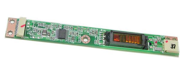
The inverter is usually located inside the panel under the LCD's plastic bezel. In most laptops, the inverter can be accessed by removing this bezel. The inverter board has connectors at both ends. On the left side, the inverter is connected to the LCD cable. On the right side, the inverter is connected to a backlight that is installed inside the matrix.
To make sure the inverter is getting power from the motherboard, you can test it with a multimeter. In our case, we connect the “+” of the multimeter to 1 pin of the connector, “-” can be connected to the copper hole with which the inverter is attached to the cover. As a result, we get about 19.4V DC, this indicates that power is supplied to the inverter.
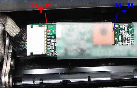
ATTENTION! If you accidentally short the pins while testing, you could damage the inverter or even the motherboard. Proceed at your own risk!
So the inverter is getting power from the motherboard, but the screen is still dark. Apparently, this is either a malfunction of the inverter, or the backlight. It is necessary to check the operation with a working backlight.
Here's what to do:
1. 1. Turn off the LCD screen with right side from the inverter.
2. 2. Connect the working backlight as shown in the picture below. Please note that the test backlight is shorter than on the matrix, but this will not interfere with the test.
Possible test results:
1. 1. If the backlight lights up, then a malfunction has been found, and it is necessary to replace the lamp installed in the matrix. Please note that replacing the lamp at home is very risky, it is necessary to perfectly clean room, because when disassembling the matrix, there should not be a speck of dust, otherwise the dust will damage the reflective layers of the matrix. You can read more about replacing the lamp here.
2. 2. If the backlight does not light up after turning on the laptop, most likely you have a faulty inverter. If so, then you will have to replace the inverter.
Today we will talk about how to fix or repair LCD and LCD TVs yourself if the inverter is broken. Consider the main malfunctions of inverters in modern LCD TVs and plasmas, as well as ways to fix them at home
For the operation of the LCD panel, a light source is of paramount importance, the luminous flux of which forms an image on the monitor screen.
To create a light flux, cold cathode fluorescent backlight lamps (CCFL) are used, which are located at the edges of the monitor (usually at the top and bottom) and with the help of frosted diffusing glass evenly illuminate the entire surface of the LCD matrix.
The "ignition" of the lamps, as well as their power in the operating mode, is provided by inverters. The inverter must ensure reliable start-up of lamps with voltages above 1500 V and their stable operation for a long time at operating voltages from 600 to 1000 V. Connection of lamps in LCD panels is carried out according to a capacitive circuit (see Fig. P1). The working point of a stable glow (RT - on the graph) is located on the line of intersection of the load straight line with the graph of the dependence of the discharge current on the voltage applied to the lamps. The inverter in the monitor creates conditions for a controlled glow discharge, and the operating point of the lamps is on the flat part of the curve, which makes it possible to achieve a constant glow for a long time and provide effective brightness control.

The inverter performs the following functions:
* converts direct voltage (usually +12 V) into high-voltage alternating;
* stabilizes the current of the lamp and, if necessary, regulates it;
*provides brightness adjustment;
* coordinates the output stage of the inverter with the input impedance of the lamps;
*Provides short circuit and overload protection.

No matter how diverse the market of modern inverters is, the principles of their construction and operation are almost the same, which simplifies their repair.
The block of standby mode and turning on the inverter is made in this case on the keys Q1, Q2. The LCD panel takes some time to turn on, so the inverter also turns on after 2 ... 3 seconds after switching the panel to the operating mode. ON/OFF voltage is supplied from the main board and the inverter enters the running mode. The same block ensures that the inverter is turned off when the LCD panel switches to one of the power saving modes. When a positive voltage ON (3 ... 5 V) is applied to the base of transistor Q1, a voltage of +12 V is supplied to the main inverter circuit - a brightness control unit and a PWM controller.

The block for monitoring and controlling the brightness of the glow of lamps and PWM (3 in Fig. P2) is made according to the scheme of an error amplifier (OA) and a PWM pulse shaper.
It receives the dimmer voltage from the main monitor board, after which this voltage is compared with the feedback voltage, and then an error signal is generated that controls the frequency of the PWM pulses. These pulses are used to control the DC / DC converter (1 in Fig. P2) and synchronize the operation of the converter-inverter. The amplitude of the pulses is constant and is determined by the supply voltage (+12 V), and their frequency depends on the brightness voltage and the threshold voltage level.
DC / DC converter (1) provides a constant (high) voltage, which is supplied to the oscillator. This generator is turned on and controlled by PWM pulses of the control unit (3).
The elements are not able to perfectly block the flow of light - the black color on the LCD TV screen is not actually completely black.
Among the shortcomings, it is also necessary to note the distortion of colors and the loss of contrast, since the viewing angle of the LCD is not so wide. Because of this feature, LCD TVs could not gain popularity for a long time, but now, thanks to the efforts of developers, distortions have become almost imperceptible.
The advantages of LCD TVs include wide choose models with different indicators of brightness (from 250 to 1500 cd / m2) and contrast (from 500:1 to 5,000,000:1). Thanks to this, the buyer can purchase a device that optimally combines the required image quality and affordable price. In addition, LCD TVs are lightweight and thin, so they can be placed on the wall.
But the greatest merit of liquid crystal technology is its mass character. Due to large-scale production, prices for LCD TVs are now lower than for other similar devices.
The level of the output AC voltage of the inverter is determined by the parameters of the circuit elements, and its frequency is determined by the dimmer and the characteristics of the backlight lamps. The inverter converter is usually a self-excited generator. Both single-stroke and two-stroke circuits can be used.The protection unit analyzes the level of voltage or current at the output of the inverter and generates feedback voltages (OS) and overloads, which enter the control unit (2) and PWM (3). If the value of one of these voltages (in the event of a short circuit, inverter overload, low supply voltage level) exceeds the threshold value, the oscillator stops its operation.
As a rule, on the screen, the control unit, PWM and brightness control unit are combined in one chip. The converter is made on discrete elements with a load in the form of a pulse transformer, the additional winding of which is used to switch the starting voltage.
All main components of inverters are made in SMD component cases.
There are many modifications of inverters. The use of one type or another is determined by the type of LCD panel used in this monitor, so inverters of the same type can be found from different manufacturers.
Inverter type PLCD2125207A from EMAX
This inverter is used in LCD panels from Proview, Acer, AOC, BENQ and LG with a screen size of 15 inches or less. It is built according to a single-channel scheme with a minimum number of elements (Fig. PZ). With an operating voltage of 700 V and a load current of 7 mA, using two lamps, the maximum screen brightness is about 250 cd/m2. The starting output voltage of the inverter is 1650 V, the protection response time is from 1 to 1.3 s. At idle, the output voltage is 1350 V. The greatest brightness depth is achieved by changing the DIM control voltage (pin 4 of the CON1 connector) from 0 (maximum brightness) to 5 V (minimum brightness). The SAMPO inverter is made according to the same scheme.
Voltage +12 V is supplied to the cont. 1 of the CON1 connector and through the F1 fuse - to the pin. 1-3 assemblies of Q3 (source of the field-effect transistor). The step-up DC / DC converter is assembled on the elements Q3-Q5, D1, D2, Q6. In operating mode, the resistance between the source and drain of transistor Q3 does not exceed 40 mOhm, while a current of up to 5 A is passed to the load. The converter is controlled by a brightness and PWM controller, which is made on a U1 chip of the TL5001 type (similar to FP5001) from Feeling Tech. The main element of the controller is a comparator, in which the voltage of the sawtooth voltage generator (pin 7) is compared with the voltage of the UO, which in turn is determined by the ratio between the reference voltage of 1 V and the total feedback and brightness voltage (pin 4). The frequency of the sawtooth voltage of the internal generator (about 300 kHz) is determined by the value of the resistor R6 (connected to pin 7 of U1).
From the output of the comparator (pin 1), PWM pulses are taken, which are fed to the DC / DC converter circuit. The controller also provides short circuit and overload protection. In the event of a short circuit at the output of the inverter, the voltage across the divider R17 R18 increases, it is rectified and fed to the pin. 4U1. If the voltage becomes 1.6V, the controller's protection circuit is activated. The protection threshold is determined by the value of the resistor R8. Capacitor C8 provides a "soft" start when starting the inverter or after the end of the short circuit. If the short circuit lasts less than 1 s (the time is determined by the capacitance of the capacitor C7), then the normal operation of the inverter continues. Otherwise, the inverter will stop running.
For a reliable start of the converter, the protection response time is chosen such that it is 10 ... 15 times longer than the start and "ignition" time of the lamps. When the output stage is overloaded, the voltage at the right terminal of the inductor L1 increases, the zener diode D2 begins to pass current, the transistor Q6 opens and the threshold for operating the protection circuit decreases. The converter is made according to the scheme of a half-bridge generator with self-excitation on transistors Q7, Q8 and transformer RT1. When the ON / OFF voltage (3 V) is received from the main monitor board, transistor Q2 opens and power is supplied to the controller U1 (+12 V at pin 2).
PWM pulses with pin. 1 U1 through transistors Q3, Q4 enter the gate of Q3, thereby starting the DC / DC converter. In turn, power is supplied from it to the autogenerator. After that, a high-voltage alternating voltage appears on the secondary winding of the transformer RT1, which is supplied to the backlight lamps. Winding 1-2 PTT acts as a feedback of the oscillator. While the lamps are not turned on, the output voltage of the inverter rises to the start voltage (1650 V), and then the inverter enters the operating mode. If the lamps cannot be ignited (due to a break, “exhaustion”), a spontaneous generation failure occurs.
Malfunctions of the PLCD2125207A inverter and the procedure for their elimination
Illumination lamps do not turn on. Check the supply voltage +12 V at the pin. 2U1. If not, check fuse F1, transistors Q1, Q2. If fuse F1 is faulty, before replacing it, check transistors Q3, Q4, Q5 for a short circuit.
Then they check the ENB or ON / OFF signal (pin 3 of the CON1 connector) - its absence may be due to a malfunction of the main monitor board. This is checked in the following way: a control voltage of 3 ... 5 V is applied to the ON / OFF input from an independent power source or through a divider from a 12 V source. If the lamps turn on, then the main board is faulty, otherwise the inverter.
If there is a supply voltage and a turn-on signal, but the lamps do not light, then an external inspection of the transformer RT1, capacitors SYU, C11 and lamp connectors CON2, CON3 is carried out, darkened and melted parts are replaced. If at the time of switching on the pin. 11 of the PT1 transformer, voltage pulses appear for a short time (the oscilloscope probe is connected through a divider in advance, before the monitor is turned on), and the lamps do not light up, then check the condition of the lamp contacts and the absence of mechanical damage on them.
The lamps are removed from the seats, having previously unscrewed the screw securing their housing to the matrix housing, and, together with metal case, in which they are installed, are taken out evenly and without distortions. In some monitor models (Acer AL1513 and BENQ), the lamps are L-shaped and surround the LCD panel around the perimeter, and careless dismantling can damage them. If the lamps are damaged or darkened (which indicates the loss of their properties), they are replaced. Lamps can only be replaced with ones similar in power and parameters, otherwise, either the inverter will not be able to “ignite” them, or an arc discharge will occur, which will quickly disable the lamps.
Lamps turn on for a short time (about 1 second) and then turn off immediately
In this case, the protection against short circuit or overload in the secondary circuits of the inverter is most likely triggered. Eliminate the causes of protection operation, check the serviceability of the transformer RT1, capacitors SYU and C11 and the feedback circuit R17, R18, D3. They check the zener diode D2 and the transistor Q6, as well as the capacitor C8 and the divider R8 R9. If the voltage on the pin. 5 less than 1 V, then replace the capacitor C7 (preferably with tantalum). If all the above actions do not work, replace the U1 chip.
Turning off the lamps can also be associated with a breakdown in the generation of the converter. To diagnose this malfunction, instead of lamps, an equivalent load is connected to the CON2, CON3 connectors - a resistor with a nominal value of 100 kOhm and a power of at least 10 W. A 10 ohm measuring resistor is connected in series with it. Devices are connected to it and the oscillation frequency is measured, which should be in the range from 54 kHz (at maximum brightness) to 46 kHz (at minimum brightness) and the load current from 6.8 to 7.8 mA. To control the output voltage, connect a voltmeter between the pin. 11 of the transformer PT1 and the output of the load resistor.
If the measured parameters do not correspond to the nominal, they control the magnitude and stability of the supply voltage at the inductor L1, and also check the transistors Q7, Q8, C9. If, when the right (according to the diagram) assembly diode D3 is disconnected from the resistor R5, the screen lights up, then one of the lamps is faulty. Even with one working lamp, the brightness of the image is enough for the operator to work comfortably.
The screen flickers intermittently and the brightness is unstable
Check the stability of the brightness voltage (DIM) on the cont. 4 connectors CON1 and after the resistor R3, having previously turned off the feedback (resistor R5). If the control voltage at the connector is unstable, then the main monitor board is faulty (the test is carried out in all available monitor operating modes and over the entire brightness range). If the voltage is unstable at the pin. 4 controllers U1, then check its DC mode in accordance with Table. P1, while the inverter must be in the operating mode. The defective chip is replaced.
They check the stability and amplitude of oscillations of their own sawtooth pulse generator (vyv. 7), the signal amplitude should be from 0.7 to 1.3 V, and the frequency should be about 300 kHz. If the voltage is unstable - replace R6 or U1.
The instability of the inverter may be due to the aging of the lamps or their damage (periodic contact failure between the supply wires and the lamp leads). To check this, as in the previous case, a load equivalent is connected. If the inverter works stably, then the lamps must be replaced.
After a while (from a few seconds to a few minutes), the image disappears
The protection circuit is not working properly. Check and, if necessary, replace the capacitor C7 connected to the pin. 5 of the controller, control the DC mode of the controller U1 (see previous fault). The stability of the lamps is checked by measuring the level of sawtooth pulses at the output of the feedback circuit, on the right anode D3 (peak about 5 V) at medium brightness setting (50 units). If there are "emissions" of voltage, check the serviceability of the transformer and capacitors C9, C11. In conclusion, the stability of the PWM controller circuit U1 is checked.
Inverter type DIVTL0144-D21 from SAMPO
It is used to power the backlight lamps of 15-inch matrices from SUNGWUN, SAMSUNG, LG-PHILIPS, HITACHI. Operating voltage - 650 V at a load current of 7.5 mA (at maximum brightness) and 4.5 mA - at minimum. The starting voltage ("ignition") is 1900 V, the frequency of the supply voltage of the lamps is 55 kHz (at medium brightness). The dimming signal level is between 0 (maximum) and 5 V (minimum). Protection response time - 1...4 s.
As a controller and PWM, a U201 microcircuit of the BA9741 type from the ROHM company (its analogue TL1451) is used. It is a two-channel controller, but in this case only one channel is used.
When the monitor is connected to the network, +12 V voltage is supplied to the pin. 1-3 transistor assembly Q203 (source field effect transistor). When the monitor is turned on, the ON / OFF inverter start signal (+3 V) comes from the main board and opens transistors Q201, Q202. Thus, a voltage of +12 V is applied to the pin. 9 controller U201. After that, the internal sawtooth voltage generator begins to work, the frequency of which is determined by the values of the elements R204 and C208 connected to the pin. 1 and 2 chips. On the output 10 microcircuits, PWM pulses appear, which are fed to the Q203 gate through an amplifier on transistors Q205, Q207.
On the output 5-8 Q203 generates a constant voltage, which is supplied to the oscillator (on the elements Q209, Q210, PT201). A sinusoidal voltage with a swing of 650 V and a frequency of 55 kHz (at the moment of "ignition" of the lamps it reaches 1900 V) from the output of the converter through the connectors CN201, CN202 is supplied to the backlight lamps. On elements D203, R220, R222, a circuit for generating a protection signal and a “soft” start is made. At the moment the lamps are turned on, the energy consumption in the primary circuit of the inverter increases and the voltage at the output of the DC / DC converter (Q203, Q205, Q207) grows, the zener diode D203 begins to conduct current, and part of the voltage from the divider R220 R222 goes to the pin. 11 of the controller, thereby increasing the threshold for the operation of the protection circuit for the duration of the start.
The stability and brightness of the glow of the lamps, as well as protection against short circuits, is provided by a feedback circuit on the elements D209, D205, R234, D207, C221. The feedback voltage is supplied to the pin. 14 microcircuits (direct input of the error amplifier), and the brightness voltage from the main monitor board (DIM) - to the inverse input of the UO (pin 13), determining the PWM pulse frequency at the controller output, and hence the output voltage level. At minimum brightness (DIM voltage is 5 V) it is 50 kHz, and at maximum brightness (DIM voltage is zero) it is 60 kHz.
If the feedback voltage exceeds 1.6 V (pin 14 of the U201 chip), the protection circuit is activated. If the short circuit in the load lasts less than 2 s (this is the charge time of the capacitor C207 from the reference voltage of +2.5 V - pin 15 of the microcircuit), the inverter is restored, which ensures a reliable start of the lamps. In the event of a long short circuit, the inverter will turn off.
Malfunctions of the DIVTL0144-D21 inverter and methods for their elimination
Lamps do not light up
Check the presence of voltage +12 V on the pin. 1-3 Q203, fuse F1 is good (installed on the main monitor board). If the fuse is defective, then before installing a new one, transistors Q201, Q202, as well as capacitors C201.C202, C225, are checked for a short circuit.
They check the presence of ON / OFF voltage: when the operating mode is turned on, it should be equal to 3 V, and when it is turned off or switched to standby mode, it should be zero. If there is no control voltage, check the main board (the microcontroller of the LCD panel controls the inverter). If all of the above voltages are normal, and the PWM pulses on the pin. 10, there are no V201 microcircuits, they check the zener diodes D203 and D201, the PT201 transformer (can be determined by visual inspection by a darkened or melted case), capacitors C215, C216 and transistors Q209, Q210.
If there is no short circuit, then check the serviceability and rating of capacitors C205 and C207. If the items listed above are OK, replace the U201 controller. Note that the lack of glow of the backlight lamps may be due to their breakage or mechanical failure.
Lamps turn on and off briefly
If the illumination persists for 2 s, then the feedback circuit is faulty. If, when disconnected from the circuit of elements L201 and D207, pin. 7 of the U201 microcircuit, PWM pulses appear, then either one of the backlight lamps or the feedback circuit is faulty. In this case, check the zener diode D203, diodes D205, D209, D207, capacitors C221, C219, as well as the inductor L202. Control the voltage at the output. 13 and 14 U201. In operating mode, the voltage at these pins should be the same (about 1 V - at medium brightness). If the voltage on the pin. 14 is significantly lower than on pin. 13, then check the diodes D205, D209 and the lamps for an open circuit. With a sharp increase in voltage at the pin. 14 U201 chips (above 1.6 V) check the elements PT1, L202, C215, C216. If they are working, replace the U201 chip. When replacing it with an analog (TL1451), the threshold voltage is checked at the pin. 11 (1.6 V) and, if necessary, select the value of the elements C205, R222. By selecting the values of the elements R204, C208, the frequency of the sawtooth pulses is set: on the pin. 2 chips should be about 200 kHz.
The backlight turns off after a while (a few seconds to a few minutes) after the monitor is turned on
First check the capacitor C207 and the resistor R207. Then they check the health of the contacts of the inverter and backlights, capacitors C215, C216 (replacement), transformer PT201, transistors Q209, Q210. Control the threshold voltage on the pin. 16 V201 (2.5 V), if it is underestimated or absent, replace the microcircuit. If the voltage on the pin. 12 is higher than 1.6V, check capacitor C208, otherwise also replace U201.
Brightness changes spontaneously over the entire range or in certain modes of operation of the TV (monitor)
If the fault occurs only in certain resolution modes and within a certain range of brightness changes, then the fault is related to the main board (memory chip or LCD controller). If the brightness spontaneously changes in all modes, then the inverter is faulty. Check the brightness control voltage (on pin 13 U201 - 1.3 V (at medium brightness), but not higher than 1.6 V). In case the voltage at the DIM pin is stable, and at the pin. 13 - no, replace the U201 chip. If the voltage on the pin. 14 is unstable or underestimated (less than 0.3 V at minimum brightness), then instead of lamps, a load equivalent is connected - a resistor with a nominal value of 80 kOhm. If the defect persists, replace the U201 chip. If this replacement does not help, replace the lamps, and also check the health of their contacts. Measure the voltage at the output. 12 of the U201 chip, in operating mode it should be about 1.5 V. If it is below this limit, check the elements C209, R208
Note. In inverters from other manufacturers (EMAX, TDK), made in a similar way, but using other components (except for the controller): the SI443 chip is replaced with D9435, and 2SC5706 with 2SD2190. The voltage at the pins of the U201 chip can vary within ± 0.3 V. TDK inverter.
This inverter is used in 17-inch monitors and TVs with SAMSUNG matrices, and its simplified version (Fig. P6) is used in 15-inch LG monitors with an LG-PHILIPS matrix.
The circuit is implemented on the basis of a 2-channel PWM controller from the company OZ960 O2MICRO with 4 outputs of control signals. As power switches, transistor assemblies of the FDS4435 type (two field-effect transistors with a p-channel) and FDS4410 (two field-effect transistors with an n-channel) are used. The circuit allows you to connect 4 lamps, which provides increased brightness of the backlight of the LCD panel.
The inverter has the following features:
supply voltage - 12 V;
rated current in the load of each channel - 8 mA;
lamp operating voltage - 850 V,
start voltage - 1300 V;
output voltage frequency - from 30 kHz (at minimum brightness) to 60 kHz (at maximum brightness).
The maximum brightness of the screen glow with this inverter is -350 cd/m2; protection response time - 1 ... 2 s.
When the monitor is turned on, +12 V voltage is supplied to the inverter connector - to power the Q904-Q908 keys and +6 V - to power the U901 controller (
The inverter is in standby mode. The turn-on voltage of the ENV controller is supplied to the pin. 3 chips from the microcontroller of the main monitor board. The PWM controller has two identical outputs for powering two inverter channels: pin. 11, 12 and vyv. 19, 20 (Fig. P5 and P6). The frequency of the generator and PWM are determined by the values of the resistor R908 and capacitor C912 connected to the pin. 17 and 18 microcircuits (Fig. P5). Resistor divider R908 R909 determines the initial threshold of the sawtooth voltage generator (0.3 V). On the capacitor C906 (pin 7 U901), the threshold voltage of the comparator and the protection circuit is formed, the response time of which is determined by the value of the capacitor C902 (pin 1).
The protection voltage against short circuit and overload (when the backlight breaks) is supplied to the pin. 2 chips. The U901 controller has a built-in soft start circuit and an internal regulator. The launch of the soft start circuit is determined by the voltage at the pin. 4 (5V) controllers. The DC voltage converter to the high-voltage lamp supply voltage is made on two pairs of p-type FDS4435 and n-type FDS4410 transistor assemblies and is forcedly triggered by PWM pulses. A pulsating current flows in the primary winding of the transformer, and on the secondary windings of the T901, the supply voltage of the backlight lamps connected to the connectors J904-J906 appears. To stabilize the output voltages of the inverter, the feedback voltage is fed through the full-wave rectifiers Q911-Q914 and the integrating circuit R938 C907 C908 and is fed to the pin in the form of sawtooth pulses. 9 controller U901.
When one of the backlight lamps breaks, the current increases through the divider R930 R932 or R931 R933, and then the rectified voltage is supplied to the pin. 2 controllers exceeding the set threshold. Thus, the formation of PWM pulses on the pin. 11, 12 and 19, 20 U901 is blocked. In the event of a short circuit in the circuits C933 C934 T901 (winding 5-4) and C930 C931 T901 (winding 1-8), voltage spikes occur, which are rectified by Q907-Q910 and also fed to the pin. 2 controllers - in this case, protection is triggered and the inverter turns off. If the short circuit time does not exceed the charge time of the capacitor C902, the inverter continues to operate normally.
The fundamental difference between the circuits in Fig. P5 and P6 in that in the first case a more complex “soft” start circuit is used (the signal goes to pin 4 of the microcircuit) on transistors Q902, Q903. In the diagram in fig. P6 it is implemented on the capacitor SU. It also uses assemblies of field-effect transistors U2, U3 (p- and p-type), which simplifies their power matching and ensures high reliability in circuits with two lamps. In the diagram in fig. P5, field-effect transistors Q904-Q907 are used, connected in a bridge circuit, which increases the output power of the circuit and the reliability of operation in start-up modes and at high currents.
Inverter Faults and Solutions
Lamps do not turn on
Check the presence of supply voltage +12 and +6 V on pin. Vinv, Vdd inverter connector respectively (Fig. A5). In their absence, check the health of the main monitor board, assemblies Q904, Q905, zener diodes Q903-Q906 and capacitor C901.
Check the supply of +5 V inverter turn-on voltage to pin. Ven when putting the monitor into working mode. You can check the health of the inverter using an external power source by applying a voltage of 5 V to the pin. 3 U901 chips. If the lamps turn on at the same time, then the cause of the malfunction is in the main board. Otherwise, the elements of the inverter are checked, and the presence of PWM signals on the pin is monitored. 11, 12 and 19, 20 U901 and, in their absence, replace this chip. They also check the health of the windings of the T901 transformer for an open and short circuit of the turns. When a short circuit is detected in the secondary circuits of the transformer, the serviceability of the capacitors C931, C930, C933 and C934 is first checked. If these capacitors are in good condition (you can simply unsolder them from the circuit), and a short circuit occurs, open the place where the lamps are installed and check their contacts. Burnt contacts are repaired.
The backlights flash for a short time and immediately go out
Check the serviceability of all lamps, as well as their connection circuits with connectors J903-J906. You can check the health of this circuit without disassembling the lamp unit. To do this, the feedback circuits are turned off for a short time, sequentially soldering the diodes D911, D913. If at the same time the second pair of lamps turns on, then one of the lamps of the first pair is faulty. Otherwise, the PWM controller is faulty or all lamps are damaged. You can also check the inverter’s performance by using an equivalent load instead of lamps - a 100 kΩ resistor connected between the cont. 1, 2 connectors J903, J906. If in this case the inverter does not work and there are no PWM pulses on the pin. 19, 20 and 11, 12 U901, then check the voltage level at the pin. 9 and 10 microcircuits (1.24 and 1.33 V, respectively. In the absence of the indicated voltages, the elements C907, C908, D901 and R910 are checked. Before replacing the controller microcircuit, the rating and serviceability of the capacitors C902, C904 and C906 are checked.
Inverter turns off spontaneously after a while (a few seconds to a few minutes)
Check the voltage at the output. 1 (about 0 V) and 2 (0.85 V) U901 in operating mode, if necessary, change the capacitor C902. With a significant difference in the voltage at the pin. 2 from the nominal check the elements in the protection circuit against short circuit and overload (D907-D910, C930-C935, R930-R933) and, if they are in good condition, replace the controller chip. Check the voltage ratio on the pin. 9 and 10 microcircuits: on pin. 9 voltage should be lower. If this is not the case, check the capacitive divider C907 C908 and the feedback elements D911-D914, R938. Most often, the cause of such a malfunction is caused by a defect in the capacitor C902.
The inverter is unstable, there is a flashing of the backlight lamps
Check the performance of the inverter in all modes of operation of the monitor and in the entire range of brightness. If instability is observed only in some modes, then the main monitor board (brightness voltage generation circuit) is faulty. As in the previous case, an equivalent load is included and a milliammeter is installed in the circuit break. If the current is stable and equal to 7.5 mA (at minimum brightness) and 8.5 mA (at maximum brightness), then the backlight lamps are faulty and must be replaced. Also check the elements of the secondary circuit: T901, C930-C934. Then check the stability of rectangular pulses (average frequency - 45 kHz) on the pin. 11, 12 and 19, 20 U901 chips. The DC component on them should be 2.7 V at the P-outputs and 2.5 V at the N-outputs). Check the stability of the sawtooth voltage at the pin. 17 chips and, if necessary, replace C912, R908.
SAMPO inverter
It is used in 17-inch panels SAMSUNG, AOC with SANYO matrices, monitors "Preview SH 770" and "MAG HD772". There are several modifications to this scheme. The inverter generates an output voltage of 810 V at rated current through each of the four fluorescent lamps (about 6.8 mA). The starting output voltage of the circuit is 1750 V. The frequency of the converter at an average brightness is 57 kHz, while the brightness of the monitor screen is up to 300 cd/m2. The response time of the inverter protection circuit is from 0.4 to 1 s.
The basis of the inverter is the TL1451AC chip (analogs - TI1451, VA9741). The microcircuit has two control channels, which allows you to implement a power supply circuit for four lamps.
When the monitor is turned on, +12 V voltage is supplied to the inputs of +12 V voltage converters (sources of field-effect transistors Q203, Q204). The dimming voltage DIM is supplied to the pin. 4 and 13 microcircuits (inverted inputs of error amplifiers). When a turn-on voltage of 3 V (pin ON / OFF) is received from the main board of the monitor, transistors Q201 and Q202 open and on the pin. 9 (VCC) of the U201 chip, +12 V is supplied. 7 and 10, rectangular PWM pulses appear, which are fed to the bases of transistors Q205, Q207 (Q206, Q208), and from them to Q203 (Q204).
As a result, voltages appear on the right terminals of the inductors L201 and L202 according to the scheme, the value of which depends on the duty cycle of the PWM signals. These voltages feed the oscillator circuits made on transistors Q209, Q210 (Q211, Q212). On the primary windings 2-5 of the transformers RT201 and RT202, respectively, a pulsed voltage appears, the frequency of which is determined by the capacitance of the capacitors C213, C214, the inductance of the windings 2-5 of the transformers RT201, RT202, as well as the level of the supply voltage. When adjusting the brightness, the voltage at the outputs of the converters changes and, as a result, the frequency of the generators. The amplitude of the output pulses of the inverter is determined by the supply voltage and the state of the load.
Autogenerators are made according to a half-bridge circuit, which provides protection against high currents in the load and a break in the secondary circuit (turning off lamps, breakage of capacitors C215-C218). The heart of the protection circuit is in the U201 controller. In addition, the protection circuit includes elements D203, R220. R222 (D204, R221, R223), as well as the feedback circuit D205 D207 R240 C221 (D206 D208 R241 C222). When the voltage at the output of the converter rises, the zener diode D203 (D204) breaks through and the voltage from the divider R220, R222 (R221, R223) is fed to the input of the overload protection circuit of the controller U201 (pin 6 and 11), increasing the protection threshold for the time the lamps start.
Feedback circuits rectify the voltage at the output of the lamps and it goes to the direct inputs of the controller error amplifiers (pin 3, 13), where it is compared with the dimming voltage. As a result, the frequency of the PWM pulses changes and the brightness of the lamps is maintained at a constant level. If this voltage exceeds 1.6 V, then the short circuit protection circuit will start, which will work during the charge of the capacitor C207 (about 1 s). If the short circuit lasts less than this time, the inverter will continue to operate normally.
SAMPO Inverter Faults and Solutions
The inverter does not turn on, the lamps do not light up
Check the presence of +12 V voltages and the active state of the ON / OFF signal. In the absence of +12 V, check its presence on the main board, as well as the serviceability of transistors Q201, Q202, Q205, Q207, Q206, Q208) and Q203, Q204. In the absence of the ONN / OFF inverter turn-on voltage, it is supplied from an external source: +3 ... 5 V through a 1 kΩ resistor to the base of transistor Q201. If the lamps turn on at the same time, then the malfunction is related to the formation of the inverter turn-on voltage on the main board. Otherwise, check the voltage at the pin. 7 and 10 U201. It should be 3.8 V. If the voltage at these pins is 12 V, then the U201 controller is faulty and must be replaced. Check the reference voltage at the pin. 16 U201 (2.5 V). If it is zero, check the capacitors C206, C205 and, if they are working, replace the controller U201.
Check the presence of generation on the output. 1 (sawtooth voltage swing 1 V) and, in its absence, capacitor C208 and resistor R204.
The lamps light up, but immediately go out (within a time interval of less than 1s)
Check the health of the zener diodes D201, D202 and transistors Q209, Q210 (Q211, Q212). In this case, one of the pairs of transistors may be faulty. They check the overload protection circuit and the health of the zener diodes D203, D204, as well as the values of resistors R220, R222 (R221, R223) and capacitors C205, C206. Check the voltage at the output. 6 (11) controller chips (2.3 V). If it is underestimated or equal to zero, check the elements C205, R222 (C206, R223). In the absence of PWM signals on the pin. 7 and 10 U201 microcircuits measure the voltage at the pin. 3 (14). It should be 0.1 ... 0.2 V more than on the pin. 4 (13), or the same. If this condition is not met, check the elements D206, D208, R241. When carrying out the above measurements, it is better to use an oscilloscope. Turning off the inverter may be due to a break or mechanical damage to one of the lamps. To test this assumption (in order not to disassemble the lamp assembly), the +12 V voltage of one of the channels is turned off. If at the same time the monitor screen starts to glow, then the disabled channel is faulty. They also check the serviceability of transformers RT201, RT202 and capacitors C215-C218.
The lamps spontaneously turn off after a while (from units of seconds to minutes)
As in previous cases, they check the elements of the protection circuit: capacitors C205, C206, resistors R222, R223, as well as the voltage level at the pin. 6 and 11 of the U201 chip. In most cases, the cause of the defect is caused by a malfunction of the capacitor C207 (which determines the protection response time) or the controller U201. Measure the voltage at the inductors L201, L202. If the voltage rises steadily during the operating cycle, check transistors Q209, Q210 (Q211, Q212), capacitors C213, C214 and zener diodes D203, D204.
The screen flickers intermittently and the brightness of the screen backlight is unstable
Check the health of the feedback circuit and the operation of the controller error amplifier U201. Measure the voltage at the output. 3, 4, 12, 13 chips. If the voltage at these terminals is below 0.7 V, and at the pin. 16 is below 2.5V, then replace the controller. Check the health of the elements in the feedback circuit: diodes D205, D207 and D206, D208. Connect load resistors with a nominal value of 120 kOhm to the CON201-CON204 connectors, check the level and stability of the voltages on the pin. 14 (13), 3 (4), 6 (11). If the inverter operates stably with the load resistors connected, replace the backlight lamps.
As you know, the principle of operation of liquid crystal (LCD) monitors is based on the passage of light through the matrix filters. This forms an image. To the most common LCD malfunction monitor refers to lamp failure. illumination. How to check it?
You will need
- - screwdriver.
Instruction
Look at the monitor. If the brightness of the screen has suddenly decreased (usually on one side) or the image on the monitor has become pink shade, then the cause of the malfunction is in the lamp, which illuminates the image from below.
Trust lamp failure check illumination monitor professionals, since all parts have a rather fragile design. You can damage the matrix with a careless movement. If you decide to check lamp on your own, be very careful. Connecting cable lamp with a matrix, is high voltage (1000 volts).
Before starting the lamp test, prepare workplace A: It must be free of dust. Penetration of dirt and dust on the matrix is unacceptable.
Check the connection of the cable leading to the motherboard to the monitor. Unscrew the frame monitor, which is fastened with screws under rubber plugs. The connection must be made properly.
Make sure the lamp is defective illumination. To do this, connect a known working device to the matrix. lamp or connect the matrix to a working module illumination.
Remove protective film, which closes the board. Do this very carefully, preferably with a scalpel or tweezers. The matrix is a very thin plate with conductors that cannot be restored if damaged.
Take out the matrix, light filters, and then the case with the lamps, which are mounted in the case by two. On a burned-out lamp, black wide rings near the cathodes will be visible. Be careful don't break lamp: Splinters may damage filters and reflectors.
Try to withdraw lamp from the pencil case with a light effort. In the case of resource development, the lamp begins to heat up strongly. So much so that, due to heating, the cathodes can even melt and stick to the matrix. By the temperature of the device or the presence of melted fragments of the case, one can also judge the health of the lamp.
Quality and timely inspection of lamps illumination in LCD panels allows you to significantly reduce the time spent on repairs, since the malfunction or serviceability of the lamps is detected even before the panel is disassembled. In order to carry out a quick and reliable diagnosis, use a device specially designed for this purpose, and we will tell you how it works.

Instruction
To check lamps illumination on LCD panels, use a device specially designed for this purpose. This device allows you to quickly check the lamps illumination, without requiring their removal and disconnection of loops from the inverter.
Before you start using the device, be sure to turn off the device being tested. Using this device, you get a complete and correct diagnosis of the performance of all lamps, and this allows you to identify faulty lamps even before disassembling the panel, or to understand that all the lamps are working, and the converter needs to be replaced. This method significantly reduces repair time and reduces the risk of possible damage when diagnosing.
In order to conduct a competent diagnosis using such a device, follow the following instructions.
Before starting diagnostics, turn off the device under test from the network. Plug the AC adapter into the correct slot and plug it into a power outlet. The instrument will be in standby mode with two LEDs on.
Determine the position of the board in the device under test, as well as the loops that connect the inverter to the lamps illumination. Connect the ground wire to the chassis of the UUT. This point is very important for the verification process, so make sure that the possibility of accidentally disconnecting the wire is excluded.
Now take the device in your hands and touch its tip to the place where the lamp is connected, while firmly fixing the tip, do not allow it to move, as high voltage can damage the inverter. Next, press the large button (the one closest to the tip).
Please note that the indicator light at this time should go out and not light all the time the button is pressed. After literally a second, you can start reading the readings: - one LED went out for the time the button was pressed, and then the other turned on - the lamp is working
- one LED did not go out for the time the button was pressed, and the other did not turn on - the lamp is faulty.
After the test, release the button, the LEDs should light up, as the device will be in standby mode.
 (1 ratings, on average: 5,00 out of 5)

