Ammeter circuit for connecting to an electrical circuit. What is an ammeter: types and applications. What is an ammeter, its types
Current measurement. Devices designed for current measurement, are called ammeters. The devices discussed in Chap. 9 can be used for both current measurement and voltage measurement. However, the ways in which they are included in electrical circuit and resistance values of the measuring circuit of the instrument. The ammeter is connected to the circuit in such a way that the entire measured current passes through it, that is, in series. The resistance of the ammeter should be small so that there is no noticeable voltage drop in it.
In crafts and technology, it is necessary to measure the most diverse currents, the values of which are often far from each other. Direct current or alternating current. The power supply of the TV is about 1A. Therefore, you need a different ammeter, which is expensive. This is why multi-measurement devices have been developed that have several switchable measuring ranges in one device.
Such measuring instruments there is also a battery. We distinguish between indicators and digital displays. Advantages of digital measuring instruments: - Cheaper than mechanical measuring instruments. - easier to read - even very small currents are measurable. Disadvantages: - A battery is always needed - Variable measured variables cannot be measured.
For measuring direct current mainly use ammeters of the magnetoelectric system and less often devices of the electromagnetic system, and for measuring alternating current with a frequency of 50 Hz, ammeters of the electromagnetic system are mainly used.
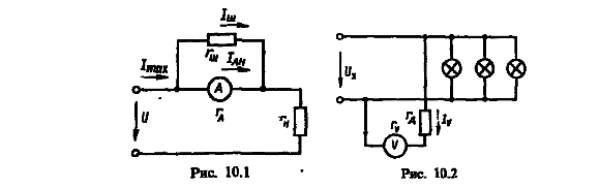
Direct inclusion of the ammeter in the circuit of the measured current is not always possible, since in some cases the measured current is many times greater than necessary for the complete deflection of the moving system of the device. In these cases, when measuring direct current, a shunt is connected in parallel with the ammeter, through which most of measured current (Fig. 10.1).
As a technician or handyman, it is always necessary to have the right measuring tools for effective work. In order to protect sensitive equipment during transport, it is beneficial to invest in special equipment pockets. Standard solutions in the retail market are usually not suitable for the requirements of professions that require expensive equipment on transport bags. They need to be clear so that each piece has its place and can be quickly captured.
Rules for connecting an ammeter
This saves time and increases productivity. Of course, batteries must also be provided, which also requires their place. Batteries drive electrons through. The size of the electronic actuator is indicated in volts on each battery. Unfortunately, there is no information about how long the battery lasts on the device.
According to Kirchhoff's first law, the maximum value of the current measured by the ammeter in the presence of a shunt
Where I max- the maximum value of the current in the circuit; I An- nominal (limiting) value of the current of the ammeter in the absence of a shunt; I sh is the current passing through the shunt. Since the ammeter and shunt are connected in parallel, the currents between the shunt and the ammeter are distributed inversely with their resistances:
Voltmeter
Large current: the battery is quickly discharged. Battery life can be calculated based on battery capacity.
Ohmmeter
Measure voltage or current correctly. Often current and voltage should be measured simultaneously. In this case, it is necessary to take into account the resistance value that the load can take. One voltmeter has a high internal resistance. The ammeter has a low internal resistance.If we measure voltage and current at the same time, we distinguish between adjacent circuits. Recall the basic laws of electrical engineering and calculate the effect of error as an example for small or large resistance for each of two circuits, consider measuring device as a resistor.
![]()
where we find the resistance of the shunt:
Where r A- internal resistance of the ammeter; n = I max /I An- coefficient showing how many times the measurement limits are expanded.
Because ![]() then the current in the circuit at a given load
then the current in the circuit at a given load
Do you know the reason for the name?
- The measured value is always subject to errors.
- The measuring device acts on the circuit itself.
To measure direct current, you must proceed as follows. The negative pole of the voltage source must be connected to the negative pole of the meter. As a result, the positive pole of the voltage source is also connected to the positive terminal of the meter.
- Set the largest measurement range for the current measurement.
- Place the counter in series.
Where I A- ammeter reading. If the scale of the ammeter is calibrated taking into account the shunt, then it is possible to determine the value of the measured current I directly from the readings of the device.
When measuring alternating currents, shunts are not used. This is because the distribution of currents between the shunt and the ammeter is determined not only by their active resistance, but also reactance device, which depends on the frequency. Therefore, to expand the measurement limits of ammeters in AC circuits, measuring current transformers are used.
Then switch the measurement range down so that the pointer is in the middle to the right display area.
- In this case, polarity does not matter.
- Read the current one.
Voltage measurement. Electrical measuring instruments designed to measure voltage are called voltmeters. Voltmeters are connected in parallel to the section (element) of the electrical circuit, on which the voltage is measured. In this case, the voltmeter must have a very large resistance compared to the resistance of the circuit element on which the voltage is measured. This is necessary to reduce the measurement error and to ensure that there is no change in the operating mode of the circuit. In fact, the greater the resistance of the voltmeter, the less current passes through it and the less energy is consumed in it, and therefore, the less influence the inclusion of the device has on the mode of operation of the circuit.
In other words: If the current resolution of the device is fully selected by selecting the appropriate measuring range, then the voltage difference during the measurement is up to 200 mV. Example. You are measuring a current of 100 µA in the 200 µA measurement range of a DMM. The turn-on range is 200 µA.
It is safe to measure currents in an electrical circuit as long as this voltage drop has no effect on the remaining functions of the measuring object. However, in an electrochemical cell, 100 mV is already a lot: remember that, for example, a potential change of -114 mV, for example, results in a tenfold increase in current at room temperature during hydrogen precipitation. Even more dramatic is the effect of the metal flow solution: here the currents change from 59 mV or even 40 mV to the current decade.
To expand the measurement limits of voltmeters in DC circuits with voltages up to 1000-4500 V, additional resistors are used, connected in series with the device (Fig. 10.2). In AC circuits with voltages above 1000 V, voltage transformers are used to expand the measurement limits.
The device and connection of the shunt
From this it can be seen that such a device is not suitable for measuring currents. short circuit between two galvanic coupling electrodes, unless it operates in the maximum possible measuring range which still allows a safe reading. In this case, to keep the measurement error within acceptable limits, the measuring range should be 2 mA. Then the mutual polarization of the measuring electrodes is only 10 mV at 100 μA, which, accordingly, reduces the falsification of the measurement result, but the accuracy of the current measurement on the device itself also decreases accordingly.
When an additional resistor is connected in series with a voltmeter, the resistance of the latter is determined from the following considerations: for example, a voltmeter with resistance r V rated for rated voltage U nom, it is necessary to measure the voltage U xmax, which is n times larger U nom. In this case, it is necessary to observe the condition under which the current passing through the voltmeter would be the same at both voltages, i.e.
If you now change to a measuring range of 20 mA, the falsification of the measurement results will remain less than 1%, but the measurement result will be only ± 10%! Therefore, electrochemical measurements require a current measurement that does not cause any potential differences between measurement points. For this purpose, a special "ammeter" with zero-ohm is proposed. But you can also switch the potentiostat like a zero ohm ammeter. Connect the contact electrode connection and the counter electrode connection.
One of the two electrodes to be measured is connected to the working electrode terminals, and the other to the reference and counter electrode terminals. The controlled potential is set to zero - that's the whole trick! Now you only need to adjust the appropriate current range. The measurement result can be read from the built-in device, or a sufficiently accurate voltage measuring device can be connected to the current output: then it displays the current with millimeter accuracy.
![]() (10.3)
(10.3)
and actually measured voltage
Where U V- voltmeter reading.
The scale of voltmeters in most cases is calibrated taking into account the additional resistance r d. In this case, the voltmeter can be made to several measurement limits, for which it is equipped with several additional resistances and the corresponding scale switch on front side device.
Polarity: In our potentiostats, the anode current is indicated by the working electrode as a positive current on the meter. The current is now measured through the voltage between the counter electrode contact on the potentiostat and ground. Note. The larger the measuring resistor, the more noise generated by this resistor. A capacitor in parallel with this measuring resistor reduces the noise, but at the same time also truncates the frequency band for recording the measured values.
This is irrelevant for DC measurements. The largest capacity you can use with it, then. The practically available value will be 6.8 pF and 5.6 pF, respectively. For DC measurements it is theoretically possible to choose arbitrarily large capacitors, in practice it will be limited by the value. For example, it reduces noise of 50 Hz, but does not require infinite adjustment time for current changes. In this example, 68 nF would be the usable capacitance.
Magnetoelectric voltmeters are used to measure voltage in direct current circuits, and electromagnetic and electrodynamic voltmeters are used in alternating current circuits. When measuring small variable voltages rectifier and electronic millivoltmeters are used, and at elevated frequencies, mainly electronic ones.
To accurately understand the meaning of the concept, we must know what amplifiers are and what electric current is. Electric current is created by movement electric charges in the material. This is a value that reflects what flows through a conductive material in a unit of time. The ampere in this frame is the unit that quantifies the intensity of the current.
Returning to the concept of an ammeter, this device measures the current that circulates in an electrical circuit. When connecting an ammeter to an electrical circuit, you can detect the number of amperes of current in circulation. The measurement consists in passing electric current through the device. Internal resistance the ammeter is very small, so there is no voltage drop during the measurement. If it is necessary to measure the current without an aperture, a special class of ammeters, known as the clamp amperometric meter, must be used, which indirectly determines the intensity of the magnetic field generated by a given current.
If a working voltage is applied to an electrical circuit, then a current of a certain value will flow through its elements. Its value is determined by the resistance value of individual sections of the circuit. To measure the current value of the current, in a certain area are used special devices, which are called .
Let's take for example. Before understanding the question of how this device works, it is important to consider the classifications.
There are several types of ammeters, which can be roughly divided into three groups: analog, digital and amperometric tweezers. The description presented in the previous paragraphs is nothing more than the basis of the old ammeters, which were analog. Like many other fields, although it was developed a long time ago, it is still used today.
Analog ammeters present the result of a measurement with a needle that is located at the appropriate point between the minimum and maximum available in the reading. In this group of instruments we find two subgroups: electromechanical and thermal ammeters.
Types of ammeters
- Magnetoelectric. Such devices are only suitable for direct current measurements. They are characterized by high sensitivity and low power.
- Electromagnetic. The instruments can be used to measure direct and alternating currents. Their disadvantage is low sensitivity and low accuracy.
- Electrodynamic. Devices of this type are highly sensitive to external magnetic fields, so their use for high-precision measurements is undesirable.
- Ferrodynamic. These devices are different increased stability to external magnetic fields and have high strength. They are widely used in the field of security, as well as in cases where high-precision measurements are required.
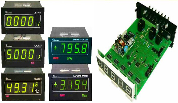
- Digital. For example, they do not have moving mechanical parts, but work on the basis of a platform with a microprocessor, which allows you to convert the amount of passing current into digital signals that are displayed on the LCD.
Fig.1 - Mechanical ammeters
Generally speaking, it can be said that electromechanical ammeters rely on the mechanical interaction that occurs between electrified conductors, between magnetic field and current or between two currents. Their design is relatively simple: they have two organs, one mobile and one fixed, and one to indicate the final value.
This type of ammeter is undoubtedly quite bulky, which results in more wear and tear on its parts, as well as a greater likelihood of measurement. On the other hand, it quickly outperforms other models and is useful for reading in fixed positions. This group includes magnetoelectric, electromagnetic, electrodynamic and ferromagnetic ammeters.
Fig.2 - Digital ammeters
Ammeter design
To understand how the ammeter works, consider its design (Fig. 3). Devices of this type are magnetoelectric devices in which a current is applied to the winding of the coil, which leads to the generation of a magnetic flux that interacts with permanent magnet. There are several modifications of measuring systems - in one case, the measuring pointer is attached to a moving coil, and in the other case, a permanent magnet is movable, which is connected to the pointer. The measuring coil is connected to a shunt, which is located inside the device or outside it, from which the current strength indicators are taken.
Thanks to the advances in technology, this type of ammeter has appeared, more versatile and practical than a similar one. Among its main benefits are reduced wear and a significant reduction in the chance of error. Instead of a panel with a needle, they have a screen where you can view the results.
This type of ammeter is also known as a clamp or hook and is very useful as it allows the intensity to be reduced instantly without interrupting or opening the circuit. Because no electrical windings, no fire hazard. It is measured in volts, like voltage.

Fig.3 - Ammeter design
The principle of operation of the ammeter
As soon as a current is applied to the measuring system of the ammeter, the value of which is determined, a magnetic field is generated in the coil of the device. It interacts with the field created by the permanent magnet, which causes the turning frame with the pointer to deviate (Fig. 4). The angle of deviation is proportional to the passing current and, with a certain calibration, the arrow will point on the measuring scale of the device to the current value of the current.
In digital ammeters, such as, the current value is determined by means of special analog-to-digital converters, which convert the current signal into a sequence of digital codes displayed on the device screen as a numerical value.
There are cases when it is necessary to measure the current, the value of which is greater than the maximum value of the measuring range. In this case, it is important to know how the ammeter shunt works. A shunt is a resistive element with a known value electrical resistance, which is connected in parallel to the ammeter. The shunt is designed for the amount of current that needs to be measured with an ammeter with a smaller operating range.
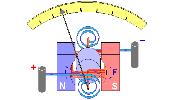
Fig. 4 - The principle of operation of the ammeter
How to connect an ammeter
In order to use measuring instruments correctly, it is important not only to know how the ammeter and voltmeter work, but also how to connect them. To measure the current that passes through the instrument or through certain part electrical circuit, the ammeter must be connected in series with this section.

Fig. 5 - Scheme of connecting an ammeter through a shunt
Practical use
Ammeters are widely used in the process of building, maintaining and repairing various electronic equipment. As one example practical application you can consider the ammeter on the charger - we will consider how this device works below. Of such a type charging device charge the batteries with current constant value, the value of which is visualized using an ammeter. During the charging process, the current strength may drop and it will be possible to determine the need for its regulation by the ammeter. The battery is considered charged if the current on the ammeter does not change for 1-2 hours.
This is just one of many examples of the practical use of measuring instruments such as ammeters.
 (1 ratings, on average: 5,00 out of 5)

