Autonics proximity sensors: inductive and capacitive. Non-contact sensors Application of inductive sensor
- These are sensors that operate without physical and mechanical contact. They operate through electric and magnetic fields, and optical sensors are also widely used. In this article, we will analyze all three types of sensors: optical, capacitive and inductive, and at the end we will do an experiment with an inductive sensor. By the way, people also call contactless sensors proximity switches, so don't be afraid if you see such a name ;-).
Optical sensor
So, a few words about optical sensors... The principle of operation of optical sensors is shown in the figure below
Barrier
Remember those scenes from movies where the main characters had to walk through optical beams without hitting any of them? If the beam touched any part of the body, an alarm was triggered.

The beam is emitted through some source. There is also a “beam receiver”, that is, the little thing that receives the beam. As soon as the beam is not on the beam receiver, a contact in it will immediately turn on or off, which will directly control the alarm or anything else at your discretion. Basically, the beam source and the beam receiver, correctly called the beam receiver “photodetector,” come in pairs.
Optical displacement sensors from SKB IS are very popular in Russia.


These types of sensors have both a light source and a photodetector. They are located directly in the housing of these sensors. Each type of sensor is a complete design and is used in a number of machines where increased processing accuracy is required, down to 1 micrometer. These are mainly machines with a system H and verbal P programmatic U board ( CNC), which work according to the program and require minimal human intervention. These non-contact sensors are built on this principle

These types of sensors are designated by the letter “T” and are called barrier. As soon as the optical beam was interrupted, the sensor was activated.
Pros:
- range can reach up to 150 meters
- high reliability and noise immunity
Minuses:
- at long sensing distances, precise adjustment of the photodetector to the optical beam is required.
Reflex
The reflex type of sensors is designated by the letter R. In these types of sensors, the emitter and receiver are located in the same housing.

The operating principle can be seen in the figure below

Light from the emitter is reflected from some light reflector (reflector) and enters the receiver. As soon as the beam is interrupted by any object, the sensor is triggered. This sensor is very convenient on conveyor lines when counting products.
Diffusion
AND last type optical sensors – diffusion - designated by the letter D. They may look different:


The principle of operation is the same as that of a reflector, but here the light is already reflected from objects. Such sensors are designed for a short response distance and are unpretentious in their operation.

Capacitive and inductive sensors
Optics are optics, but inductive and capacitive sensors are considered the most unpretentious in their operation and very reliable. This is roughly what they look like

They are very similar to each other. The principle of their operation is associated with changes in magnetic and electric field. Inductive sensors are triggered when any metal is brought close to them. They don't bite on other materials. Capacitive ones react to almost any substance.
How does an inductive sensor work?
As they say, it’s better to see once than to hear a hundred times, so let’s do a little experiment with inductive sensor.
So, our guest is an inductive sensor Russian production

We read what is written on it

Brand of VBI sensor blah blah blah blah, S – sensing distance, here it is 2 mm, U1 – version for temperate climates, IP – 67 – protection level(in short, the level of protection here is very steep), U b – voltage at which the sensor operates, here the voltage can be in the range from 10 to 30 Volts, I load – load current, this sensor can deliver a current of up to 200 milliamps to the load, I think this is decent.
On the reverse of the tag there is a connection diagram for this sensor.

Well, let's check out the sensor's performance? To do this, we attach the load. Our load will be an LED connected in series with a resistor with a nominal value of 1 kOhm. Why do we need a resistor? The moment the LED is turned on, it begins to frantically consume current and burns out. In order to prevent this, a resistor is placed in series with the LED.

We supply the brown wire of the sensor with plus from the power supply, and the blue wire with minus. I took the voltage to 15 Volts.
The moment of truth is coming... We bring it to work area sensor is a metal object, and our sensor immediately triggers, as evidenced by the LED built into the sensor, as well as our experimental LED.

The sensor does not respond to materials other than metals. A jar of rosin means nothing to him :-).

Instead of an LED, a logic circuit input can be used, that is, when the sensor is triggered, it produces a logical one signal, which can be used in digital devices.
Conclusion
In the world of electronics, these three types of sensors are increasingly used. Every year the production of these sensors is growing and growing. They are absolutely used in different areas industry. Automation and robotization would not be possible without these sensors. In this article, I analyzed only the simplest sensors that give us only an “on-off” signal, or, to put it in professional language, one bit of information. More sophisticated types of sensors can provide different parameters and can even connect directly to computers and other devices.
Buy an inductive sensor
In our radio store, inductive sensors cost 5 times more than if they were ordered from China from Aliexpress.

Here You can look at the variety of inductive sensors.
Today I contacted him.
1500 won't go away, but it won't cause the CHECK to light either. It hangs somewhere inside and doesn’t get in the way.
0110 will be removed as soon as the sensor is connected.
As for the spark, well, my damaged (but apparently intact) explosive wires killed the coil. A motor shield that is still swollen from water can also cause problems.
Maybe it’s really better to contact Vladimir (Shish)?
Vladimir has not yet responded to his letter as of today.
I reason:
To improve the spark, the distributor cover and slider were cleaned and installed. For example, to start a car, take the wires and connect to another running car. And try to start it.
From the history of the plant of this car:
It didn’t start after 2 rainy days, I checked the gas pump, it works, I bought new spark plugs and checked the spark, and I got an electric shock on my hands when I was holding the wires with my hands. I tried to start the starter and it would not start. I approached my neighbor in a jeep and he gently gave me a ride on a rope. I turned on the ignition, squeezed the clutch into 3rd gear, released the clutch and just drove without any reaction. We stopped and offered to start it for me. My starter turns and that’s it. My neighbor suggested that I unscrew the spark plugs and dry them (maybe they have flooded).
On the forum they recommended that I change the coil - I did. I checked the wires, I have 2 sets. I unscrewed the spark plugs and dried them. I checked that there was a spark on all of them and it was strong (from my understanding). While I was doing this, I met my neighbor again in a jeep - he showed that he had changed the coil, the wires were different, but it wouldn’t start (the starter turns and that’s it). He offered to give me a ride on the rope again, but he says this unhelpfully. There is a sensor in the distributor that is responsible for the timely supply of fuel for the spark - if it does not work, it is useful to carry it on a cable and start it too (I apologize if I did not describe it exactly as I remembered). I suggested cleaning the contacts in the distributor coil and the slider, check sensor. In this engine it is in the distributor. There are other engines that have it separately (crankshaft sensor).
I removed the distributor cover and the slider (there is a photo earlier in the correspondence). I cleaned it and put it back. I noticed that the slider changes its location when the car is turned on and started.
No one asked how to check the sensor - the answer was to install a new distributor or described their history - they say it is not an optical sensor.
At the same time I caught two errors:
0110 Manifold air temperature sensor (MAT) Intake air temperature sensor error - I have removed the air filter housing and disconnected the sensor
1500 A/C evaporator thermistor malfunction Air conditioning evaporator temperature sensor error - machine without air conditioning.
One may come off during installation. air filter and connecting the sensor - before this you need to disconnect the battery (as I understand).
The second is without clarity on how to clean it.
I checked everything that was possible for the plant - only the optical sensor remains to be checked. There is an opportunity to check it and what kind (to be sure, it’s him. Example: I disassembled the fuel pump and checked the motor, then replaced the motor with a new one).
He already wrote to me about the Matiz factory on a cable and explained what the consequences would be (without a factory on a cable).
Inductive proximity sensor. Appearance
IN industrial electronics inductive and other sensors are used very widely.
The article will be a review (if you want, popular science). Real instructions for the sensors and links to examples are provided.
Types of sensors
So, what exactly is a sensor? A sensor is a device that produces a specific signal when a specific event occurs. In other words, the sensor is activated under a certain condition, and an analog (proportional to the input effect) or discrete (binary, digital, i.e. two possible levels) signal appears at its output.
More precisely, we can look at Wikipedia: Sensor (sensor, from the English sensor) is a concept in control systems, a primary transducer, an element of a measuring, signaling, regulating or control device of a system that converts a controlled quantity into a signal convenient for use.
There is also a lot of other information, but I have my own, engineering-electronics-applied, vision of the issue.
There are a great variety of sensors. I will list only those types of sensors that electricians and electronics engineers have to deal with.
Inductive. Activated by the presence of metal in the trigger zone. Other names are proximity sensor, position sensor, inductive, presence sensor, inductive switch, proximity sensor or switch. The meaning is the same, and there is no need to confuse it. In English they write “proximity sensor”. In fact, this is a metal sensor.
Optical. Other names are photosensor, photoelectric sensor, optical switch. These are also used in everyday life, they are called “light sensors”
Capacitive. Triggers the presence of almost any object or substance in the field of activity.
Pressure. There is no air or oil pressure - the signal to the controller or vomits. This is if discrete. There may be a sensor with a current output, the current of which is proportional to absolute or differential pressure.
Limit switches(electrical sensor). This is a simple passive switch that trips when an object runs over or presses against it.
Sensors may also be called sensors or initiators.
That's enough for now, let's move on to the topic of the article.
The inductive sensor is discrete. The signal at its output appears when metal is present in a given zone.
The proximity sensor is based on a generator with an inductor. Hence the name. When metal appears in the electromagnetic field of the coil, this field changes dramatically, which affects the operation of the circuit.

Field induction sensor. Metal plate changes resonant frequency oscillatory circuit

Inductive npn sensor circuit. A functional diagram is shown, which shows: a generator with an oscillating circuit, a threshold device (comparator), an NPN output transistor, protective zener diodes and diodes
Most of the pictures in the article are not mine; at the end you can download the sources.
Application of inductive sensor
Inductive proximity sensors are widely used in industrial automation to determine the position of a particular part of the mechanism. The signal from the sensor output can be input to a controller, frequency converter, relay, starter, and so on. The only condition– current and voltage matching.
What's new in the VK group? SamElectric.ru ?
Subscribe and read the article further:

Operation of an inductive sensor. The flag moves to the right, and when it reaches the sensor's sensitivity zone, the sensor is triggered.
By the way, sensor manufacturers warn that it is not recommended to connect an incandescent light bulb directly to the sensor output. I have already written about the reasons - .
Characteristics of inductive sensors
How are the sensors different?
Almost everything that is said below applies not only to inductive, but also to optical and capacitive sensors.
Design, type of housing
There are two main options - cylindrical and rectangular. Other housings are used extremely rarely. Case material – metal (various alloys) or plastic.
Cylindrical sensor diameter
Main dimensions – 12 and 18 mm. Other diameters (4, 8, 22, 30 mm) are rarely used.
To secure an 18 mm sensor, you need 2 keys of 22 or 24 mm.
Switching distance (working gap)
This is the distance to metal plate, which guarantees reliable operation of the sensor. For miniature sensors this distance is from 0 to 2 mm, for sensors with a diameter of 12 and 18 mm - up to 4 and 8 mm, for large sensors - up to 20...30 mm.
Number of wires to connect
Let's get to the circuitry.
2-wire. The sensor is connected directly to the load circuit (for example, a starter coil). Just like we turn on the lights at home. Convenient for installation, but capricious in terms of load. They work poorly with both high and low load resistance.

2-wire sensor. Connection diagram
The load can be connected to any wire; for constant voltage it is important to maintain polarity. For sensors designed to operate with alternating voltage, neither the load connection nor the polarity matters. You don't have to think about how to connect them at all. The main thing is to provide current.
3-wire. The most common. There are two wires for power and one for load. I'll tell you more separately.
4- and 5-wire. This is possible if two load outputs are used (for example, PNP and NPN (transistor), or switching (relay). The fifth wire is the choice of operating mode or output state.
Types of sensor outputs by polarity
All discrete sensors can have only 3 types of outputs depending on the key (output) element:
Relay. Everything is clear here. The relay switches the required voltage or one of the power wires. This ensures complete galvanic isolation from the sensor power circuit, which is the main advantage of such a circuit. That is, regardless of the sensor supply voltage, you can turn on/off the load with any voltage. Mainly used in large-sized sensors.
Transistor PNP. This is a PNP sensor. The output is a PNP transistor, that is, the “positive” wire is switched. The load is constantly connected to “minus”.
Transistor NPN.At the output there is an NPN transistor, that is, the “negative” one is switched, or neutral wire. The load is constantly connected to the “plus”.
You can clearly understand the difference by understanding the principle of operation and switching circuits of transistors. The following rule will help: Where the emitter is connected, that wire is switched. The other wire is connected to the load permanently.
Below will be given sensor connection diagrams, which will clearly show these differences.
Types of sensors by output status (NC and NO)
Whatever the sensor, one of its main parameters is the electrical state of the output at the moment when the sensor is not activated (no impact is made on it).
The output at this moment can be turned on (power is supplied to the load) or turned off. Accordingly, they say - a normally closed (normally closed, NC) contact or a normally open (NO) contact. In foreign equipment, respectively – NC and NO.
That is, the main thing you need to know about transistor outputs of sensors is that there can be 4 types of them, depending on the polarity of the output transistor and the initial state of the output:
- PNP NO
- PNP NC
- NPN NO
- NPN NC
Positive and negative logic of work
This concept refers rather to actuators that are connected to sensors (controllers, relays).
NEGATIVE or POSITIVE logic refers to the voltage level that activates the input.
NEGATIVE logic: the controller input is activated (logic “1”) when connected to GROUND. Controller S/S terminal ( common wire for digital inputs) must be connected to +24 VDC. Negative logic used for NPN type sensors.
POSITIVE logic: the input is activated when connected to +24 VDC. The S/S controller terminal must be connected to GROUND. Use positive logic for PNP type sensors. Positive logic is used most often.
There are options for various devices and connecting sensors to them, ask in the comments and we’ll think about it together.
Continuation of the article -. In the second part, real diagrams are given and discussed practical use various types sensors with transistor output.
In industrial automation, position sensors are the main source of information for determining the physical position of mechanical components of equipment.
Once upon a time, limit switches were used as such sensors. Their disadvantages are obvious:
- not high reliability;
- limited work resource;
- low accuracy;
- low performance;
- mechanical rattle.
All of these disadvantages are compounded by the fact that position sensors are typically physically located in harsh environments. This:
- vibrations;
- dust;
- high humidity;
- wide range of operating temperatures.
Limit switches have been replaced by non-contact optical position sensors. They consist of an optical emitter and a photodetector. The light flux from the emitter hits the photodetector, which causes a certain state of the sensor. The presence of an opaque object in the path of the light ray leads to a change luminous flux on the photodetector, and therefore to a different state of the sensor.
One of the most common optical position sensors is the KTIR0411S manufactured by Kingbright. Him:
- low price;
- high specifications;
- good design.
In my developments, I prefer to use these sensors.
Design and principle of operation of the KTIR0411S sensor.
The KTIR0411S sensor is made of plastic cast case, which contains:
- optical emitter – gallium arsenide LED;
- optical receiver – silicon phototransistor.
In the sensor housing, between the emitter and the receiver, there is a gap approximately 3 mm wide. The presence or absence of a light-proof object in this gap is indicated by the sensor.


Therefore, sensors of this type have other names:
- slot optocoupler;
- slot optical sensor;
- photointerrupter;
- photo interrupter;
- photointerruptor.
Dimensions and pin assignments of the KTIR0411S sensor.
This information and subsequent technical specifications are taken from the manufacturer's website.
Connection diagram for the KTIR0411S slot optocoupler.
For the photointerrupter to function, a current of 20-30 mA must be supplied through the LED (pins + and E), and the state of the phototransistor output (pins + and D) must be monitored. The closed state of the photodetector transistor means that the light flow is not interrupted. The connection diagram for the KTIR0411S sensor may look like this.

Resistor R1 limits the LED current to 25 mA, and resistor R2 limits the output transistor collector current to 5 mA. A voltage of +5 V at the output of the circuit means that a light-proof object is in the photointerrupter slot.
Here's an example mechanical design take-up drum positioning unit.

A model disk with cut out windows is attached to the drum shaft. Or rather, it is attached to the shaft on one side, and the drum itself is attached to the motor shaft on the other side. Those. The stepper motor, drum and disk have a common shaft.
The sample disk is made with high precision using a laser cutting machine. The position sensor is placed so that the edge of the disk fits into the photointerrupter slot. When the drum is turned, the disc interrupts the flow of the light beam at the position where the windows end. Those. The machine controller determines the position of the drum and stops it in the places where the windows begin. Very simple and reliable design.
Extremely valid parameters slot optical sensor KTIR0411S.
| Parameter | Designation | Meaning |
| Input LED | ||
| LED forward current | I F | 50 mA |
| LED Reverse Voltage | V R | 6 V |
| LED power dissipation | P D | 75 mW |
| Peak forward current (pulse duration< 100 мкс, скважность < 1%) | I FP | 1 A |
| Output transistor | ||
| Collector-emitter forward voltage | V CEO | 35 V |
| Collector-Emitter Reverse Voltage | V ECO | 6 V |
| Collector current | I C | 20 mA |
| Output transistor power dissipation | P C | 75 mW |
| Operating temperature range | T OPR | -25...+85 C° |
- The LED cannot be supplied with a current greater than 50 mA;
- to the output transistor - voltage more than 35 V and current more than 20 mA.
Operating parameters of the KTIR0411S optical position sensor.
| Parameter | Designation | Meaning |
| Input LED | ||
| Forward voltage to LED (current 20 mA) | V F | 1.2 - 1.5 V |
| LED reverse current (voltage 5V) | I R | 10 µA |
| Output transistor | ||
| Collector-emitter saturation voltage (collector current 1 mA, LED current 40 mA) | VCE(sat) | 0.4 V |
| Closed transistor current (collector-emitter voltage 20 V) | I CEO | 100 nA |
| Transfer characteristic | ||
| Current transfer coefficient (collector-emitter voltage 5 V, LED current 20 mA) | CTR | 38 % |
| Positive edge response time (2V collector-emitter voltage, 2mA collector current) | t r | 5 - 25 µs |
| Falling Edge Response Time (2V Collector-Emitter Voltage, 2mA Collector Current) | t f | 4 - 20 µs |
The main of these parameters.
Direct voltage on the LED - taken into account when calculating the limiting resistor. The current through the sensor LED is calculated by the formula
I = (U – V F) / R1
In the previous scheme, I = (12 – 1.2) / 430 = 0.025 A.
The CTR (current transfer ratio) parameter affects the selection of current through the sensor LED.
Maximum output current of the sensor Iout max = I LED * CTR / 100.
For the above circuit, the maximum output current is 0.025 * 0.38 = 9.5 mA. Those. resistor R2 should limit the current of the output transistor to no more than 9.5 mA. Otherwise, the current will be limited by the sensor itself, but the voltage at its output will be raised.
Slot optocouplers KTIR0411S are used in almost all ROST products from the section. Another design example.

The sensors showed their best performance the best side. Here is a film of the machine in action. All mechanisms are positioned using slotted optical position sensors KTIR0411S.
![]() Non-contact sensors approximations can be found in medical devices, as part of automated industrial lines, in household appliances. One of the world's leading manufacturers of automation products, Autonics, offers non-contact proximity sensors in the (inductive) and (capacitive) series.
Non-contact sensors approximations can be found in medical devices, as part of automated industrial lines, in household appliances. One of the world's leading manufacturers of automation products, Autonics, offers non-contact proximity sensors in the (inductive) and (capacitive) series.
What do the inductosyn of a milling machine, a smartphone touch screen, a car door sensor, and an automatic light have in common? The answer is that all of the above applications use proximity sensors.
Proximity sensors are elements that allow you to detect the presence, approach or removal of various objects. This is a fairly wide class of devices (Figure 1).

Based on the type of interaction with an object, proximity sensors are divided into contact and non-contact.
Vivid examples contact sensors are limit switches (for example, door closing sensors in cars).
Contact sensors can not only perform the function of switching on and off, but also determine the position of an object, for example, resistive fuel level sensors. For them, the output is an analog signal - a resistance value proportional to the liquid level.
The advantages of contact sensors are their ease of design and use. Among their disadvantages, one can note the presence of mechanical moving parts and the inability, in most cases, to create high level dust and moisture resistance, which leads to a reduction in service life. Much longer service life and maximum protection against negative impact external environment have contactless sensors.
Proximity sensors are divided into two groups: position sensors and switches. The main function of proximity switches is to relay switch the output state when an object is detected. In position sensors, the output signal is generated depending on the distance to the object.
Each group contains sensors with various technologies detection: inductive, capacitive and photoelectric.
Let's consider contactless inductive and capacitive switches manufactured by Autonics.
Design and principle of operation of inductive and capacitive proximity sensors
Capacitive and inductive sensors are capable of detecting the presence of an object without direct contact with it. In this case, inductive switches are sensitive only to metal objects, and capacitive ones are capable of detecting any objects whose dielectric constant is different from air (for example, water, wood, metal, plastic, and so on). Let's consider the operating principle of each sensor separately.
The main element of an inductive sensor is an inductor (Figure 2). It is connected to the generator. Variable electrical voltage causes an alternating magnetic field at its terminals. The field lines will be perpendicular to the direction of the current in the turns of the coil.
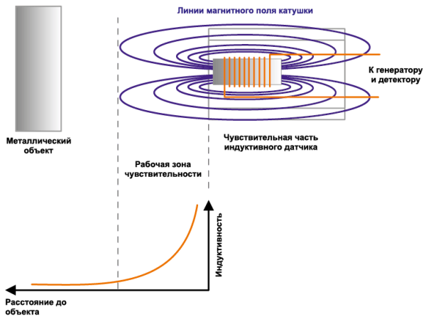
If there are no metal objects near the coil, the lines magnetic field are closed through the air. And the amplitude of electrical vibrations will be maximum.
If you bring a metal object closer to the coil, then everything most of lines of force will begin to close through it. The inductance of the coil will begin to increase. This process is similar to the process of inserting a core. In this case, an increase in inductance will lead to a decrease in the amplitude and/or frequency of oscillations.
If such a system is equipped with a detector, then by changing the signal amplitude one can judge the presence of a metal object, its approach or distance.
The operation of a capacitive sensor, as the name suggests, is based on the use of capacitive couplings. The sensor itself, in fact, is one of the plates of a spatial capacitor. The second covering is the earth. The dielectric is predominantly air. Since the dielectric constant of air is small (ε = 1), the capacitance of such a capacitor is small. If an object with a higher ε value begins to approach the sensor, then the total capacitance will begin to increase (Figure 3).

Thus, by the size of the capacity one can judge the presence of an object, its approach or distance. In this case, the material of the object can be almost anything, only its meaning is important dielectric constant.
Typically, measurements are made using circuits that convert capacitance into frequency or amplitude of oscillations, which are measured using a detector. As a result, as in the case of an inductive sensor, it is necessary to have two mandatory elements: generator and detector (Figure 4).

Capacitive and inductive switches have a relay type output signal - “on” or “off” (Figure 5). For this reason, the sensor circuit has a switching element - a trigger, which, to prevent false positives equipped with hysteresis.

Main characteristics and features of proximity sensors
Sensitivity zone or active zone (Sensing Distance), mm. As shown above, the range of proximity sensors is limited. A significant change in the measured capacitance and inductance is observed near the sensitive element of the sensor (Figures 2, 3).
The sensor begins to “feel” an object only at fairly close distances, comparable to the size of the sensor itself. This zone of sensitivity is called the active zone. In the case of inductive sensors, it determines the area highest density magnetic field lines.
Sensing distance, mm. After an object enters the active zone, the sensor does not switch immediately, but when a certain threshold value is reached, which is set by an internal trigger with hysteresis.
Hysteresis is necessary to eliminate false alarms. In this case, the sensor is turned on and off at different levels of oscillations.
Working gap (Setting Distance), mm – the distance at which a given object is guaranteed to be detected.
The latter definition used the term "specified object". Additional clarification is required. The fact is that all of the listed characteristics are not strictly defined. Their value is influenced by a number of factors: the material and size of the object, temperature drift, technological parameters of the sensor itself. For this reason, all characteristics given are measured using a specific object at normal temperature (usually 20 or 25°C).
The influence of the material and size of the detection object on the parameters of inductive sensors. As shown above, an approaching metal object acts as a core for the sensing coil. Obviously, the material and shape of the core have a significant impact on the inductance value.
For this reason, all ratings refer to a specific object, which is always specified in the documentation for the sensor. Usually this is an iron square plate with specified dimensions.
If it is intended to use another material, then it is necessary to use a reduction correction factor (Table 1).
Table 1. Examples of reduction coefficients of inductive sensors
The influence of the material and size of the detection object on the parameters of capacitive sensors. The capacitance of the resulting capacitor also depends on the shape and material of the object. The maximum sensitivity of the sensor is observed for materials with high dielectric constant (Table 2).
Table 2. Dielectric constant values for various materials
It is important to understand that when setting up and installing the sensor, you should take into account the possibility of the object being monitored becoming wet or oily. For example, for water ε = 80, so even the thinnest film of water will lead to a significant change in capacity. Any user of a laptop with a touchpad can verify this. If the touchpad gets wet, the laptop will lose control until the sensor surface is completely dry. The same picture is observed in the case of industrial capacitive sensors.
The size of the object also matters. The larger the object, the greater the capacity.
Temperature drift of proximity sensor parameters. This dependence characterizes the change in sensor characteristics (dimensions of the active zone and working gap) with temperature changes.
Initial accuracy, %. In addition to the nominal values, the documentation for the sensor always indicates the initial accuracy - the value for a given temperature and humidity. This spread is due to technological features sensor production.
Response Frequency, Hz, characterizes the switching frequency of the sensor.
Sensors powered by constant voltage have the highest response frequency. In this case, there is a dependence of the frequency on the size of the active surface of the sensor and the distance to the object (Table 3).
Table 3. Influence of the size of the active surface and the distance to the object on the response frequency of a 2-wire cylindrical sensor direct current 24 V
| Diameter, mm | Distance, mm | frequency Hz |
| M08 | 1,5 | 1500 |
| 2 | 1000 | |
| M12 | 2 | 1500 |
| 4 | 500 | |
| M18 | 5 | 500 |
| 8 | 350 | |
| M30 | 10 | 400 |
| 15 | 200 |
Sensors powered by AC power have a lower switching frequency. However, there is no dependence on the size of the active surface of the sensor and the distance to the object (Table 4).
Table 4. Influence of the size of the active surface and the distance to the object on the response frequency of a 2-wire cylindrical sensor alternating current 100…240 V
| Diameter, mm | Distance, mm | frequency Hz |
| M12 | 2 | 20 |
| 4 | 20 | |
| M18 | 5 | 20 |
| 8 | 20 | |
| M30 | 10 | 20 |
| 15 | 20 |
Another feature that is worth remembering when using contactless sensors is the possibility of mutual influence of neighboring sensors (Figure 6). When installing sensors, it is not allowed to place them too close at distances smaller than those specified in the documentation. This applies to both counter and parallel installations.

The type of output stage is one of the most important characteristics proximity sensors. Sensors can be two- and three-wire with normally closed and normally open contacts (Figure 7).

Two-wire Autonics sensors Available for operation with direct and alternating voltage. The load can be connected both before and after the sensor. In this case, it is important that the value of the load resistance ensures the flow of the sensor supply current. If the load resistance is too high, it is necessary to bypass it with an additional resistor.
Autonics three-wire sensors are designed to operate in DC circuits and have two versions with NPN and PNP output transistor (Figure 7). If constant contact of the load with the common bus is required, a sensor with a PNP output should be used. If the load requires connection to the power bus, a sensor with an NPN output is used.
Output current, mA – current that the output stage of the sensor can provide. Important parameter, if the sensor directly controls a powerful consumer. If its power is not enough, you should use a more powerful additional foreign key.
The intrinsic voltage drop, V, characterizes the drop across the sensor in the closed state.
Internal current consumption, mA, is measured for the case of open output contacts, that is, when no current flows through the load.
Performance characteristics. When using sensors in harsh environments industrial production You should remember such parameters as insulation resistance, electrical strength, resistance to vibration and shock loads, dust and moisture resistance rating, operating humidity temperature range.
Autonics produces a huge number of contactless switches. Let's look at two popular families: inductive PRDCM sensors and capacitive CR sensors.
Overview of PRDCM inductive sensors
PRDCM is a series of inductive cylindrical switches with an increased sensitivity zone and a status LED (Figure 8).
|
|
|


The sensors are available in two-wire (Table 6) and three-wire (Table 5) versions. Core members of the family reaches 25 mm, and the working gap is 17.5 mm. The response frequency range is up to 600 Hz.
Table 5. Main characteristics of three-wire sensors of the PRDCM family
| Parameter | Name | |||||
| PRDCM12-4DN, PRDCM12-4DP, PRDCM12-4DN2, PRDCM12-4DP2, PRDCML12-4DN, PRDCML12-4DP, PRDCML12-4DN2, PRDCML12-4DP2 | PRDCM12-8DN, PRDCM12-8DP, PRDCM12-8DN2, PRDCM12-8DP2, PRDCML12-8DN, PRDCML12-8DP, PRDCML12-8DN2, PRDCML12-8DP2 | PRDCM18-7DN, PRDCM18-7DP, PRDCM18-7DN2, PRDCM18-7DP2, PRDCML18-7DN, PRDCML18-7DP, PRDCML18-7DN2, PRDCML18-7DP2 | PRDCM18-14DN, PRDCM18-14DP, PRDCM18-14DN2, PRDCM18-14DP2, PRDCML18-14DN, PRDCML18-14DP, PRDCML18-14DN2, PRDCML18-14DP2 | PRDCM30-15DN, PRDCM30-15DP, PRDCM30-15DN2, PRDCM30-15DP2, PRDCML30-15DN, PRDCML30-15DP, PRDCML30-15DN2, PRDCML30-15DP2 | PRDCM30-25DN, PRDCM30-25DP, PRDCM30-25DN2, PRDCM30-25DP2, PRDCML30-25DN, PRDCML30-25DP, PRDCML30-2SDN2, PRDCML30-25DP2 | |
| Sensitivity zone, mm | 4 | 8 | 7 | 14 | 15 | 25 |
| Hysteresis | Max. 10% of sensing distance | |||||
| 12x12x1 | 25x25x1 | 20x20x1 | 40x40x1 | 45x45x1 | 75x75x1 | |
| Working gap, mm | 0…2,8 | 0…5,6 | 0…4,9 | 0…9,8 | 0…10,5 | 0…17,5 |
| Nom supply voltage, V | 12/24 | |||||
| 0…30 | ||||||
| Current consumption, mA | Max. 10 | |||||
| Operating frequency*, Hz | 500 | 400 | 300 | 200 | 100 | 100 |
| Max. 1.5 | ||||||
| Temperature drift | Max. ±10% of sensing distance at temperature environment 20°С | |||||
| Rated current, mA | Max. 200 | |||||
| Insulation resistance | Min. 50 MΩ (500 VDC) | |||||
| 1500 V, 50/60 Hz for 1 minute | ||||||
| Vibration resistance | ||||||
| Indicator | ||||||
| Operating temperature, °C | -25…70 | |||||
| Storage temperature, °C | -30…80 | |||||
| Humidity, % | 35…95 | |||||
| Built-in protection | ||||||
| Degree of protection (IP) | IP67 (IEC standard) | |||||
| Material | ||||||
| Weight, g | PRDCM: 26 | PRDCM: 48 | PRDCM: 142 | |||
| PRDCML: 34 | PRDCML: 66 | PRDCML: 182 | ||||
Table 6. Main characteristics of two-wire sensors of the PRDCM family
| Parameter | Name | Name | ||||||
| PRDCMT08-2DO, PRDCMT08-2DC, PRDCMT08-2DO-I, PRDCMT08-2DC-I | PRDCMT08-4DO, PRDCMT08-4DC, PRDCMT08-4DO-I, PRDCMT08-4DC-I | PRDCMT12-4DO, PRDCMT12-4DC, PRDCMT12-4DO-I, PRDCMT12-4DC-I, PRDCMLT12-4DO, PRDCMLT12-4DC, PRDCMLT12-4DO-I, PRDCMLT12-4DC-I |
PRDCMT18-7DO, PRDCMT18-7DC, PRDCMT18-7DO-I, PRDCMT18-7DC-I, PRDCMLT18-7DO, PRDCMLT18-7DC, PRDCMLT18-7DO-I, PRDCMLT18-7DC-I |
PRDCMT18-7DO, PRDCMT18-7DC, PRDCMT18-7DO-I, PRDCMT18-7DC-I, PRDCMLT18-7DO, PRDCMLT18-7DC, PRDCMLT18-7DO-I, PRDCMLT18-7DC-I |
PRDCMT18-14DO, PRDCMT18-14DC, PRDCMT18-14DO-I, PRDCMT18-14DC-I, PRDCMLT18-14DO, PRDCMLT18-14DC, PRDCMLT18-14DO-I, PRDCMLT18-14DC-I |
PRDCMT30-15DO, PRDCMT30-15DC, PRDCMT30-15DO-I, PRDCMT30-15DC-I, PRDCMLT30-15DO, PRDCMLT30-15DC, PRDCMLT30-15DO-I, PRDCMLT30-15DC-I |
PRDCMT30-25DO, PRDCMT30-25DC, PRDCMT30-25DO-I, PRDCMT30-25DC-I, PRDCMLT30-25DO, PRDCMLT30-25DC, PRDCMLT30-25DO-I, PRDCMLT30-25DC-I |
|
| Sensitivity zone, mm | 2 | 4 | 8 | 7 | 14 | 15 | 25 | |
| Hysteresis | Max, 10% of sensing distance | |||||||
| Standard object to be detected (iron), mm | 8x8x1 | 12x12x1 | 25x25x1 | 20x20x1 | 40x40x1 | 45x45x1 | 75x75x1 | |
| Working gap, mm | 0…1,4 | 0…2,8 | 0…5,6 | 0…5,6 | 0…9,8 | 0…10,5 | 0…17,5 | |
| Nom supply voltage, V | 12/24 | 12/24 | ||||||
| Limit supply voltage, V | 10…30 | 10…30 | ||||||
| Current consumption, mA | Max. 0.6 | Max. 0.6 | ||||||
| Operating frequency*, Hz | 600 | 500 | 500 | 400 | 250 | 200 | 100 | |
| Voltage drop across the sensor, V | Max. 3.5 | Max. 3.5 | ||||||
| Temperature drift | Max. ±10% of sensing distance at 20°C ambient temperature | |||||||
| Rated current, mA | 2…100 | 2…100 | ||||||
| Insulation resistance | Min. 50 MΩ (=500 V) | Min. 50 MΩ (=500 V) | ||||||
| Dielectric strength | ~1500 V, 50/60 Hz for 1 minute | |||||||
| Vibration resistance | Amplitude 1 mm at a frequency of 10...55 Hz in each of the directions X, Y, Z for 2 hours | Amplitude 1 mm at a frequency of 10...55 Hz in each of the directions X, Y, Z for 2 hours | 500 m/s2 (approx. 50g) X, Y, Z directions 3 times | 500 m/s2 (approx. 50g) X, Y, Z directions 3 times | ||||
| Indicator | Operation indicator (red LED) | Operation indicator (red LED) | ||||||
| Operating temperature, °C | -25…70 | -25…70 | ||||||
| Storage temperature, °C | -30…80 | -30…80 | ||||||
| Humidity, % | 35…95% | 35…95% | ||||||
| Built-in protection | From overvoltage, reverse polarity, overcurrent | From overvoltage, reverse polarity, overcurrent | ||||||
| Material | Body/nut: nickel-plated brass, washer: nickel-plated iron, reading surface: heat-resistant acrylonitrile butadiene styrene | Body/nut: nickel-plated brass, washer: nickel-plated iron, reading surface: heat-resistant acrylonitrile butadiene styrene | ||||||
| Degree of protection (IP) | IP67 (IEC standard) | IP67 (IEC standard) | ||||||
| Weight of standard version, g | – | PRDCMT: 26 | PRDCMT: 48 | PRDCMT: 142 | ||||
| PRDCMLT: 36 | PRDCMLT: 66 | PRDCMLT: 182 | ||||||
| Weight of improved version**, g | 15,5 | 15 | 23,5 | 22 | 46,5 | 42,5 | 160 | 165 |
* – Trigger frequency is an average value: standard object with twice the width at 1/2 the nominal distance
** – The weight of the updated unit applies only to PRDCMT
Features of this series are the response distance, increased up to 2.5 times compared to the previous generation, and the presence of a connector on the body, which is convenient to use and reduces time and material costs for installation.
The output stage has six versions: two-wire normally closed and normally open, three-wire NPN normally closed and normally open, three-wire PNP normally closed and normally open. Supply voltage range for all sensors: 10…30 V.
The load characteristics of three-wire representatives are slightly higher: current - up to 200 mA, intrinsic voltage drop - up to 1.5 V. For two-wire ones - 100 mA and 3.5 V, respectively. However, three-wire ones also have a higher self-consumption - up to 10 mA (versus only 0.6 mA for two-wire ones).
All sensors in the series have excellent insulating properties (up to 1500 V) and a high insulation resistance of 50 MOhm.
The status of the sensor can be determined by the LED: if it lights up, then current flows to the load.
The sensors are resistant to high vibrations and shock loads. The degree of protection (IP) is 67. All this makes them excellent choice for domestic and industrial applications such as:
- end sensors of coordinate tables in machine tools;
- tool carousel position detectors for CNC milling machines;
- door opening sensors;
- proximity sensors in automatic robotic welding installations;
- proximity sensors in automatic assembly systems;
- defect detectors (for example, in canned food production lines);
- position detectors for carousels for automatic filling of dairy products and so on.
Order code PRDCM sensors is an eight-position designation (Table 7).
Table 7. Naming of sensors of the PRDCM family
| P | R | D | CMT | 18 | -7 | DN | -I | ||
| Sensor type | Case shape | Peculiarities | Connection type | Sensor head diameter, mm | Sensitivity zone, mm | Output type | Cable type | ||
| P – inductive | R – cylinder | D – with increased sensing distance | CMT | 2-wire, standard, connector | 12 | DN | NPN, 3-wire, normally open | I – IEC standard | |
| CMLT | 2-wire, extended connector | 18 | DN2 | NPN, 3-wire, normally closed | |||||
| C.M. | 3-wire, standard, connector | 30 | D.P. | PNP, 3-wire, normally open | |||||
| CML | 3-wire, extended connector | DP2 | PNP, 3-wire, normally closed | ||||||
| DO | 2-wire, normally open | ||||||||
| DC | 2-wire, normally closed | ||||||||
Overview of capacitive CR sensors
CR is a series of capacitive cylindrical sensors from Autonics (Figure 9).
Sensors are available in two sizes - with sensitivity zones of 8 and 15 mm, respectively.
Two-wire normally open versions CRxx-xAO and two-wire normally closed versions CRxx-xAC operate with an alternating output voltage of 110...240 V and a current of 5...200 mA. Operating frequency – 20 Hz.
Three-wire versions are designed to operate in DC voltage circuits of 10...30 V with output currents up to 200 mA. Their response frequency reaches 50 Hz (Table 8).
Table 8. Main characteristics of three-wire sensors of the CR family
| Parameter | Name | |||
| , | 85…264 | |||
| Current consumption, mA | Max. 15 | Max. 2.2 | ||
| Operating frequency *, Hz | 50 | 20 | ||
| Temperature drift | Max. ±10% of the sensing distance at an ambient temperature of 20°C | |||
| Rated current, mA | Max. 200 | |||
| Insulation resistance | Min. 50 MΩ (500 VDC) | |||
| Dielectric strength | ~1500 V, 50/60 Hz for 1 minute | |||
| Vibration resistance | amplitude 1 mm at a frequency of 10...55 Hz in each of the directions X, Y, Z for 2 hours | 500 m/s2 (approx. 50g) X, Y, Z directions 3 times | ||
| Indicator | Operation indicator (red LED) | |||
| Operating temperature, °C | -25…70 | |||
| Storage temperature, °C | -30…80 | |||
| Humidity, % | 35…95 | |||
| Built-in protection | against overvoltage, reverse polarity | from overvoltage | ||
| Degree of protection (IP) | IP66 | IP65 | IP66 | IP65 |
| Weight, g | 76 | 206 | 70 | 200 |
* – Trigger frequency is an average value: a standard object with twice the width at 1/2 the nominal distance.
The sensor status can be determined by the LED. If it lights up, current flows to the load.
The order code for CR series sensors includes 5 positions: sensor type, shape, head diameter, sensitivity zone code, output stage type code (Table 9).
Table 9. Naming of CR family sensors
| C | R | 30 | -15 | DN | |
| Sensor type | Case shape | Sensor head diameter, mm | Sensitivity zone, mm | Output type | |
| C – capacitive | R – cylinder | 18 | 8 | DN | 3-wire, NPN, normally open, 24 V DC supply |
| 30 | 15 | DN2 | |||
| D.P. | 3-wire, PNP, normally open, 24 V DC supply | ||||
| DP2 | 3-wire, NPN, normally closed, power supply 24 V DC | ||||
| A.O. | 2-wire, normally open, power supply 110…240 V AC | ||||
| AC | 2-wire, normally closed, power supply 110…240 V AC | ||||
It is worth noting the high degree of protection: IP66 for CR18, IP66 for CR30. The insulation properties are also excellent. Since capacitive sensors are capable of detecting more than just metal objects, the CR series has an even wider range of applications than inductive sensors. Scope of their application:
- limit switches of machine tools;
- detectors for automatic bottling lines for milk, beer, etc.;
- liquid level sensors;
- defect detection detectors in textile production.
Conclusion
The Autonics PRDCM series of inductive sensors are designed to detect metal objects at distances up to 25 mm. There are six possible output stage configurations for this series of sensors: two-wire normally closed and normally open, three-wire NPN normally closed and normally open, and three-wire PNP normally closed and normally open.
The Autonics CR series of capacitive sensors is designed to detect various objects (including wood, metal and plastic) at distances up to 15 mm. The sensors are available with normally closed and normally open contacts for operation in circuits AC voltage 110…240 V (suffixes AO and AC) and DC voltage 10…30 V (suffixes DN and DP).
 (1 ratings, on average: 5,00 out of 5)