Typical power supply diagram for a country house. Power supply of a private house: single-line diagram. Electrical supply diagram for a private house
WITH electrical installation work in the private sector in our country it is more bad than good. For most would-be electricians, protecting people from electric shock and property from fire, unfortunately, means nothing. At the same time, one gets the impression that ordinary users skipped physics classes at school and do not understand at all what it is electricity. But they believe very well in marketing tricks and happily attack “branded” automation, rejecting any other.
I propose to understand step by step all the issues of private power supply country house using the example of single-phase input. This guide can also be applied to apartment use. I’ll note right away that my specific solution to certain nodes is optimal balance between functionality and price, but without compromising safety!
I hope there is no need to retell the full course of physics and explain what alternating electric current is. We will also omit the moments of how this electric current appeared at the power plant and entered the power line through a step-up transformer. I'll just note that important nuance that the entire power supply system in Russia is three-phase. One phase voltage 220 volts in your outlet is only phase voltage on one of the three phases. A line voltage will be 380 volts. This circumstance should be taken into account in view of such a phenomenon as “phase imbalance,” which, nevertheless, is relevant only with old wiring that is not designed for modern loads.
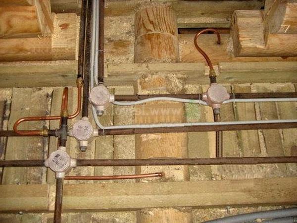
2. So, a step-down transformer in SNT. A high voltage of 10 kV comes through three wires. Then 4 wires (3 phase and one neutral conductor) diverge along the SNT. In the photo you see a modern transformer and taps in the form of SIP wires. At the moment, the air lines in our SNT are undergoing modernization.
3. When single-phase input Two conductors are connected to each consumer: phase and neutral. In the photo you can see the old ones aluminum wires on the support closest to the house. The outlet to the house has already been made using SIP wire. Particular attention to the fact that all supports overhead line must have re-grounding of the neutral conductor (top right photo). This is necessary in order to eliminate emergency situations, such as “zero break”. In this case it follows with special attention treat your own grounding in the absence of repeated grounding on intermediate supports, otherwise emergency situation your own grounding may be the only one for the entire village.
4. Get to the point. The last section of the overhead line from the nearest pole to the building is stretched with SIP wire, in our case 2x16. Stands for self-supporting insulated wire, it is aluminum with a cross-section of 16 mm². For ease of installation and laying in the place of anchor fastening, using special clamps (the SIP wire implies installation of the line under voltage, on special clamps the nut is not under tension, and also has a shear thread that guarantees the required tightening force) goes into a VVG with a cross-section of at least 10 mm² . It is in this form that the two wires enter the input panel. In the panel we have an input two-pole circuit breaker and a surge suppressor (required at the final support when air entry), which will protect the network when lightning strikes the phase conductor of the overhead line. It is connected in front of the machine to the phase conductor. Here in the panel the grounding is connected strictly BEFORE the input circuit breaker. We are looking at the scheme grounding TN-C-S, since the TT system is still created for mobile buildings, and not permanent structures, and it has its own characteristics regarding safety requirements. Disadvantages TN-C-S systems at correct installation No. Even if we go deeper into this topic, if you make a TT, then this will only be your end section, while the entire overhead line from the transformer will be TN-C.
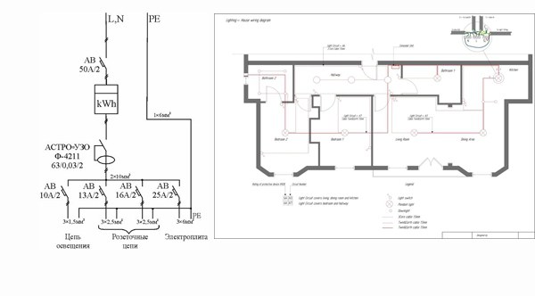
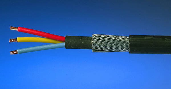
5. Mandatory grounding. Three corners with a wall of 50 mm (steel thickness 5 mm), 2 meters long, are driven into the ground with a sledgehammer and welded together in the shape of a triangle. A steel strip 40 mm wide goes to the wall of the house. The last meter to the shield is done using a copper conductor with a cross-section of at least 16 mm². It is strictly forbidden to underestimate the cross-section; in the event of any accident on the line, your grounding may become the only one for the entire line/street/block. The switching in the panel is as follows. The combined PEN (Protected Earth + Neutral) conductor from the overhead line is divided into two busbars into N and PE. After this, the input circuit breaker is switched, next to it is the surge suppressor. From the machine the power line goes to electric meter. A three-wire cable goes directly into the house copper wire with a cross section of each core of 6 mm². The phase and neutral conductors come from the meter, grounding from the corresponding bus.
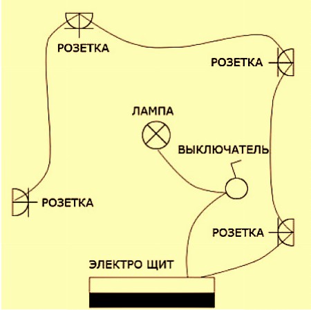
6. Let's move on to internal wiring Houses. I repeat that when designing electrical network the principle of reasonable sufficiency was used. Of course, it was possible to make 2 times more sockets and increase the number of power lines by the same amount, but I believe that this is completely unnecessary. Explanations for the diagram: red squares - distribution boxes, yellow circles - lamps. Blue indicates wiring in the screed, red - in the walls. Used everywhere in the house LED lightening(the total consumption of all lamps turned on at the same time does not reach 300 watts). The lighting is powered from the power line to a specific room, I don’t see any practical need for separation, and besides, it significantly increases the volume installation work. The diagram shows all existing consumers in the house. If you have questions, ask.
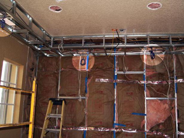
7. So, let's get started. This is a temporary electrician for the period construction work. Let's move on to laying power lines. There are 10 of them in total. Some of them will go along the walls, some in the floor in the corrugation.
8. Let's start with the floor power lines. We use an NYM cable with a cross section of 3x2.5 mm² in corrugation (the gray corrugation does not burn at all, the black one does not support combustion and has ultraviolet protection - in the screed it is not particularly important what to use, it is not so easy to find a durable gray one, but I would trample the soft one while the work was underway preparatory work). A frequently asked question - why not VVG? From point of view performance characteristics They are completely identical, but NYM has the advantage of triple insulation, while it also has the disadvantage of a non-UV resistant shell. Therefore for open wiring VVG is preferable. In other respects, NYM is more convenient, including because of its round shape(round VVG also exists, but it is extremely difficult to find it in stock). A round NYM can be easily pulled into a corrugation with a diameter of 16 mm, which is extremely convenient. As a keepsake, it’s worth documenting the routes for laying lines along the floor, although nowhere except for door thresholds is there even a theoretical probability that you will need to drive something into concrete screed floor.
9. Corner kitchen area. Aerated concrete is simply an excellent material for processing - you can even scratch the walls with an ordinary screwdriver. So, we drill holes for mounting and distribution boxes. The wire in walls made of NON-COMBUMBABLE bases is laid in the form in which it is. No corrugations are required. All attention to the tracks. Power lines are laid only at right angles. The main line runs along the floor at a height of 20-30 cm, then rises strictly VERTICALLY to sockets and switches. Diagonal laying is prohibited and is dangerous with the risk of getting into the wire, for example, when driving a nail into a wall (and so you know for sure that you cannot drive nails exactly under sockets and above switches). The cable is attached to the wall using plastic round brackets (two holes are drilled and the bracket is inserted).
10. Floor screed flooded. The question at what stage to lay the cable along the wall is purely a matter of your personal preference. Someone first plaster the walls, then make a groove, lay a cable and seal the groove back. I prefer to do the wiring before plastering the walls. This method may seem inconvenient because... extra attention will be required during plastering works to the points with mounting boxes (you need to plug them with something and then pick them out). Pay attention to the left corner - all switching on the pass-through lines of sockets is made not in socket boxes, but in separate distribution boxes.
11. I will repeat with the type of wires. NYM is an ideal and universal cable. The cross section is selected in accordance with the load. Usually a 3x2.5 mm² cable is used. For powerful consumers, such as electric hob A wire with a core cross-section of 4 mm² may be required. For lighting lines, where in my case LEDs are used (maximum power consumption in the most big room 80 watt) I use a PUNP cable 2x1.5 mm² (grounding in the lighting network is not necessary, there is nowhere to connect it). In general, regulations prohibit the use of PUNP due to the fact that technical specifications allow the cross-section of the cores to be underestimated by up to 30% compared to the standards, and with widespread savings everywhere and in everything, this can cause a fire due to excess permissible load. In my case, my maximum load is more than 30 times less than what a cable with a cross-section of 1.5 mm² can safely pass. Therefore, a larger cross-section is not required, and this cable is most convenient for installing a lighting line. Yes, keep in mind that for fixed wiring only rigid cable with a single core is used. Socket boxes and distribution boxes are mounted in the wall on building gypsum(alabaster), as the fastest drying solution.
12. Now comes the actual stage of assembly and installation of power lines. You will need a few handy tools. The uppermost one is used for crimping the ends of multi-core cables, for example PV3 (currently being replaced by PuGV), which are used when assembling an electrical panel. The middle tool is useful for quick stripping NYM cable sheath - clamped, turned, pulled. Below is a simple tool for stripping the end cores, not very convenient, but more than enough for a one-time job.
13. It is also necessary to have such a thing as an indicator screwdriver. There are two varieties of them. The original device with a neon lamp without a power source is capable of detecting only phase voltage. This simple Chinese device with a power supply has more advanced functionality and allows you to determine not only the phase (important! to determine the phase, you must not touch the screwdriver cap with your fingers), but also the integrity of the line, as well as the location of the conductor break. On the right is the initial blank for the electrical panel. When switching, it is important to distribute everything in such a way that it is intuitively clear where everything is.
14. I’ll immediately note a nuance that “experts” will definitely get to the bottom of - the neutral conductor must be of blue color, and I have it black because in our tree called Moscow there is never anything available at the moment when I need it (since the shield is obviously single-phase, there is no obvious catastrophe and error of confusing zero with the second phase). For switching in the electrical panel, I use a PV3 wire (you can use a modern PuGV) with a cross-section of 6 mm². It will also need special NSVI lugs (insulated pin sleeve lug), they are needed in order to assemble stranded wire before switching under the screw (the cores will spread out - there may be poor contact). It is also convenient to use special single-pole and double-pole busbars (in the right photo in the background) to connect a number of circuit breakers.
15. Switching in distribution boxes is as follows. Are used WAGO terminals 2273 (left) on conductors with a cross-section of 3x1.5 mm² (why and why - below) and WAGO 222 (right) on conductors with a cross-section of 3x2.5 mm². Always follow color coding conductors. WAGO 222 series perhaps best option, if you don’t want to bother with soldering and crimping.
16. Installation of sockets and switches. I really like the products Schneider Electric, Unica series. According to modern standards, switches must be turned down. Switching upwards is an old school from the time of switches, the switching of which upwards was due to their design. Unica series switches are switched downwards, this is their standard position.
17. Switching of double sockets standing next to each other is as follows. Power wire comes to the terminals of one socket, and then a branch is made to the adjacent one. Rules of good manners require that when installing sockets, the phase conductor must be connected to the right.
18. We return to the electrical panel. I would like to draw your attention right away - always take a shield with a very large reserve, it will definitely not be superfluous. I seemed to have done everything to the minimum, but almost all 36 positions (3 rows of 12 positions each) were occupied. Be sure to leave a supply of power line wires equal to at least one and a half times the height of the shield. On the right you can see the first version of switching, but in fact this is the moment when the house was switched from temporary electrical diagram permanent. In the process, a couple of consumers appeared and the scheme was slightly modified.
So, I’ll tell you in detail what, how and why. Go!
A few words about the components of the shield.
Automatic switch or just a machine. Provides protection from short circuit and also provides protection electrical wiring. Consequently, it contains two releases - electromagnetic and thermal, respectively. The first one is triggered in the event of a short circuit on the line; the response time is determined by the time-current characteristic, which in any case is several times higher than the current rating of the machine. The thermal release is a bimetallic strip with different coefficients of thermal expansion and is designed to protect electrical wiring. It is in accordance with the cross-section of the cable and the sockets used that the rating of the machine is selected. The most common mistake is to install a 25A breaker on a power line with a 2.5 mm² wire, assuming that the cable will withstand it. No you can not. And the reason lies in the sockets. Conventional sockets are designed for current up to 16A. Therefore, this is exactly what the machine’s nominal value should be. And in general, it is better to play it safe and reduce the rating of the machine, as it will be the one that can protect the wiring from overheating or, even worse, fire.
RCD is protective device, which records the leakage current. The simplest mechanical device which is a differential current transformer. To put it simply, the amount of current that “arrived” through the phase conductor should be equal to the amount of current that “went out” through the neutral conductor. If “out” is less than “in”, there is a leak and protection is triggered. If there is grounding, the RCD will trip as soon as dangerous voltage appears on the device body; if there is no grounding, the RCD will trip as soon as a person touches the body (he will get a slight electric shock). It follows from this that RCDs should always be used, and the presence of grounding only increases the level of safety. At the same time, it is strictly forbidden to make homemade grounding in an apartment in the absence of it; the consequences can be very sad. About the RCD, it is worth noting that it itself needs to be protected from short-circuit current, so after it in the line there must be a circuit breaker(s) with a lower rating than the RCD itself. The rating of the RCD itself implies what maximum current it is designed for; it is better to focus on a 20-30% margin from a constant load. The simplest way Check the functionality of the RCD and the correct grounding - close the neutral and grounding conductors in the socket. The RCD should turn off immediately.
Summarizing: circuit breaker protects wiring and equipment, RCD protects people. There are also difavtomats (here and earlier I use the terminology that has developed in our country, although it is not entirely accurate), a device that combines the functions of an automatic machine and an RCD.
Now let's move on to the shield:
We start from the upper left corner. This is where the 3x6 mm² cable comes from the street panel. Input RCD with leakage current 300 mA. Popularly called “fireproof”. It is used in conjunction with an RCD for a lower leakage current, firstly to ensure selectivity during shutdown (first of all, the “junior” RCD will trip), and secondly, to increase fault tolerance. Next to it is the ABB C11 meter, which I use exclusively for technical metering of electricity (to report to you the consumption figures of the air source heat pump and not to run to the street panel for this). After it there are two two-pole circuit breakers that also act as switches. The left one, rated at 40A, is used to de-energize the entire electrical system home except for an air source heat pump. The right one controls the air source heat pump). To the right there is a thermostat for the anti-icing system (20 meters of heating cable in the gutter and drains) and three automatic devices: for it and two lines of street outlets (which in turn are powered by one RCD from the next row).
Second row. In the left corner there is a common ground bus for all lines. Pay attention to the switching. You should not lay wires behind the slats; it is better to route them as openly as possible. Next we have a line of RCDs in the amount of 6 pieces, according to which all consumers in the house are evenly divided. The leakage current of all RCDs is 30 mA, although ideally for a bathroom it is worth using an RCD with a leakage current of 10 mA.
Third row. Consumer finite state machines along lines. On the left, right and bottom are the corresponding zero buses extending from a specific RCD for each line. They must be separate, otherwise there will be no point in dividing the RCD into separate lines. The machines are grouped into groups according to load types.
How to choose rated current automatic? As we explained above, the rating of the machine is selected based on the cross-section of the conductor ( copper conductor with a cross section of 2.5 mm² can withstand 25A long-term load) and switching devices ( household sockets designed for current up to 16A). Everyone knows how to convert amperes to watts - multiply by voltage (220 volts).
20. Close-up bottom row of machines. Single core cables are switched directly under the screws, multi-core ones must first be crimped with a tip. There are a lot of unfounded claims from “experts” about IEK products, and very in vain. This is an excellent option in terms of price/quality ratio. They are made in China, Russia and Turkey. And they perform their function no worse than the “racially loyal” ABB and Legrand. Don't believe me? Ask real electricians, not charlatans selling what is more expensive. All of Moscow, after the recent modernization, is electrified using IEK automation; of course, on a scale of millions, the quantitative statistics of failures will be higher than in the case of other brands, which are used in the housing stock by several orders of magnitude less. What bad can happen to IEK? And nothing that can harm a person. Once triggered, the RCD or circuit breaker simply will not turn back on and will require replacement. That's all.
21. Complete shield assembly.
22. And a layout along the lines with signatures. Simple and functional. Groups along lines are highlighted in color. If an accident occurs, for example on a line with a pump, then only it will turn off, and the power supply to the entire house will not be affected. This number of RCDs may seem excessive to many. Indeed, a sufficient minimum is one incoming RCD for the entire facility with a leakage current of 30 mA. Remember - there should always be an RCD. Even if your apartment does not have a modernized input and uses a TN-C connection with two wires. Yes, you do not have a separate grounding, and the RCD will not handle the situation of phase leakage to the device body without the “help” of a person. But the RCD will protect the person.
23. Well, the final types of sockets in the premises. Let me remind you that on outlet lines the circuit breaker should not exceed the rating of 16A (for example, the line to the bedroom is made with NYM 3x1.5 mm² cable (I don’t see the need to include a load of more than 2 kW there), and therefore the circuit breaker on this line has a rating of current 10A.
24. And a few words about lighting. Everywhere in the house there are inexpensive lamps chambered for GU10. From LED lamps I ordered several models from China for testing, and also took “Russian China” ones under the Camelion and Woltra brands. With the price of the latter being about 230 rubles per lamp, I’ll honestly say that buying anything from China is pointless. All samples priced at less than 150 rubles apiece have a serious spread in color temperature, not to mention too low (Ra<70) индексе цветопередачи.
Everything related to electrical networks is described in detail and clearly in
Designing electrical wiring in a private house is quite a troublesome task, but quite feasible even without special knowledge. It is enough just to approach this issue carefully. Well, our tips given in this article will allow you to step by step create your own electrical wiring project for any private home.
House electrical network diagram
Any development of an electrical network project begins with determining the total power of the consumer, in this case our home, and its power supply circuit. And if the total power of the consumer in our case is determined by the energy supply company, which sets a consumption limit, then we have the right to design the internal electrical network diagram ourselves.

So:
- The electrical wiring in a private house is as follows. The energy supply company installs an input machine and a meter on the outside wall of the house. The connection of these electrical devices is also carried out by the energy supply company.
- But after the meter, we do the entry into the house, connection to the distribution board and wiring around the house ourselves. And here we have the right to choose a power supply scheme that is convenient for us.
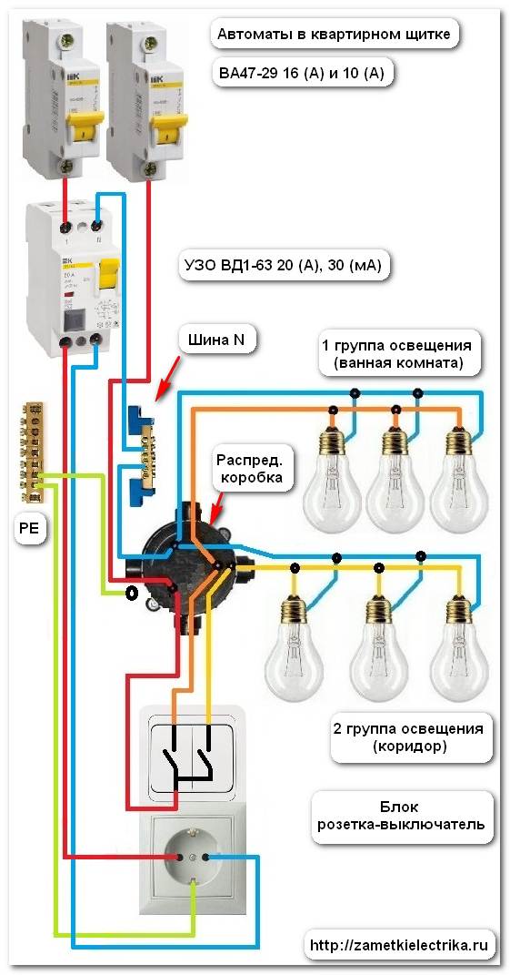
- Typically, a home's power supply diagram looks like this. The cable or SIP wire from the meter is connected directly to the busbars of our distribution board. Separate power supply groups are powered from these buses. Each group has its own power circuit breaker installed on the phase wire. The neutral and protective wires of each group should not have switching devices.
Note! The neutral wire of individual groups can have a switching device only if connected through an RCD. The RCD can be installed either on a separate group or as an input for all groups. The issue of choosing the location for installing the RCD is not regulated by the PUE norms and remains a controversial issue. But based on operating experience and the personal opinion of the author of these lines, we advise you to install them separately for each group.
- Next, the wire or cable from each group machine is mounted to the distribution boxes. Each group can have from one to several distribution boxes.
- From distribution boxes, electrical wiring is distributed to end consumers - sockets and switches.
Designing a home electrical network
Based on the above general diagram of the house's power supply, to design the electrical network, we first need to calculate the number of groups and distribute the loads among them. In order to do this, we need to decide on the wiring installation method and calculate the possible load of our consumers.
Choosing a wiring installation method
Let's start by choosing the method of installing the electrical network. Electrical wiring of a private house can be done in an open or hidden way. And not only the number of groups, wire cross-section and total installation cost, but also the appearance of the entire house depends on the right choice.
So:
- First of all, we note that any type of wiring installation can be implemented in a house of any design and from any building materials. The only question is the cost of installation work. We will not provide installation standards for different types of wiring in different conditions. You can find this information in other articles on our website. Let's focus only on generally accepted norms.
- Open wiring has found wide application in houses made of flammable materials. First of all, this is wood, SIP panels and other types of flammable building materials. For such houses, the cost of installing open wiring is often much lower. Hidden wiring will require considerable financial investment, and its installation is labor-intensive.
- Hidden wiring is used mainly in houses made of brick, foam blocks and other non-combustible materials. After all, this type of wiring allows you to completely hide utility networks, while at the same time, in houses made of non-combustible materials, it does not impose any special requirements.
Calculation of the total load of the house
At the next design stage, you need to calculate the total load on the house and on individual electrical receivers. This is necessary for the subsequent formation of groups.
- To do this, we first need to determine the number of electrical points and their maximum power consumption. This often becomes the most serious problem for non-professionals, but de facto there is nothing difficult about it.
- Each socket or switch in the house is mounted for a specific electrical appliance or group of electrical appliances. We just need to select the most powerful of them and then carry out calculations for it.
- The power of an electrical appliance can be viewed in the device passport. It may also contain an instruction manual. If you don’t have one or the other, then you can find out the approximate power in our table.

- But in most cases, the power of devices is indicated in Watts, and we need to convert it into Amperes. To do this, you can use Ohm's law - . In general, this is a simplified version of the formula, but for our purposes it is quite sufficient. Based on this formula, it turns out that an electrical appliance with a power of 1 kW for a 220V network consumes an electric current of approximately 4.5A.
Distribution of loads by groups
After we have calculated the total load in the house and for each individual electrical point, we can begin to directly create groups.
So:
- According to clause 9.6 of VSN 59 - 88, the rated power of circuit breakers for powering group lines of sockets and lighting networks should not exceed 16A. Starting from this point, we distribute our loads into separate groups.
Note! To power powerful electrical receivers such as an electric oven, it is allowed to install group circuit breakers with a rating of 25A.
- Load distribution among groups should be based on their location and type of load. So quite often the group lines of the lighting network are separated from the power supply groups of the sockets. But this is not mandatory, and in some cases it is not advisable.
- It is also worth remembering that it is not easy to install electrical wiring in a private house yourself. Therefore, you should not place different electrical receivers of the same group in different parts of the house. Usually these are 1 - 2 adjacent rooms.
- Another aspect that is worth paying attention to is clause 7.2 of VSN 59 - 88. It requires connecting sockets in the kitchen and living rooms to different groups. Quite often, the kitchen outlet group also includes an outlet in the bathroom.
Note! Sockets in the bathroom can only be installed if there is an RCD circuit breaker in the group in which the socket is installed. Moreover, according to the PUE, the rated leakage current for such a switching device is normalized by a leakage current of 30 mA.
- As a result, we can get from 3 to 7 groups depending on the total load. Some may end up with more than 10 groups. But here everything depends on the size of the house and the number of electrical appliances. But according to the technical conditions, the introductory circuit breaker, which is installed in a house, rarely exceeds the value of 25A, sometimes 40A.
- This should be remembered when dividing the load into groups with your own hands. After all, the likelihood that all electrical appliances will work at the same time is quite low. Therefore, you should approach this issue soberly and perform the distribution more carefully, taking into account such a factor as the utilization rate.
Wiring selection
Before you carry out electrical wiring in a private house yourself, you should also worry about calculating its cross-section. After all, its durability and fire safety depend on this factor. This issue is especially relevant for houses made of combustible materials.
- According to clause 7.1.34 of the PUE, only copper cables and wires should be used in residential buildings since 2001. Previously, aluminum wires, which can often be found in old houses, were allowed.
- As for the cross-section of the wires, it should be selected based on the load on the group line. But in order to avoid making a lot of calculations and simplify the choice, you can proceed from the nominal parameters of group machines.
- In addition, when choosing a wiring cross-section, you should take into account the method of laying the wires. After all, the heat transfer for wires laid in a hidden and open way is different. In this regard, although slightly, their cross-section differs depending on the load.
- We make the choice according to Table 1.3.4 PUE. In addition to the loads and installation method, it also takes into account such a parameter as the type of wire.
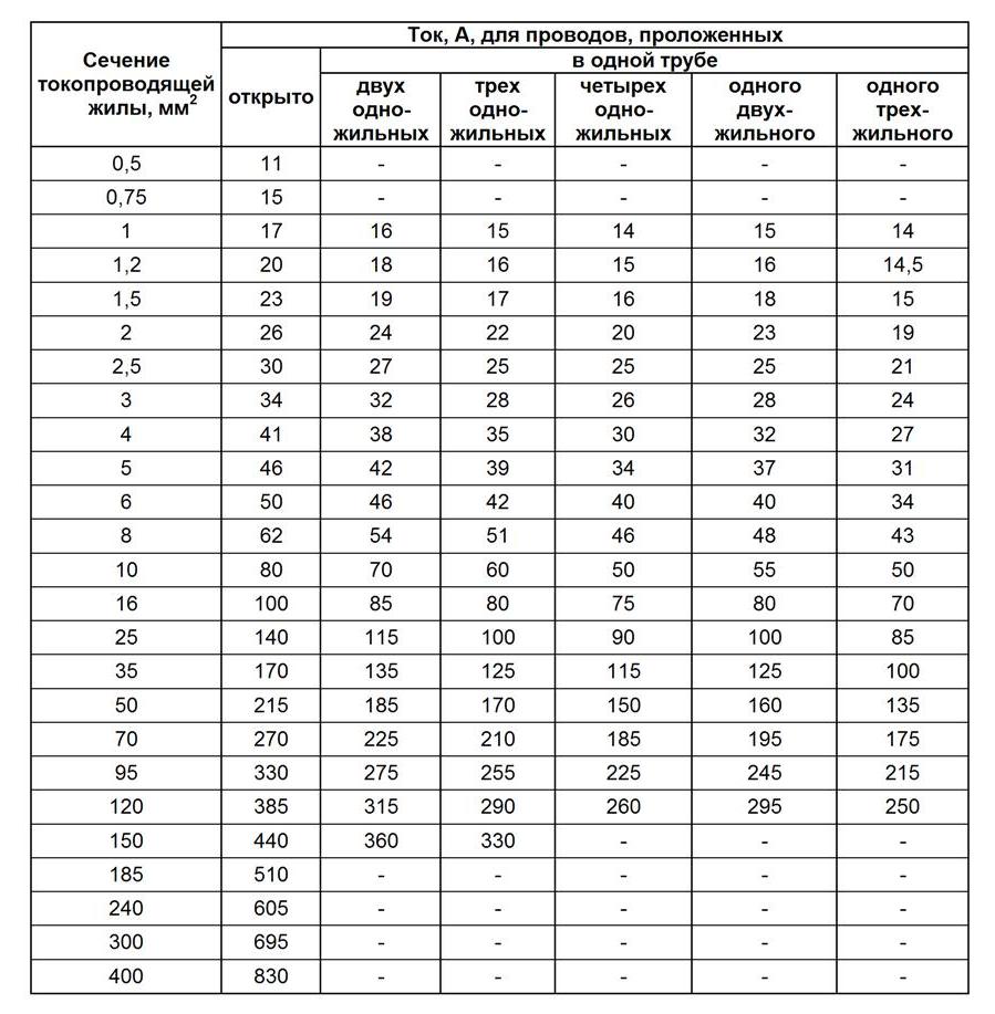
- But no matter how you choose the electrical wiring in a private house, you should remember that the cross-section should be no less than that given in the table. 7.1.1 PUE. For group lines it must be at least 1.5 mm 2.
Conclusion
In our article we presented the main stages of designing an electrical network in a private home. As you can see, there is nothing complicated about this, and the video on our website should make this task even easier. The main thing is to approach this issue carefully and carefully and you will probably succeed.
Not so long ago, owners of private houses connected to power lines independently. All you had to do was submit an application to the regulatory organizations and install a meter. Today the situation has changed radically. To connect to the electrical network, you need to provide a project describing how to power all appliances installed in the house (boiler, speaker, etc.). That is, the package of documents required to obtain a permit must necessarily include a single-line diagram of the system that ensures their operation. We’ll talk further about how to compile it, and how to properly arrange the power supply for a private home.
Country house electrification project. Three-phase or single-phase network?
Of course, before drawing any diagrams and going to make the connection, you will need to decide on the type of power supply, its source, etc.
In private houses, as in city apartments, a three-phase or single-phase network can be used. Both varieties have both their disadvantages and advantages. Initially, any industrial network has three phases. In high-rise buildings they are usually distributed among apartments. Moreover, due to the difference in the number of electrical appliances used, the load on the phase wires is often different. As a result, the neutral wire sometimes burns out. In a private house, such problems usually do not arise, since there is only one owner, and therefore it is much easier to control the load during phase distribution. However, if the network is used incorrectly, all sorts of problems - even failure of electrical appliances - can arise in this case as well. To prevent such troubles, you should use a stabilizer, which is very expensive. In addition, you will have to purchase equipment and elements designed specifically for a three-phase line. Which will also cost a pretty penny. Therefore, a three-phase power supply circuit for a private home should be used when there is really a need for it. That is, if it is planned to install very powerful devices or equipment - machines, electric stoves, etc.
The advantage of single-phase networks is their relative low cost and ease of use. The disadvantage is that the power is not very high. It is more appropriate to install such a network in small residential or country houses.
Autonomous power supply
One of the important conditions for comfortable living in any building is the constant availability of current in the network. However, unfortunately, when the power supply to a private home is supplied from a common power line, problems often arise associated with interruptions in its supply. A good way out of this situation could be the additional use of autonomous power supplies. These include:
- UPS. In the event of a power outage, this device begins to function instantly and automatically.
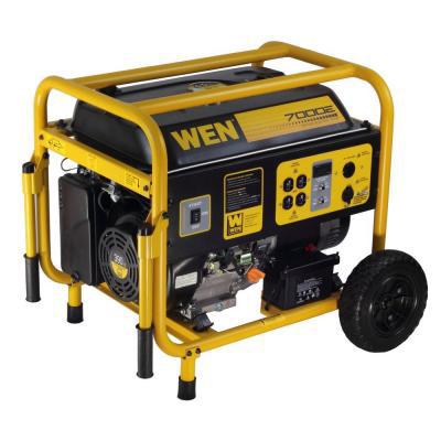
- Generator. Such equipment runs on gasoline, diesel or gas. It can also turn on automatically. The operating time depends only on the amount of fuel. With enough power, a generator can provide electricity to even a very large home for a long time.
How to get permission to connect
So, you have decided on the number of phases, the type of additional power supplies, etc. What's next? In what order is a private house connected to power lines? The power supply to country buildings is controlled by the network supply company in whose area of responsibility they are located. You will need to contact its specialists and collect the necessary package of documents. Their list should be found out in advance.
After receiving the documents, the network company will prepare technical conditions for power supply to a private home. Most likely, they will have to be coordinated with various related organizations. Next, a contract is concluded. After the network is installed, a representative of the network organization comes to the site and checks it for compliance with the requirements set out in the technical specifications. The inspection is carried out with the participation of all interested parties. Next, Rostechnadzor issues a permit to operate the network.
Single line diagram
First, let's look at what such a drawing actually is. A single-line diagram is essentially the same basic diagram, but executed in a simpler form. That is, all lines, both single-phase and three-phase, are indicated on it by one line. There is no detailed detail in such diagrams. Therefore, they are compact and at the same time give a fairly clear idea of exactly how the power supply of a private home is carried out.
There are some rules for drawing up such schemes, which we will discuss further. They are not particularly complex, but you need to know about them. Otherwise the project will not be accepted.
Purpose of compilation and basic requirements
A private home is an important document according to which all installation work is carried out. It must be compiled in such a way that:
- The safety of using electrical equipment in terms of electric shock was ensured.
- It was guaranteed that there was no risk of a fire in the house due to short circuits, melting wires, etc.
- During the operation of the building, the people living in it had the opportunity to easily use all the modern powerful electrical appliances they needed.
These are the main requirements for this document.
What types exist
Such a simplified power supply diagram for a private home can be:
- Executive. Most often, this option is drawn up during the operation of the facility. For example, if you need to make any changes to the current system or for some reason there is a need to provide information to the energy sales company. Before drawing up the diagram, the line in this case is simply examined visually.
- Calculated. Such a diagram is drawn up before installing the system, for example, in a new house or when completely replacing the old electrical wiring. In this case, all the necessary calculations are made (loads, cable cross-sections, etc.), as well as the selection of suitable equipment (protection devices, etc.).
Compilation rules (symbols)
Of course, the linear power supply diagram for a private home must be drawn in compliance with all required standards. The latter are determined by GOST 2.702-75 and have been in force since 1988. They indicate which symbols should be used to represent certain elements of the electrical wiring of a house on a diagram. To display a three-phase connection, the following methods can be used:
- a crossed line with the number “3” placed next to the output or input,
- a straight line crossed out with three slashes.
To designate devices, switchboards, sockets, etc., exactly the same symbols are used as in any other electrical circuits (GOST 2.709).
What should be present
A single-line power supply diagram for a private home must necessarily include the following elements:
- connection point to the electric main;
- brand of input device and rated current at the connection point;
- cable brand, cross-section and length (to the nearest meter);
- values of voltage loss in lines;
- calculated and actual power of the ASU, their cosφ and calculated current;
- brand of protective devices and their rated current;
- design loads;
- balance sheet boundary;
- type of AVR cabinet indicating its operating mode;
- commercial metering and control devices used.
How to draw
Of course, you can also draw a diagram on paper using a pencil and ruler. However, nowadays it is easier to do this on a computer or laptop. There are various software with which a power supply diagram for a private home can be drawn up quickly and without problems. After drawing, it is simply printed on a printer. For example, the program “1, 2, 3 diagram” is designed to create a single-line diagram of an electrical panel, and Semiolog allows you to create all the necessary labels. You can download this software from the official website, which guarantees the absence of “garbage” and viruses. Installation and use are free. “1, 2, 3 scheme”, among other things, allows:
- select the electrical panel housing in accordance with the requirements;
- equip it with modular devices;
- determine the connection hierarchy of the latter;
- create a ready-made diagram.
The program database contains current certified articles of the necessary equipment.
Load calculation
Thus, when drawing up a single-line diagram of the power supply at home, you will need to calculate the loads, voltage losses, determine the power of the equipment and how this is done, and we’ll talk further.
A residential private house, the power supply of which can be provided through either a single-phase or a three-phase network, will, of course, be equipped with a wide variety of electrical appliances. In order to calculate the load on the lines, you should add their power and divide by the voltage. The result will be the required current strength. Knowing it, using special tables you can determine whether the network is overloaded and what cable is needed for wiring. When performing calculations, you should take into account the power of not only existing electrical appliances, but also those planned for purchase in the future.
For some very powerful household appliances, for example, a washing machine, boiler or electric stove, it is best to install a separate cable. Often a separate line is provided to office equipment. In the case of using any professional equipment in a garage or outbuilding, as already mentioned, three-phase power supply to a private home is used.
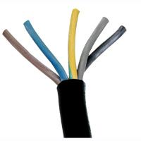
How to choose a cable for the network
For a single-phase connection you will need wires with three cores, for a three-phase connection - respectively, with five. When developing a project, it is very important to choose a cable of a suitable cross-section (guided by the PUE). This indicator can be found in special tables, depending on the current strength. The required diameter of the conductor is preliminarily calculated. This is done using the formula d=k×I+0.005. Here k is a constant coefficient for the metal of the conductor. For example, for copper it is 0.034. The letter I denotes the current strength.
They sell wires using cross-section rather than diameter as a measurement system. Therefore, it will be necessary to define it further. There is a formula for this: S=0.785×d2.
A preliminary calculation can be made based on the fact that per square millimeter of copper wire there can be 10 A, aluminum - 7 A. In practice, a wire of 2.5 mm 2 is usually used for sockets, and 1.5 mm 2 for lighting.
Selection of input device
The electrical connection to a private home is carried out through the so-called VU. They are metal cases that contain devices designed to control the building's electrical network. Models that also perform a distribution function are called ASU. Input devices are installed either on a pole or next to the building.
When choosing an ASU for a private home, the power supply of which must be safe and uninterrupted, you need to consider:
- The magnitude of the line voltage. Country houses are usually supplied with 220 V lines.
- Current frequency. This is a constant value and is 50 Hz.
- Neutral mode. This is the name of the grounding type. In the private sector it is usually carried out according to the TN-C scheme. In this case, the neutral and protective wires are pulled in one conductor. Their separation is carried out inside the control unit.
- Characteristics of short circuit current. Electrical circuit calculations usually take into account a short circuit on three live phase conductors. Calculations are made using special formulas.
- Installed power.
In TN-C systems, a single-pole input circuit breaker is usually used at 220 V, and a three-pole circuit breaker at 380 V. In the first case, the calculation of the power of the input device is calculated using the formula I р=P р/U Ф×cos Ф (where U Ф is phase voltage, Pp is calculated power, Cos Ф is active/reactive power). The power of the input device for a 380 V network is determined by the formula Ip=Pp/(√3xUhx cos f) (where Uh is the network voltage).

The rated current should be 10% more than the calculated one. Therefore, the final result is determined by the formula I t.r. = I p × 1.1.
AVR shields
A private home usually includes this element. AVR panels are designed to provide backup power in the event of a power failure in the main source. Additional inputs of these devices can be connected both to a fixed network and to a generator. There are these types of shields:
- With first input priority. In this case, when the voltage disappears at the main input, switching to the backup one occurs automatically. If a current appears, the reverse process occurs.
- No priority. Such devices do not automatically switch back to the main input when voltage appears on it. In this case, this procedure is performed manually.
- With partitioning. In such devices, power is supplied through a system of switches installed at the inputs. If the voltage fails on any of them, the third switch begins to function, supplying voltage to de-energized consumers from the working input.
- With DGU. In this case, when the voltage on both inputs fails, the generator starts. When main power is restored, the system returns to its original state. The power supply to a private home using this option will be uninterrupted in any case.
ATS shields, among other things, can differ in design. For a current of 25-160 A, mounted models are used, for 160-400 A - floor-standing. Cables enter and exit through a hatch at the bottom of the housing. The components are installed inside the cabinet on a special panel.
Basic rules for electrical wiring
Of course, the power supply of a private home must be arranged in compliance with all necessary rules. This also applies to such operations as wiring cables throughout the premises. Directly starts through a hole in the wall. It is best to run cables indoors in tubes embedded in the walls during construction. In this case, if necessary, it will be possible to easily replace any wire that has become unusable. Each pipe should be filled with cable no more than 40%. This will ensure easy dismantling. Also, closed wiring is sometimes installed behind suspended or suspended ceilings, along walls covered with plasterboard on a frame, etc. In this case, plastic or metal pipes are also used.
The internal power supply of a private wooden house is provided by installing open wiring. The cables are pulled in special plastic channels. The height of their position on the walls is not standardized. Lighting, power and low-current wires cannot be pulled simultaneously in one channel. Distribution boxes are installed at branch points in both open and closed systems.
All electrical installation work begins with the circuit diagram. If you have a clear and well-thought-out diagram at hand, therefore, wiring electrical communications at home will be quite simple. In this article, we will discuss the question of how the electrical wiring diagram in a private home is drawn up, its potential purpose and advantageous factors.
A schematic representation of the locations of electrical consumers and wiring is necessary in order to first of all stock up on all the necessary materials for work. If you have a diagram, then you can quickly calculate the cross-section of the conductors, their length and the number of other elements (sockets, distributors, switches).
For work on introducing electrical supply into a house, it is necessary to attract special labor, and the installation diagram of electrical wiring in a private house must indicate how the cables were inserted. This will come in handy later.
In modern conditions and thanks to the development of various technologies, it is possible to conduct electricity into the house in two optimal ways:
- using underground laying of cables in a special insulating material;
- and by air, if the distance from the house to the support allows this. Otherwise, an additional pole is installed.
Speaking about the air input option, it should be emphasized that conductors come to the main transformer of the house:
- phase (L);
- combined protective and working zero (PEN).
Important! Thus, home improvement is provided with single-phase power.
According to new standards, they began to practice installing metering devices on the outside of the house, so in addition, a panel and a subsequent machine must be placed in the room itself. In such cases, it is also advisable to install an RCD to protect residents from electrical injuries.
A cable comes out from the input metering device and goes to the internal panel, and cables are directly routed from it throughout the house. For complete reliability of home electrification, the network should be divided into several subsystems: for individual rooms, for the kitchen or dining room and rooms with high humidity (bathroom, bathroom).
Please note that the number of machines in the electrical panel must correspond to the number of groups into which you divided the power supply. For large houses, it is necessary to divide the systems into each separate floor (if necessary, combine with a garage and outbuildings).
What to pay attention to when drawing up a diagram?
In fact, there is no basic algorithm for drawing up diagrams; all you need to do is meet your own needs and not invent anything. Consider the recommendations below when drawing up a diagram for electricity in the house.
- When creating a circuit taking into account powerful consumers and household appliances, such as a washing machine, oven, refrigerator, it is necessary to take into account the installation of grounding. It is important to depict it on a diagram for clarity of execution of the work. Here it is advisable to use three-core conductors.
- It is best to implement the prepared circuit with a cable structure with a cross-section of at least 2.5 square meters. mm. These sizes are ideal for installing sockets and lamps. Conductors with a cross section of 1.5 square meters are often used for lighting. mm.
- Try not to overload the sockets; it is important that the total power of connected consumers to one source does not exceed 4.5 kW. Therefore, you need to make each socket separately for the intended device.
This is what a three-phase electrical wiring diagram looks like in a private house.
And this is a single-phase circuit, which is used no less often, despite the large number of electrical equipment in each home.

We follow the diagram and install the electrical wiring
In order to correctly transfer the created scheme into reality, it is important to follow this simple algorithm:
- First of all, we make precise markings of the walls. Using a mounting pencil, draw out the places where the wires will be located. Remember, they go strictly in a horizontal position with a vertical lowering or lifting to sockets or switches;
Important! You cannot install cables diagonally in order to save material.
- sockets and switches are located at a certain distance from the floor. Of course, no one uses the old version anymore, which means they should be installed at a height of 25-30 cm from the floor, and switches 80-90 cm.
- make grooves for the cable and socket boxes. Place these devices so that they are easy to use. Special fasteners are inserted into the finished grooves, but instead of them, plaster can be used, which will securely fix the wires in the channels, after which a layer of plaster is applied.
 (1 ratings, on average: 5,00 out of 5)

