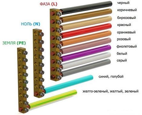
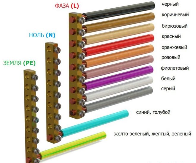
Connecting phases according to the color of the core insulation. Wire color according to purpose: phase, neutral and ground
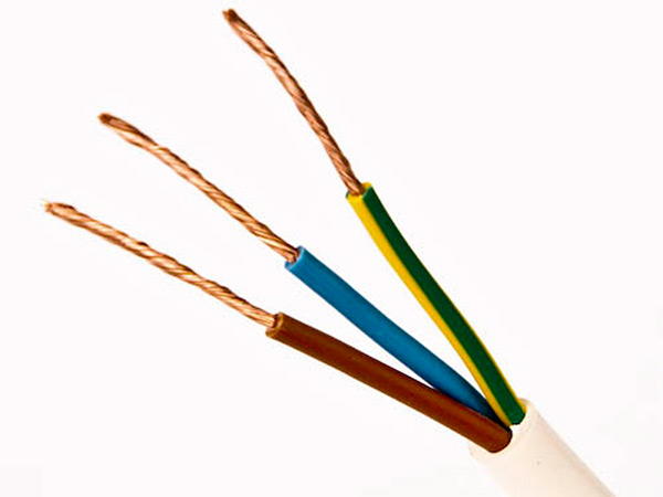
In order to facilitate the installation of electrical wiring, all cable and wire products have appropriate multi-colored markings. As a rule, in houses or apartments, lighting is installed and sockets are connected using three wires. Each of them has its own purpose in the home electrical network. Therefore, the designation of the color of the ground wires has great importance. Due to this, installation time and subsequent repairs are significantly reduced. Thanks to color coding, any type of connection is not particularly difficult.
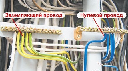
Ground wire
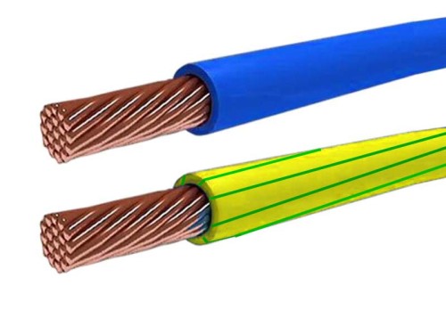
In most cases, the color yellow-green is used to indicate the ground wire. Sometimes you can find conductors with insulation only yellow color. Even less commonly used light green color. Typically, such wires are marked with PE symbols. However, if the ground wire is aligned with the neutral, it is designated as PEN. It is colored green-yellow and has a blue braid at the ends.
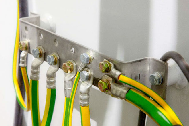
In the distribution panel, the grounding wire is connected to a special busbar, or to the housing and metal door. IN distribution box the connection is made with similar wires provided in lamps and sockets equipped with special grounding contacts. The ground wire does not need to be connected to the device protective shutdown(RCD), therefore such protective devices are used where only two wires are used for electrical wiring.
Neutral conductor (neutral)
For the neutral conductor or neutral it is traditionally used Blue colour. The connection in the distribution panel is made through a special zero bus, designated by the symbol N. All blue wires are connected to this bus.
The bus itself is connected to the input via. In some cases, the connection can be made directly, without any additional automatic devices.
Everything in the junction box neutral wires blue ones are connected together and do not take part in switching. The exception is the wire coming from the switch. Connecting blue wires to sockets is done using a special zero contact, designated by the letter N. This marking is affixed to the back of each socket.
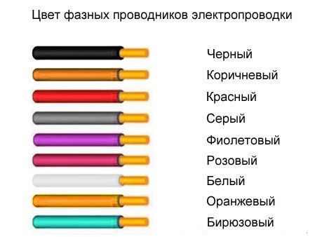
Phase wire color
The phase does not have any precise designation. Black, brown, red and other colors other than green, yellow and blue are quite common. In the distribution panel installed in the apartment, the connection of the phase wire coming from the consumer is made with a contact circuit breaker, located below. In other circuits, this conductor may be connected to a residual current device.
In switches, the phase is directly involved in switching. With its help, the contact is closed and opened - turned on and off. In this way, voltage is supplied to consumers, and, if necessary, this supply is stopped. In sockets, the phase conductor is connected to the contact marked L.
Wire Definition
Sometimes situations arise when it is necessary to determine the purpose of a particular wire if there is no marking on it. The simplest and most common way is. With its help, you can accurately determine which wire will be phase and which will be neutral. First of all, you need to turn off the power supply to the panel. After this, the ends of the two conductors are stripped and separated to the sides away from each other. Then you need to turn on the electricity supply and use the indicator to determine the purpose of each wire. If the light bulb lights up upon contact with the core, this is a phase. This means the other core will be neutral.
If there is a ground wire in the electrical wiring, it is recommended to use a multimeter. This device is equipped with two tentacles. First the measurement is established alternating current in the range of more than 220 volts at the corresponding mark. One tentacle is fixed at the end of the phase wire, and the second one determines grounding or zero. In case of contact with zero, the device display will display a voltage of 220 volts. When you touch the ground wire, the voltage will be noticeably lower.
Marking
There is not only the color of the wires phase, zero, ground, but also other types of markings, primarily alphabetic and digital designations. The first letter A indicates the wire material - aluminum. If this letter is missing, the core material will be copper.
Basic marking of wires in electrical engineering:
- AA - corresponds to stranded aluminum cable with additional braiding made of the same material.
- AC - additional lead braid.
- B - the presence of protection from moisture and additional braiding made of two-layer steel.
- BN - non-flammable cable braid.
- G - absence of a protective shell.
- R - rubber shell.
- HP - rubber shell made of non-flammable material.
In the vast majority of cables different colors core insulation This was done in accordance with GOST R 50462-2009, which sets a standard for marking l n in electrical equipment (phase and neutral wires in electrical installations). Compliance with this rule guarantees quick and safe work masters on the big industrial facility, and also allows you to avoid electrical injuries during independent repairs.
Variety of colors of electrical cable insulation
The color marking of wires is varied and varies greatly for grounding, phase and neutral conductors. To avoid confusion, the PUE requirements regulate what color ground wire to use in the power supply panel, and what colors must be used for zero and phase.
If installation work carried out by a highly qualified electrician who knows modern standards of working with electrical wires, you will not have to resort to help indicator screwdriver or multimeter. The purpose of each cable core is deciphered by knowing its color designation.
Ground wire color
From 01/01/2011 the color of the grounding (or grounding) conductor can only be yellow-green. This color marking of wires is also observed when drawing up diagrams on which such conductors are signed with the Latin letters PE. The coloring of one of the conductors on cables is not always intended for grounding - usually it is done if there are three, five or more conductors in the cable.
PEN wires with combined “ground” and “zero” deserve special attention. Connections of this type are still often found in old buildings, in which the electrification was carried out according to outdated standards and has not yet been updated. If the cable was laid according to the rules, then blue insulation was used, and yellow-green cambrics were put on the ends and joints. Although, you can also find the color of the grounding (grounding) wire exactly the opposite - yellow-green with blue tips.
The grounding and neutral conductors may differ in thickness; they are often thinner than the phase conductors, especially on cables that are used to connect portable devices.
Protective grounding is mandatory when laying lines in residential and industrial premises and is regulated by PUE standards and GOST 18714-81. The neutral grounding wire should have as little resistance as possible, the same applies to the grounding loop. If all installation work is carried out correctly, then grounding will be a reliable protector of human life and health in the event of a fault in the power line. As a result, correctly marking cables for grounding is critical, and grounding should not be used at all. In all new houses, wiring is done according to the new rules, and old ones are put in line for replacement.
Colors for neutral wire

For “zero” (or zero working contact) only certain wire colors are used, also strictly defined by electrical standards. It can be blue, light blue or blue with a white stripe, regardless of the number of cores in the cable: a three-core wire in this regard will be no different from a five-core wire or with an even larger number of conductors. In electrical circuits, “zero” corresponds to the Latin letter N - it participates in closing the power supply circuit, and in circuit diagrams it can be read as “minus” (phase, respectively, is “plus”).
Colors for phase wires
These electrical wires require especially careful and “respectful” handling, since they are live, and careless touching can cause serious injury. electric shock. The color marking of wires for connecting a phase is quite varied - you cannot use only colors adjacent to blue, yellow and green. To some extent, it is much more convenient to remember what the color of the phase wire may be - NOT blue or cyan, NOT yellow or green.
On electrical circuits, a phase is designated by the Latin letter L. The same markings are used on wires if color markings are not used on them. If the cable is intended to connect three phases, then the phase conductors are marked with the letter L with a number. For example, to create a diagram for three-phase network 380 V used L1, L2, L3. In electrical engineering, an alternative designation is also accepted: A, B, C.
Before starting work, you need to decide what the color combination of wires will look like and strictly adhere to the chosen color.
If this question was thought through at the stage preparatory work and taken into account when drawing up electrical wiring diagrams, you should purchase required amount cables with cores of the required colors. If after all the right wire ended, you can mark the wires manually:
- ordinary cambrics;
- heat-shrinkable cambrics;
- electrical tape.
About the standards for color marking of wires in Europe and Russia, see also this video:
Manual color marking
It is used in cases where during installation it is necessary to use wires with cores of the same color. This also often happens when working in old houses, in which electrical wiring was installed long before the advent of standards.

Experienced electricians, to avoid confusion during further maintenance of the electrical circuit, used kits that allow marking phase wires. This is allowed and modern rules, because some cables are manufactured without color and letter designations. The place where manual marking is used is regulated by the rules of the PUE, GOST and generally accepted recommendations. It is attached to the ends of the conductor, where it connects to the bus.
Marking of two-core wires
If the cable is already connected to the network, then to search phase wires Electricians use a special indicator screwdriver - its body has an LED that lights up when the tip of the device touches a phase.
True, it will only be effective for two-wire wires, because if there are several phases, then the indicator will not be able to determine which one is which. In this case, you will have to disconnect the wires and use a dialer.

The standards do not require such markings to be made on electrical conductors along their entire length. It is allowed to mark it only at the places of joints and connections of the necessary contacts. Therefore, if there is a need to apply marks on electrical cables without markings, you need to purchase materials in advance to mark them manually.
The number of colors used depends on the scheme used, but there is still a main recommendation - it is advisable to use colors that eliminate the possibility of confusion. Those. Do not use blue, yellow or green marks for phase wires. In a single-phase network, for example, the phase is usually indicated in red.
Marking three-wire wires
If you need to determine phase, zero and grounding in three-wire wires, you can try to do this with a multimeter. The device is set to measure AC voltage, and then carefully touch the phase with probes (it can be found and indicator screwdriver) and in series the two remaining wires. Next, you should remember the indicators and compare them with each other - the phase-zero combination usually shows a higher voltage than phase-ground.
When phase, zero and ground are determined, markings can be applied. According to the rules, a yellow-green colored wire is used for grounding, or rather a core with this color, so it is marked with electrical tape of suitable colors. Zero is marked, respectively, with blue electrical tape, and the phase is any other.
If during preventive maintenance it turns out that the marking is outdated, it is not necessary to change the cables. Replacement, in accordance with modern standards, only electrical equipment that has failed is subject to repair.
As a result
Correct marking of wires is a prerequisite high-quality installation electrical wiring when carrying out work of any complexity. It greatly facilitates both the installation itself and subsequent maintenance of the electrical network. To ensure that electricians “speak the same language,” mandatory standards for color-letter marking have been created, which are similar to each other even in different countries. In accordance with them, L is the designation of phase, and N is zero.
For electrical wiring and row installation electrical devices it is necessary to ensure the protection of equipment and the lives of consumers. For these purposes, a grounding wire is connected to the network.
Purpose
According to PUE requirements and GOST 18714-81 in residential and industrial premises installation of the system is required protective grounding, and also draw up a report on its availability. The principle of operation of grounding can be explained using the example of damage to a phase cable and the appearance of the so-called leakage current. In most cases, the wiring in the apartment is protected using a current interruption device or RCD. But the RCD is triggered only in the presence of differential current (which does not always appear and not immediately when the wiring is damaged).
Photo - operating principle and errors
Differential current appears only in cases where the device or conductor is connected to a certain point that has a different potential. The resistance force of the earth is very high and due to this the RCD is triggered. However, it cannot be argued that installing an RCD is a necessity. If protective device will not be connected to the wiring, then the current will simply flow to the grounded unprotected outlets of electrical installations, which will be under high voltage. This is not a critical situation, but it is very dangerous for the life of the average person - if you touch such a tap, you can get an electric shock.
Marking
The ground wire is identified using:
- Letter marking;
- Color.
Let's consider what color the ground wire is. In a three-core wire, grounding, according to the rules of the PUE, is indicated by the letters PE without providing separate information about the cross-section, its color is yellow-green (yellow in the plug). Cables consisting of four or more cores are marked in the same way. For some imported models, the designation may be in only one color - yellow or green. We also draw attention to the fact that often the thickness of the ground tap may be less than that of the phase tap - this is another feature of the zero and ground.
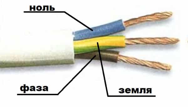
Photo - marking
IN certain cases stranded wire has limited space with visible insulation. Then limited marking is allowed electric cable. Minimum distance from open wire to insulation 15 mm.
Sometimes, if ground is not installed in a single-phase network, it can be used as protection copper wire for grounding without insulation. But then buy a copper electrode with a cross-section of 25 mm or more. Theoretically, such a system can work, but if possible, it is better to use special conductors.
The cable is also designated by a combination of letters and numbers. As we said above, the wire must be marked “PE”; in addition, the value of cross-section, length, brand, etc. may also be present.
Video: grounding and grounding
Connection
Installation neutral wire and grounding is necessary when connecting any electrical equipment. If you work in an apartment, then you need to determine the grounding wire in the panel, but if the installation is carried out in a private house, then a grounding loop is first installed. Let's consider both options.
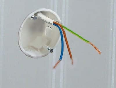
Photo - socket and ground
In almost every modern socket, chandelier and other outlets have a special grounding terminal, to which the protective cable must be connected. The apartments are connected via the TN-C system. In it, the connection of the ground loop is made using existing pipelines. Here several wires are connected to the risers: phase, neutral and ground. In newly built houses it is used TN-S system. How to distinguish them:
- Type TN-C is connected with four-core conductors;
- In TN-S - five-core.
Instructions on how to make ground in the TN-S network:
- The phase cable is connected accordingly to the phase;
- The zero wire is connected to the zero bus. To do this you need to use a special clamp. Please note that you cannot connect the ground and neutral wires together;
- Knot protective cable is brought to the wall of the shield - it is this that acts as a point with a different potential.
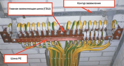
Photo - installation principle
In order to connect TN-C, there are several options. If you live on the lower floors apartment building, then you can make your own circuit - just drive and weld metal pegs together and connect the grounding to them. If at higher levels, then you can extend the ground from the basement (or, again, a homemade circuit) to the apartment wiring. To do this, you can choose a single-core wire, for example, flexible SIP, GPP or flat for grounding PV 3.
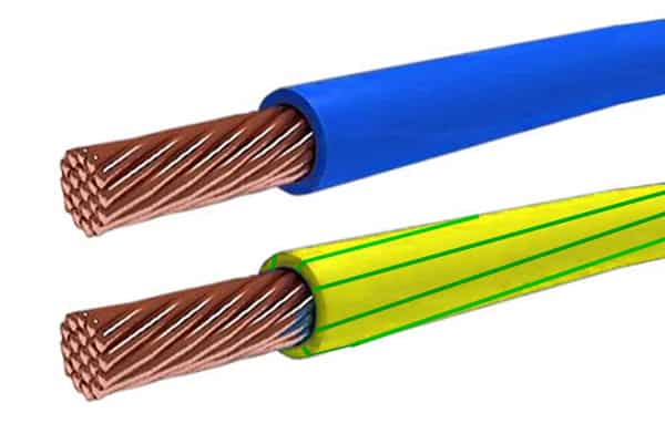
Photo - PV
Even in apartments, they arrange the ground using metal mesh trays. But, here the resistance must first be calculated. Measurement and verification of existing parameters is carried out with a multimeter.
Sometimes to connect protective systems craftsmen arrange connections with batteries, gas pipelines or pipes in the apartment. This is a very dangerous scheme, because if a current leak occurs, not only your apartment, but also your neighbors’ apartment will be energized.
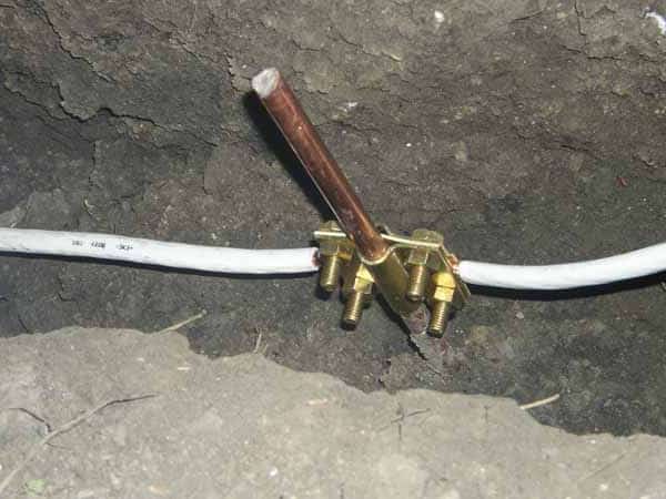
Photo - portable outline
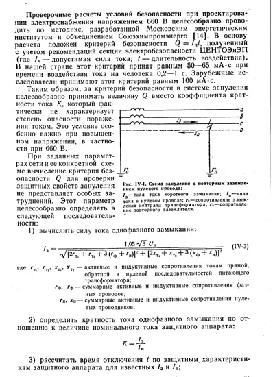
For the grounding circuit, a repeated or double ground is used. This method is described in the photo below, and a diagram is also shown there. Please note that the neutral cable is re-grounded every 200 meters.
To carry out grounding in a private house, it is necessary to organize a circuit. It is presented in the shape of an isosceles triangle. Metal pegs are driven around the perimeter, located at equal distances from each other. They are connected to each other by reinforcement that is welded to them. The cable end from the house is connected to the resulting closed circuit.
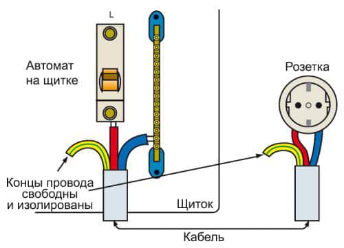
Photo - land organization
It looks like a portable grounding diagram. It is used to protect the cottage or professional electricians, if you need to test and take measurements from high-voltage overhead wires.

Photo - Set
You can buy a set of grounding wires for the KPZ-M, ShRN cabinet and the SSD KPZ-M container at any electrical store; their price depends on the type and area of use. There you will also find special clamps, anode grounding electrode and other necessary devices and circuit elements. Be sure to first check the certificate of quality and compliance with the necessary standards.
Without wires and cables, the functioning of production, energy, communications and many other industries is impossible. And not a single house or apartment is complete without wiring. How diverse are the problems solved using electrical networks, and the conditions in which they have to operate, the classification of existing products is just as large. So that the consumer can accurately purchase required product and correctly connect to the network, manufacturers must comply with generally accepted standards in the matter of marking wires by color.
Safety first
For people whose work is constantly connected with electricity, it will not be difficult to recognize the wires both by color and by alphanumeric markings. She will talk about:
- the material from which the cores and insulation are made;
- purpose of the cable;
- cross-sectional area;
- operating voltage and other features.
And for a person who deals with electricity at the household level, it is enough to understand the color marking of wires. Then it will not be difficult for him to determine the location of the phases and grounding. The risk of electric shock is reduced significantly, and repair or installation work is carried out much faster and without the involvement of specialists.
Specifics of various types of cable products
Before talking about marking, it is worth determining what the difference is between cable, wire and cord.
Various types of cables can be used not only on the surface, but also underground, in water. This is possible because one or more insulated cores are protected by a special sheath. She might be from various materials, capable of withstanding aggressive environmental conditions.
Concerning electrical wires, then they also contain wires or cores twisted or insulated from each other. They are covered with a protective non-metallic sheath or winding, which does not imply their laying in the ground.
A cord is a wire containing flexible and insulated conductors. Using this type of cable product, various networks are connected to the network. household devices, devices that are mobile or frequently move from place to place.
The classification of cable products depending on their purpose is as follows:
- Power products. These include SIP and VVG wires. The latter variety is suitable for installing electrical wiring and lighting indoors, connecting electrical installations. Self-supporting insulated wire(SIP) used in construction air lines power transmission and creation of branches to residential buildings and buildings. The number of conductive cores in products marked VVG varies from 1 to 6. For the SIP variety, this figure ranges from 1 to 4.
- The purpose of RF cables is to transmit a signal from one device to another.
- Control products are needed to power devices and are indispensable in systems remote control. GOST allows the number of conductive cores in them from 4 to 37 pcs.
- In order to coordinate the operation of instruments and devices at a distance, control wires are used along with the control type. Current-carrying cores in such products can be from 3 to 108 pcs.
- A separate type of communication cable will be required in order for subscribers to be able to exchange information at a distance. Within this group there is a division into high- and low-frequency types of products.
Color as a source of information
Color marking of wires has been used for a long time; it has proven to be convenient and informative. In this regard, no one is going to change it, and knowledge about it will be relevant at any time.
Chain direct current involves the use of only two wires: positive (“+” plus) and negative (“-” minus). Charge conductors with a minus sign are marked in black (or blue). The wires that carry a positive charge are covered in red insulation. The middle conductor in a DC circuit has a color blue color.
There are times when it is necessary to perform two-wire wiring, branching it from a direct current network with three conductors. Then the conductor with the plus sign will receive the color of the wire from which it is removed.
Direct current is used in construction and industry. It ensures the operation of loading electric vehicles, trolleybuses, and trams. At electrical substations, when powering automation circuits, a direct current circuit is also used.
Color designation of power and other types of cable products
Color marking for SIP or VVG wires comes down to the following rules:
- The yellow-green color will indicate grounding.
- Zero will give a blue or blue tint to the insulating material.
- The phase conductor will be brown or black. But the rules for electrical installations allow the marking color to change to red, gray and even purple shades.
IN single-phase networks, where there is practice in using SIP cables, the neutral working conductor can be combined with the grounding conductor. In this case, the marking will look like a yellow-green wire with blue marks, which are placed at both ends of the line during installation.
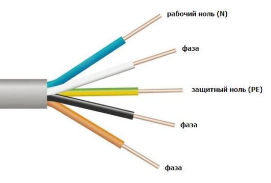
Three-phase AC networks assume that the SIP cable cores will have following colors:
- yellow, green and red for phases A, B and C respectively;
- blue color is reserved for highlighting the working zero;
- green-yellow color indicates grounding.
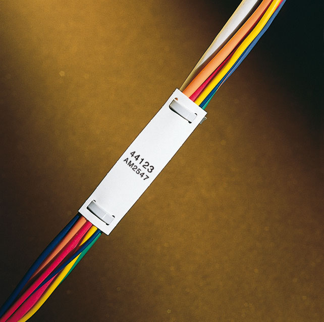
When a SIP cable is used during the installation of power lines, tags with information about the purpose and parameters are additionally attached to it. This marking also allows you to navigate objects where there are many wires of the same type.
Due to the fact that AC networks are created using color-coded SIP wires, not only the work at the installation stage is simplified. Color coding makes it easier to maintain and repair networks and helps reduce accidents. And the unpleasant consequences of electric shock can be fatal. Therefore, designating SIP wires and other types by color is a necessary precaution and a smart solution that makes the work of installers and users of electrical networks easier.
Color designation and marking of wires in electrical wiring. Color of the phase, ground, zero wire.
Color designation of phase, grounding, neutral wires
[PUE-7]
According to the seventh edition of the PUE (2002, Ministry of Energy of the Russian Federation), electrical wiring must provide the ability to be easily recognized along the entire length of the conductors by color:
· bluecolors - to indicate zero, zero working or middle conductor of the electrical network (N);
·
 two-color combinationgreen-
yellowcolors - to indicate grounding, protective or neutral protective conductor (PE);
two-color combinationgreen-
yellowcolors - to indicate grounding, protective or neutral protective conductor (PE);
·
 two-color combinationgreen-
yellowcolors along the entire length withbluemarks at the ends of the line, which are applied during installation - to indicate the combined neutral working and neutral protective grounding conductor (PEN);
two-color combinationgreen-
yellowcolors along the entire length withbluemarks at the ends of the line, which are applied during installation - to indicate the combined neutral working and neutral protective grounding conductor (PEN);
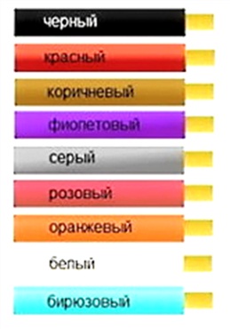
· black, brown, red, purple, gray, pink, white, orange, turquoise colors - phase, to designate a phase conductor(L).
Color designation by functional purpose
[GOST 12.2.007.0]
Color identification of conductors according to the functional purpose of the circuits in which they are used (according to GOST 12.2.007.0):
· for conductors in power circuits color- black;
· for conductors in control, measurement and signaling circuits of alternating current color- red;
· for conductors in DC control, measurement and signaling circuits color- blue;
· for zero protective conductors color - combinationgreen And yellow;
· for conductors connected to the neutral working conductor and not intended for grounding, color - blue.
Designation of wires by color
[GOST IEC 60204-1-2002]
According to GOST IEC 60204-1-2002 "ELECTRICAL EQUIPMENT OF MACHINES AND MECHANISMS" if color marking is used to identify wires, the following colors can be used: black, brown, red, orange, yellow, green, blue (including light blue), violet, grey, white, pink, turquoise.
Note- List of colors taken from IEC 60757.
For safety reasons, the colors green and yellow should not be used if they could be confused with a two-color combinationgreen- yellow.
The protective conductor must be easily recognizable due to its shape, location, marking or color. When using color designation, it should be a two-color combinationgreen- yellow. It is used along the entire length of the wire. This combination is intended for protective conductor only.
On insulated wires two-color combinationgreen- yellowshould be such that over a length of 15mm one of the colors covers at least 30%, but not more than 70% of the surface of the wire, and the other color covers the remaining part.
When the protective wire grounding easily distinguishable due to its shape, design, location (e.g. braided wire) or when insulated wire is not easily accessible, color coding is not necessary along the entire length. However, ends or accessible parts must be clearly markedgraphic symbol 417-IEC-5019 or two-color combinationgreen- yellow.
When a circuit includes a neutral wire, indicated by color, the latter must belight blue(IEC 60446, 3.1.2). Where possible, light blue should not be used to indicate other wires.
In the absence of a neutral wire, the light blue wire can be used for other purposes, but not as a protective wire.
When color coding is used, non-insulated wires used as neutral wires should be marked with a light blue stripe with a width of 15 to 100 mm , a color that is duplicated on every shell, equipment, or available location, or is painted a light blue along its entire length.
Identification of other wires should be carried out using color (either as a whole, or in one or more stripes), numbers, letters, or a combination of these. The numbers must be Arabic, the letters must be Latin (uppercase or lowercase).
Insulated unipolar rigid wires must have the following color designation:
· black- AC and DC power circuits;
· red- AC control circuits;
· blue- DC control circuits;
· orange- interlock control circuits powered by an external energy source.
Exceptions to the above are permitted:
· for internal cables on independent devices purchased separately with complete set cables;
· when used insulating material impossible to paint in the desired colors;
· when multi-wire cable is used, except for the green-yellow two-color combination.
 (1 ratings, on average: 5,00 out of 5)