How to check the neutral wire. Indicator screwdriver: types, device and methods of use
It is easier to work when the electrical supply circuit of the house is properly grounded; we will show that there is always a way out. Let us explain how to understand where the phase is and how to find out where the zero is. Grab your favorite M890S! Let's see how to determine phase and zero with a multimeter.
The simplest methods for finding phase and zero with a multimeter
A properly organized home grounding circuit eliminates problems. Firstly, PEN insulation is yellow-green in color. It is impossible to confuse it with the brown (red) phase and the blue neutral. It happens that the wiring is laid in violation of the requirements, the colors are mixed up, or missing altogether ( aluminum cable). We search for phase with a multimeter using a simple algorithm:
- Let's say an apartment has three wires: phase, neutral, ground.
- We set the multimeter to the AC voltage range of 750 volts and begin testing the wiring in pairs.
- Between the phase and any other wire there will be 230 volts (rms value), the ground-neutral jumper gives approximately 0.
Multimeter
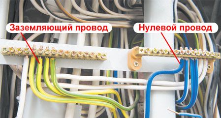
The access panel has at least five wires, three phases. The further process is determined by the imagination of local electricians. Good masters hang stickers A, B, C, indicating the location of the phases. Grounding is yellow-green, neutral is often blue.
Between adjacent phases the voltage is 380 (400) volts. High-rise apartments are sometimes supplied with two phases. Electric stoves with a power above 10 kW they try to divide the consumption. Wiring requirements are reduced. We advise you to immediately take a marker and mark the insulation with the required colors. A house without grounding usually receives two wires: phase, neutral. The substation transformer drives three phases. How many will be in the apartment should be found out.
Problems will begin when there is no wire marking, the phase comes alone. Between dangerous wires the voltage will be... zero!
- Two wires carry a phase, one neutral, they forgot to lay the grounding. There is a round zero between the supply wires; when evaluating the neutral wire, we get 230 volts. The situation looks like the phase conductors are neutral and zero. We made a mistake when laying the pipes - what can you do? We need to look for an additional source of support. An indicator screwdriver will do.
- Two wires of one phase, the second pair is grounding, neutral. They will show zero in pairs, crosswise - 230 V. Use a reference point.
There is no probe-screwdriver, with the help of a tester, no matter how you change the wiring, the problem will remain. It is necessary to have a reference source that is guaranteed to be grounded. Suitable:

Due to the variety of techniques, unreliability is recommended before starting serious work carry out tests. Measure the potential between the indicated reference points and the phase of the socket. Is the distance between the landmark and destination point large? We take an extension cord. The power filter is especially good personal computer, equipped with a characteristic illuminated button. The phase is on the left, the left pin of the plug (depending on which side you turn) is marked with a marker.
Then we call with a socket (without power, of course), make a mark with the right side. Let us explain, you can do without this; it’s better to put aside jokes with electricians. All that remains is to find the phase using the M890S. We set the range above 380 volts (between two phases), and begin to measure the potential difference between the terminals and the shield. We believe that the further algorithm is clear.
Correctly measure phase consumption
Let's measure the phase load. To install the right machines, maintain uniform consumption. According to the rules of a three-phase network, each branch is loaded equally, avoiding distortions on the supplier’s side. Let's evaluate which phases are included in the apartment. It’s easier to look at the entrance panel. An inexperienced person should avoid interfering. It is very easy to get an electric shock.
The house is old - in plain sight you can find a large steel plate that is clearly connected to the body. The designated is neutral. The house is powered by a three-phase voltage of 380 volts. Each apartment is often supplied with one phase. We see three clamps in addition to the ground terminal. Look where the wires go: automatic machines, switches (according to the number of apartments). A typical number of site neighbors of three simplifies the analysis task.
Now we know the method for finding the phase with a multimeter, we can safely (with caution, observing safety measures) poke with probes. Take care to set the correct range so as not to burn the device. Use measurements to confirm or refute your assumptions. There are two phases - load each equally. Examine the junction boxes, located near the ceiling (large round holes in the wall) in most older homes. Having turned off the supply to the apartment, armed with a tester, understand where and what is going. Use a radical method - cut off one plug, look where the power is lost.
The load of the two phases is uneven - correct it. It would be better to do it for automatic machines and traffic jams, which will have a positive effect on reducing the cost of switchboard equipment. To complete this topic, let’s say that the work rules provide for the implementation of such activities by at least two people. One is sure to insure and is ready to cut off the power supply, cut off the current-carrying wire, or kick the person suffering from an electric shock away from the dangerous territory.
Apartment power supply diagram with two phases
How to measure three-phase voltage with a multimeter
In this section we will rather talk about the specifics three-phase networks. Most multimeters can measure voltages up to 750 volts alternating current, which is quite enough to work with serious industrial networks. Each house is supplied from three phases. And what the industry calls neutral, we call neutral wire.
Enterprise networks are laid in two types:
- Mechanisms with isolated neutral The neutral wire is not used. Inside, the phase loads are equalized, currents flow through the same wires, of which there are three in total. If you get tired of looking for neutral, there is no line. Three phase wires will show a voltage of 230 volts relative to the ground, and 380 between them.
- The grounded neutral is neutral wire. Marked with the letter N on boxes. Useful to watch circuit diagrams industrial devices shown on the housing. Helps you understand the layout.
By mastering three-phase voltage techniques, everyone can better understand electrical wiring. multi-storey building. Where four wires rise from under the shield: three phases and a neutral.
Vehicle phases
Electrical networks help many objects. The car is relatively simple device. The basis of the supply is a 12 volt battery (actually 14.5 V), a generator, the output voltage level of which is regulated according to variations in speed. The voltage after rectification is suitable for feeding the on-board battery. The generator shaft is activated by the battery through a special regulating device.
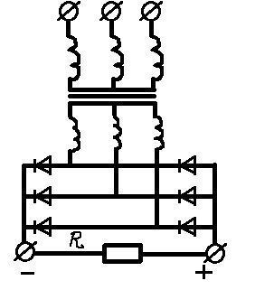
Three-phase Larionov circuit
Larion phase circuits rectified by a diode bridge power the car. A popular technique today. There are six diodes. The phases merge mechanically after rectification by a single line. Provides maximum power. Sensitive components of the car (on-board computer) additionally rectify unstable current. To extend the life of the device.
Next, the voltage goes to consumers. Wipers, display system, lighting, ignition. The on-board computer may issue a coded message: it’s time to check the phase sensor. An element whose operation uses the Hall effect determines the position of the engine camshaft. Equipped with similar washing machines, estimating the rotation speed. The car needs to determine the angular position of the shaft. The sensor emits pulses, evaluating the parameters of which the computer will receive the necessary information.
The car is stuffed with sensors. Two terminals supply power, the third generates a signal. To check, let's look at the diagram: the location of the nodes. Then we’ll get serious about dialing. To simulate the conditions for generating pulses, use a permanent magnet.
The question of how to determine phase and zero with a multimeter on a car should disappear. The support is the body of the car - the mass. It is clear that the generator only works when running engine. Inside the apartment we are looking for phase and zero, here the mass is given a priori. You can cause broken insulation (for example, diodes of a rectifier bridge). On a car it’s easier than ever to measure three phases with a multimeter. Effective value they said indirectly. About 20 volts (taking into account the losses of the imperfect bridge).
Multimeter User Mistakes
Chinese multimeters are configured to work even if the probes are placed incorrectly. Be careful not to accidentally break the device. Avoid doing the following: plug the black wire into the high current measurement connector, and the red wire into its place. Try to measure AC voltage high-voltage line - repair is guaranteed. Wrong ranges must not be used. For example, swear off trying to measure AC voltage using a DC scale. Checking the phases will be the last time in the life of the multimeter.
The device is damaged by high voltage of alternating polarity. Other things (for example, incorrect polarity of the probes) are not so bad.
So, imagine this situation - you need to connect new socket, but for some reason you do not know which of the wires at the output is phase and which is neutral. The situation is further complicated by the fact that there was no indicator screwdriver, nor a multimeter, which will allow you to quickly find which wire the voltage is passing through. Next, we will tell readers how to determine phase and zero without instruments!
Method No. 1 – Visual designation
The first and most reliable way to independently determine where the phase and zero are without a tester is to examine the color of the insulation of each conductor, based on which you can draw a conclusion.
The fact is that it is designed precisely so that you can find out which of the conductors is neutral and which is phase without instruments. To make it clearer for you and to be able to correctly determine the phase and zero, we provide a table with existing standards: 
As you can see, insulation can be of different colors, so it is better to remember that 0 is always blue, and ground is yellow-green (or only yellow/green). As a rule, the remaining third core is the phase that you need to determine. If there is no color marking, which is no exception, you can find phase and zero without a tool in other ways, which we discussed below!
Method No. 2 – Do a check
The second idea to determine without a tester where the phase wire is and where the neutral wire is in the socket is that you need the most available tools. Everything is very simple, you just need to find an incandescent lamp with a socket and two pieces stranded wire, about 50 centimeters long.
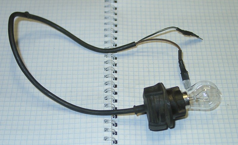 The conductors are connected to the corresponding connectors of the cartridge, one conductor is attached to the stripped to metallic color heating pipes, and the second one needs to “probe” the veins that interest you. The light will light up if you touch the phase contact. So simple way You can quickly find out without instruments where the phase and zero are.
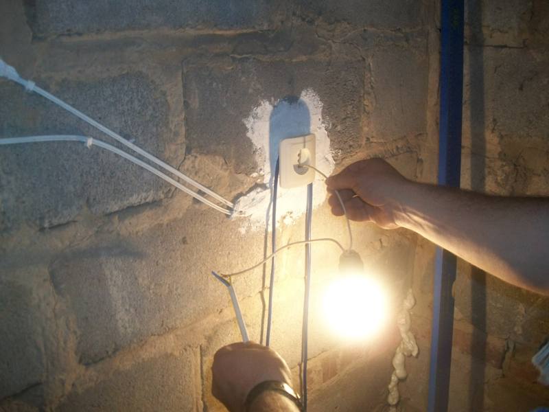
We draw your attention to the fact that this search option without instruments is dangerous and can cause injury. electric shock. Be careful when determining the voltage and be careful not to touch the exposed wire with your hand!
A simple sample made from improvised means
If you don’t have an incandescent lamp on hand, you can use a neon light bulb to assemble a homemade tester, which will also allow you to determine the polarity. The control scheme will look like this:

Method No. 3 – Potatoes to the rescue!
A funny, but still effective idea that allows you to determine phase and zero without an indicator, multimeter or other tester. All you need is a potato, 2 wires of 50 cm each and a 1 MOhm resistor. You can find the voltage using the method described above. The end of the first conductor is connected to the pipe, the second end is inserted into the cut of the potato, as shown in the photo. As for the second wire, one end of it needs to be inserted into the same section, at the maximum possible distance from the already inserted wire, and with the second you will feel those terminals on which you need to find phase and zero without instruments. The definition is as follows:
- If a slight darkening has formed on the cut, this is a phase conductor;
- No reaction occurred - you “found” zero.
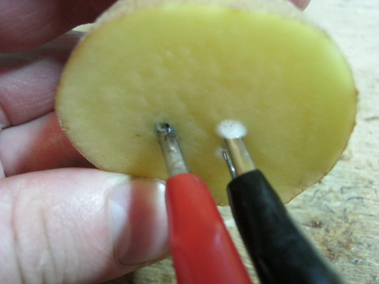

It should immediately be noted that in this case the determination should occur with a short delay of time when the vein comes into contact with the potato cut. You must touch the wire to the potato and wait about 5-10 minutes, after which the result will be visible!
Visual video lesson on how to determine polarity without instruments with your own hands
Using a similar technique, you can determine the polarity of contacts in a circuit direct current. To do this, two wires are lowered into a cup of water and if bubbles begin to form near one of them, as shown in the photo below, it means that this is a minus and, accordingly, the second wire is a plus.
Whether it is installing a switch or something else, there is always a need to determine the neutral and phase wires.
Honestly, this is a fairly easy procedure, but only if you have the necessary skills in working with electricity. This article will discuss how to deal with such issues.
Introductory part about the principles of operation of electrical appliances
We all know that almost all household electrical appliances require relatively little power - only 220 volts. And in order to connect the electrician to the plug, you need two wires (in some cases - three). So here they are:
- Phase.
- Null.
- Grounding (if insulation failure occurs, it will prevent electric shock). And why, you ask, does the common man need to know where the phase is and where the zero is?
First of all, this will be useful when replacing the switch yourself, if it should be installed specifically on the phase wire. Who doesn't know, this will allow us to repair lighting fixture without cutting off power throughout the entire house.
But not only them, but also household appliances that work with running water or have iron cases. And to connect them, you need to use not only zero and phase, but also grounding.
There are three ways to determine phase and zero. Let us consider in detail all their advantages and disadvantages.
Determine phase and zero using a phase indicator
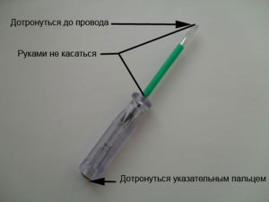
In this case, you will need a special probe, or as it is also called, an indicator. In general, this is an ordinary flat screwdriver with a plastic handle, where a visual sensor is placed - a neon or semiconductor lamp.

The procedure for determining the phase in this way is simple. You just need to touch the end of the tool to the right wire or plug it into an outlet. If voltage is present there, the screwdriver will light up with a faint light.
It is worth noting that this is possible with correct use screwdrivers: the finger of the palm in which the tool is located should be pressed against the metal part of the screwdriver. This will close the loop between ground and wiring, but there is no need to be afraid of this, since the same metal part The device significantly reduces the voltage.

Advantages: simplicity and accessibility of the method, a screwdriver can be bought at any store.
Flaws: risk of electric shock, albeit mainly on a psychological level.
Video on determining phase and zero using an indicator screwdriver
We determine phase and zero with a tester
More than one is used here modern device— phase tester. It will allow the owner to qualitatively measure the strength of alternating or direct voltage. To configure the device, a special rotary switch is used.
There are also two probes, the first of which must be inserted into the socket, and the second one must be held tightly in the palm of your hand. If we get to the neutral wiring, the display will show a slight voltage or several zeros. And if it is phase, then the voltage will be significantly higher.

Advantages: modern device, widely available on domestic market; higher measurement accuracy.
Flaws: no significant ones.
Video on determining phase with a multimeter
Determine phase and zero by marking
This is perhaps the most unreliable method. Its essence is as follows: today all wiring modern houses has a special color coded, depending on the purpose of a particular wire.
For example, a brown or black wire is often connected to a phase, and the one to zero should have blue tones. Regarding the grounding wire, it is made in two colors - green and yellow.
It’s a pity, of course, but in our country, the negligence of electricians often leads to the rules being ignored and thereby entailing the most unpredictable consequences. Therefore, under no circumstances rely on the integrity and professionalism of the workers installing electrical wiring in your home.
When the phase wire is determined, we bend it and begin to determine the neutral wire. They are attached to the panel inside the apartment in such a way that the grounding system as such is excluded. And if you have access to the panel, then you should inquire about the color of the wire that passes by the machines and identify it.
And if, because you want to be on the safe side or because direct access to the panel is impossible, then at any time you can use the good old remedy - a socket with a light bulb to which the wires are connected. And if you attach one of them or simply touch it phase wire, and connect the second wire to the remaining two wires in turn, then you can also determine the categories you need. If there is contact with zero, the light will light up, but if there is contact with the ground wire, then nothing will happen.

And, as if contrasting this method with a more advanced one, you can use the device we have already described - a phase meter.
In this case, you should take turns measuring the difference in voltage (in other words, potential) between all the wires and the already defined phases. In this case, the phase-zero category must significantly exceed all other categories (ground-phase).
Advantages: relative simplicity.
Flaws: insecurity.
So, together we figured out how to determine phase and zero.
This article is dedicated to practical problem, which is not uncommon in the practice of a home electrician - how to determine phase, zero and ground if there is a three-core cable, but there is no marking of what is where. But before we figure out how to find the phase, let’s remember what kind of animal this is.
A few words about electricity and common misconceptions
Direct current is taken from the battery and has two poles: plus and minus. The charge in batteries (accumulators) occurs due to chemical reaction. In this case, the charge occurs at the moment of closing “+” and “-”, so the batteries are stored and work for quite a long time. Simply put, the battery provides current when it is needed. Plus and minus indicate the direction of the current, and in devices polarity is important, so all direct current sources are marked. More precisely, we did not come across unmarked batteries, but if we were caught, they would be thrown away.
Alternating current is much more complex in nature. To understand how to determine, let's try to understand what the difference is. We do not pretend to be a dissertation, we are interested in the practical aspect, so we will try to explain it simply, and let the physicists laugh.
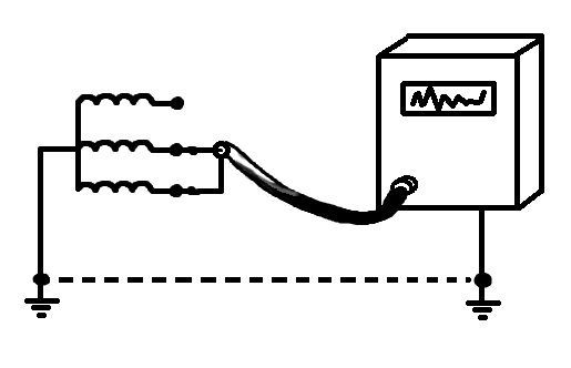
If you take a magnet, put it into a pipe on which three turns of identical wire are wound, and then start rotating the magnet, a current will appear on each of the three wires. The turns of the wire are shifted at an angle of 120 degrees, this shift is the phase. The current we receive will be three-phase. That is, the characteristics are the same, but if you imagine the current as a sinusoid, these three sinusoids will be shifted relative to each other. All this is used because if the resulting three phases are applied to the same pipe with a magnet, this current will create a rotating magnetic field, which is very useful in all electric motors, making them simpler and cheaper.
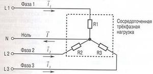
Let us add that the current is characterized by the potential difference between the wire in which the current arose and the neutral wire. The presence of this bridge (neutral wire) allows you to remove not three phases from the electricity generator, but two, or one. This is what happens in the transformer that powers your house or apartment. The voltage in the transformer is 380V, but the voltage between phase and neutral (neutral wire) is the same 220V that comes to our apartment. Phasing may differ for consumers, which means that three phases removed separately almost always have different loads. To correct the difference and combat overloads, grounding is used. The transformer uses the so-called. “solidly grounded neutral”, which allows you to correct load differences. This is possible due to the fact that the Earth (here our planet) has an infinitely low (zero) potential in relation to any electrical potential. Such a grounded neutral will drop a critical potential difference “to the ground” in case of danger.
The described process took about an hour, there was no damage, since most of time was devoted to precautions and safety. Safety is the main thing in this experiment!
We use an indicator screwdriver
We check all three wires in turn. Touching one of them will show a light in the screwdriver. The problem of how to find the phase was solved immediately, which means you can apply the first method in the light version - the last stage, immediately turning on the light bulb between the phase and one of the wires.
We use a multimeter
The photo shows a randomly selected multimeter that allows you to find phase, zero and ground in two ways. Maybe three.
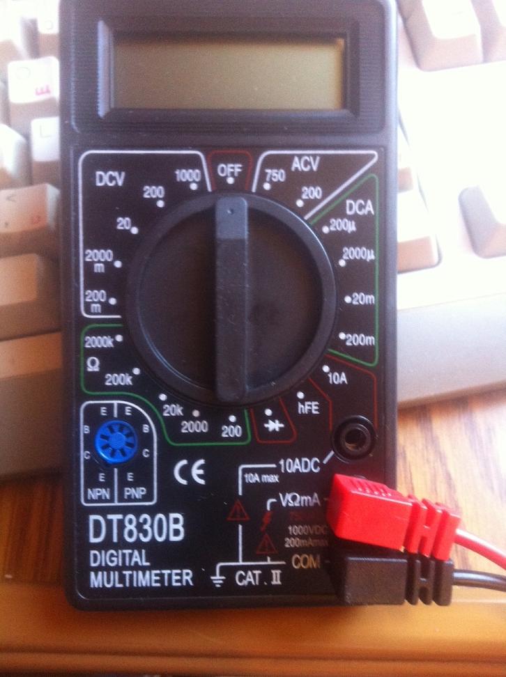
But even on specific example We will not show the position of the switch, this device requires understanding to operate.
We do not provide a description of the process of how to determine the phase using a multimeter, since the procedures may differ depending on the model. The instruction manual describes the procedures for each device, so learn what to do and how to do it from there.

There are no tools, but there is an RCD in the house
This will actually make things a little easier. We still need a sample. However, from the principle of operation we know that when the device is operating in the network, a short circuit between zero and ground will cause a current leakage, which will lead to the tripping of the RCD. This will help us accurately understand the zero-ground pair. Then we proceed in the same way, but you can immediately assemble the indicator lamp. In case of an error (short circuit phase - ground), the machine will turn off, the RCD will also turn off the power. That is, if there is an RCD, such an experience is generally safer.
Attention! The presence of an RCD does not cancel security measures, it is only additional insurance!
For "advanced" home electricians
We assume that such a person already has an indicator screwdriver and a multitester that he knows how to use.
Spend already 300 rubles (in Moscow prices in 2015), buy indicator screwdriver and multitester. Then spend two hours learning how to use them. This will save you a lot of time!
But let’s say the tester breaks down. He will take a 1.5 volt battery, a light bulb and a long wire, turn off the power to the panel and ring all three wires from the problem area.
Difficulty arises if the zero and ground wires are connected to the same terminal (there are panels with this design). In most cases, the neutral wire will be on the neutral bus. With this approach, the question of how to determine the phase is not a question; we have answered it. And we determine zero by disconnecting one of the wires (if they are on the same terminal), while we do not know whether we disconnected zero or ground, and by ringing the disconnected wire to the socket sitting on the same machine, in which we know exactly where each wire is. Of course, having previously de-energized the entire circuit. Disconnection is necessary to isolate two wires - ground and zero, since they have common points contact!
In this case, the color of the veins in one area may differ, this is the problem. But in any case, by ringing the disconnected wire, we find out where it came into the marked socket: to the contacts or to the petals of the earth. Such a search can only be carried out understanding the design of the shield and having practical skills !
In fact, we have described a process that allows you to quickly and safely determine both phase and zero with ground.
A few more ways that allow you to answer how to determine the phase
A voltmeter will allow you to measure the voltage between the heating battery (if it is metal) and all three wires. In this case, the phase will give 220V, zero approximately 10-30V, and ground zero. The same can be done with a multitester (if the function is available), not forgetting to clean the spot on the battery for good contact.
If there are old fuses that have nowhere to go, take one with pliers with good insulation and first short-circuit two wires, if it burns out, it is phase-ground, if not, ground-zero, or phase-zero. Also write down your observations, take the second fuse and, following the circuit described in the first part, close the remaining ones to finally determine both zero and phase with ground. If done correctly, you will need one or two fuses. One of the most safe ways in the absence of instruments.
When solving this problem, keep in mind that the wiring is not perfect. When determining in this case, a problem arose - it was not possible to determine the phase, zero, ground. Only a specialist helped to detect a short circuit in two wires. Therefore, the damaged core was excluded and insulated.
![]()
The sockets here are not grounded. In general, the task of finding the belongings of a cable is not uncommon, especially for those who deal with their electrical network from time to time. Usually in such farms even the machines are not marked, not to mention the wires. Although the task is to mark the entire network in two-room apartment took the author of the article only five hours. Take note...
As you know, the electricity that is supplied to our house is three-phase. The voltage between any two outputs is 380 V. At the same time, we know that the voltage used in household appliances is 220 V. How is one converted to the other?
The neutral wire plays an important role here. If you measure the voltage between one of the phases and this wire, then it will be exactly 220 V. More than modern sockets, an additional zero output is provided - this is the so-called protective zero.
A natural question arises: what is the difference between the two mentioned zeros? The first of them, the “working zero” (we are trying to determine it) is a neutral contact on three-phase installation generator substation connected to the neutral contact of a three-phase installation in a house or a separate entrance.
It may not be grounded at all. The main purpose is to create a closed electrical circuit when eating household appliances. In the second case, we are talking specifically about. This is usually called "protective grounding".
Due to enough complex nature AC, there are some typical views on the neutral wire and grounding, which may not correspond to the real state of things:
- “At zero there is no voltage at all.” This is wrong. It is connected to the neutral connector at the substation and is designed to create a potential difference at the output. Sometimes it is energized.
- “If there is grounding, then short circuit There definitely won’t be.” In most cases, this is true. But if the current increases too quickly, it may not have time to escape through the grounding in time.
- “If two wires in a cable are the same, and the third is different, then this is probably ground.” It should be that way, but sometimes it isn't.
Determination methods
Digital multimeter
Determining zero and phase using a multimeter. This device is very useful for working with electricity. It includes various features. It can be an ammeter and a voltmeter or ohmmeter.
Also, depending on the specific type, there may be other capabilities (for example, frequency measurement). These devices can be either analog or digital.
Using an indicator screwdriver. This screwdriver has a transparent handle. If you insert it into the socket in a certain way, then when it hits a phase, the light bulb will light up.
There are several designs of such screwdrivers. In the simplest case, when testing, you need to touch the end of the handle. Without this, the light will not light up.
During visual testing, the purpose of the wires can be determined by their color.
Using a special phase. This is a small digital device that fits in the palm of your hand. One of the wires must be held in your hand, the other is used to check the phase.
Step by step instructions
Let's talk in more detail about how to carry out such work.
When using a multimeter, you need to correctly set its operating range. It should be 220V for AC voltage.
With its help you can solve two problems:
- Determine where the phase is and where the “working zero” is or grounding.
- Determine where the grounding actually is, and where is the zero output.
Let's first talk about how to complete the first task. Before starting, you need to correctly set the operating range of the device. Let's make it more than 220 V. Two probes are connected to the “COM” and “V” sockets.
We take the second of them and touch the test socket hole. If there is a phase, then a small voltage will be displayed on the multimeter. If there is no phase there, then zero voltage will be shown.
In the second case, the operating voltage should be 220V. We insert one wire where there is a phase. We are testing the rest with others. When contacted with ground, exactly 220 V will be shown, otherwise, the voltage will be slightly less.
Using a phase tester
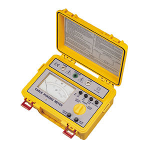
We hold one wire carefully with our fingers, and use the other for testing. If we hit a phase in the socket, the numbers on the indicator will be much greater than zero. When it hits zero, the screen will also show zero or an insignificant voltage value.
This device is convenient both because it is widely available on the radio measuring equipment market and because the measurements are made with fairly high accuracy.
Using an indicator screwdriver
It looks like a regular screwdriver, but with a slight difference. It has a transparent handle with a small light bulb inside. This, at first glance, is a rather primitive device, but in fact it is very convenient.
Simply insert it into the socket hole by touching the opposite end of the screwdriver with your finger. If there is a phase, the light bulb will light up. If there is a neutral wire or ground there, then it will not light up. It is important to remember that it is strictly forbidden to touch the metal part of the screwdriver during the measurement process. This may result in electric shock.
In some cases, the phase and neutral wire can be determined without any instruments or devices. This can be done if you read the label correctly. This is not a reliable method, but in some cases it may be useful.
When working in modern houses, the rules for such labeling are usually followed.
So, what are they:
- The wire where the phase is located, usually has a brown or black color.
- Null, Usually denoted by a blue wire.
- Green or yellow indicates the wire that serves for grounding.
These rules may have been different in previous time periods. Also, they may change in the future. Therefore, the described method is only suitable for preliminary testing of the purpose of the wires.
How to distinguish between grounding and neutral wire when the phase is disconnected?
Let us assume that there is no current in the network. Is there any difference in this case between ground and neutral wire? At first glance it may seem that they are very similar to each other.
In fact, their functions are still different. Grounding is intended for emergency situations. Through him electric charge goes into the ground. The neutral wire is part of the electrical circuit for power supply household electrical appliances in the house.
Here, the current, unlike grounding, is present. How can you tell them apart? When the phase is disconnected, you simply need to measure the current between this wire and a precisely known ground. If this is a neutral wire, then there will be a current, although small. If there is grounding, then there can be no current here.
In what cases might it be necessary?
With the huge variety of existing electrical appliances, there is a difference in which power supply they need. In different cases, such issues are resolved in different ways.
Sometimes, special devices are used for this - adapters. In some cases, it is simply necessary to connect it correctly to the outlet. In particular, when connecting electrical kitchen stove, when connecting, there is a need to correctly determine where the phase is in the socket and where the “working zero” is.
In this, and in similar cases, it is impossible to do without such information.
Another situation where this is necessary is a different kind of renovation work. When conducting them, you need to know exactly which wire is live (it must either be disconnected or reliably insulated) and which is not.
When connecting many household appliances, it really doesn’t matter which side the phase is on, but for a switch this may matter. Let us explain this. The “phase” should be supplied to the switch, and the “zero” should be connected directly to the lamps in the chandelier.
At the same time, during the process of replacing a lamp in a chandelier, with the switch turned off, a person will not receive an electric shock even if he accidentally touches it.
 (1 ratings, on average: 5,00 out of 5)

