How to make a Gauss cannon completely with your own hands. Game "Stalker", Gauss gun: where to find? Gauss gun. The simplest scheme
.
In this article, Konstantin, How-todo workshop, will show you how to make a portable Gauss cannon.
The project was done just for fun, so there was no goal to set any records in Gausso construction.


In fact, Konstantin even became too lazy to calculate the coil.


Let's first brush up on the theory. How does a Gauss gun actually work?
We charge the capacitor with high voltage and discharge it into a coil of copper wire located on the barrel.
When current flows through it, a powerful electromagnetic field is created. The ferromagnetic bullet is drawn into the barrel. The capacitor's charge is consumed very quickly and, ideally, the current through the coil stops flowing the moment the bullet is in the middle.

After which it continues to fly by inertia.
Before we move on to assembly, we should warn you that you need to work with high voltage very carefully.
Especially when using such large capacitors, this can be quite dangerous.

We will make a single-stage gun.
Firstly, because of the simplicity. The electronics in it are almost elementary.
When manufacturing a multi-stage system, you need to somehow switch the coils, calculate them, and install sensors.


Secondly, a multi-stage device simply would not fit into the intended pistol form factor.


Because even now the building is completely packed. Similar breaking pistols were taken as a basis.


We will print the body on a 3D printer. To do this, we start with the model.


We do it in Fusion360, all the files will be in the description if anyone wants to repeat it.

We will try to put all the details as compactly as possible. By the way, there are very few of them.
4 18650 batteries, giving a total of approximately 15V.
In their seat in the model there are recesses for installing jumpers.

Which we will make from thick foil.
A module that increases the battery voltage to approximately 400 volts to charge the capacitor.

The capacitor itself, and this is a 1000 uF 450 V bank.

And one last thing. Actually the coil.


Other little things such as a thyristor, batteries for opening it, start buttons can be placed in a canopy or glued to the wall.

So there are no separate seats for them.
For the barrel you will need a non-magnetic tube.

We will use the body of a ballpoint pen. This is much easier than printing it on a printer and then sanding it.

We wind varnished copper wire with a diameter of 0.8 mm onto the coil frame, laying insulation between each layer. Each layer must be firmly fixed.


We wind each layer as tightly as possible, turn to turn, making as many layers as will fit in the body.

The handle will be made of wood.


The model is ready, you can start the printer.

Almost all parts are made with a 0.8 mm nozzle and only the button that holds the barrel is made with a 0.4 mm nozzle.


The printing took about seven hours, so it turned out that only pink plastic remained.
After printing, carefully clean the model from supports. We buy primer and paint at the store.


Use acrylic paint It didn’t work out, but she refused to lay down normally even on the ground.
For painting PLA plastic, there are special sprays and paints that will adhere perfectly without preparation.
But such paints were not found, it turned out clumsily of course.
I had to paint halfway out of the window.


Let's say that uneven surface- this is such a style, and in general this is how it was planned.
While printing is in progress and the paint is drying, let's work on the handle.
There was no wood of suitable thickness, so we glued two pieces of parquet together.


When it's dry, we give it a rough shape using a jigsaw.


We will be a little surprised that the cordless jigsaw cuts 4cm of wood without any difficulties.

Next, use a Dremel and an attachment to round the corners.


Due to the small width of the workpiece, the tilt of the handle is not quite as desired.

Let's smooth out these inconveniences with ergonomics.

We rub over the unevenness with a sandpaper attachment and go over it manually with 400 grit.

After cleaning, coat with oil in several layers.


We attach the handle to the self-tapping screw, having previously drilled a channel.


Using finishing sandpaper and needle files, we adjust all the parts to each other so that everything closes, holds and clings as needed.


You can move on to electronics.
First of all, we install the button. Approximately estimating so that it will not interfere too much in the future.


Next, we assemble the battery compartment.
To do this, cut the foil into strips and glue it under the battery contacts. We connect the batteries in series.

We constantly check that the contact is reliable.
When this is done, you can connect the high-voltage module through the button, and a capacitor to it.


You can even try charging it.
We set the voltage to about 410 V; in order to discharge it to the coil without loud pops of closing contacts, you need to use a thyristor that works like a switch.

And for it to close, a small voltage of one and a half volts on the control electrode is enough.


Unfortunately, it turned out that the boost module has a middle point, and this does not allow taking the control voltage from already installed batteries without special tricks.
Therefore, we take a AA battery.


And the small tact button serves as a trigger, switching large currents through the thyristor.


It would all have ended there, but two thyristors could not withstand such abuse.
So I had to select a more powerful thyristor, 70TPS12, it can withstand 1200-1600V and 1100A per pulse.


Since the project has been frozen for a week anyway, we will also buy additional parts in order to make a charge indicator. It can operate in two modes, lighting only one diode, shifting it, or lighting all of them one by one.
For probably 50 years now, everyone has been saying that the age of gunpowder has come to an end, and firearms can no longer develop. Despite the fact that I absolutely disagree with this statement and believe that modern firearms, or rather cartridges, still have room to grow and improve, I cannot ignore attempts to replace gunpowder and, in general, the usual operating principle of weapons. It is clear that so far much of what has been invented is simply impossible, mainly due to the lack of a compact source electric current or because of the complexity of production and maintenance, but at the same time they lie on a dusty shelf and many interesting projects are waiting for their time.
Gauss gun
I would like to start with this particular sample for the reason that it is quite simple, and also because I have my own small experience in trying to create such a weapon, and, I must say, not the most unsuccessful one.
Personally, I first learned about this type of weapon not from the game “Stalker”, although it is thanks to it that millions know about this weapon, and not even from Fallout games, but from the literature, namely from the UT magazine. The Gauss cannon presented in the magazine was the most primitive and was positioned as a children's toy. So, the “weapon” itself consisted of a plastic tube with a coil wound on it copper wire, which played the role of an electromagnet when electric current was applied to it. A metal ball was placed into the tube, which, when current was applied, sought to attract an electromagnet. To prevent the ball from “hanging” in the electromagnet, the current supply was short-term, from an electrolytic capacitor. Thus, the ball accelerated to the electromagnet, and then, when the electromagnet was turned off, it flew on its own. An electronic target was proposed for all this, but let’s not get into the topic of what interesting, useful and, most importantly, popular literature used to be.
 Actually, the device described above is the simplest Gauss cannon, but it is natural that such a device clearly cannot be a weapon, unless it has a very large and powerful single electromagnet. To achieve acceptable projectile speeds, it is necessary to use, so to speak, a stepwise acceleration system, that is, several electromagnets must be installed on the barrel one after another. The main problem when creating such a device at home is the synchronization of the operation of electromagnets, since the speed of the projectile being thrown directly depends on this. Although straight hands, a soldering iron and an attic or cottage with old TVs, tape recorders, record players and no difficulties are not terrible. On this moment Having glanced over the sites where people demonstrate their creativity, I noticed that almost everyone places the coils of electromagnets on the barrel itself, roughly speaking, they simply wind the coils around it. Judging by the test results of such samples, such weapons are not far from the current publicly available pneumatics in terms of efficiency, but they are quite suitable for recreational shooting.
 Actually, what torments me most is why they are trying to place the coils on the barrel; it would be much more effective to use electromagnets with cores that would be directed by these same cores to the barrel. Thus, it is possible to place, say, 6 electromagnets in the area previously occupied by one electromagnet; accordingly, this will give a greater increase in the speed of the projectile being thrown. Several sections of such electromagnets along the entire length of the barrel will be able to accelerate a small piece of steel to decent speeds, although the installation will weigh a lot even without a current source. For some reason, everyone is trying and calculating the discharge time of the capacitor that powers the coil in order to coordinate the coils with each other so that they accelerate the projectile rather than slow it down. I agree, it’s a very interesting activity to sit down and consider; in general, physics and mathematics are wonderful sciences, but why not coordinate the coils using photos and LEDs and a simple circuit, it seems like there is no particular shortage and you can get the necessary parts for a reasonable fee, although, of course, you can count cheaper. Well, what about the power source? electrical network, transformer, diode bridge and several electrolytic capacitors connected in parallel. But even with such a monster weighing about 20 kilograms without an autonomous source of electric current, impressive results are unlikely to be achieved, although it depends on how impressionable one is. And no, no, I didn’t do anything like that (lowering my head, moving my foot in a slipper along the floor), I just made that toy from UT with one coil.
 In general, even when used as some kind of stationary weapon, say the same machine gun to protect an object that does not change its location, such a weapon will be quite expensive, and most importantly heavy and not the most effective, unless of course we are talking about reasonable dimensions and not about a monster with a five-meter trunk. On the other hand, a very high theoretical rate of fire and ammunition at a price of a penny per half ton look very attractive.
Thus, for a Gauss gun the main problem is that electromagnets have a lot of weight, and, as always, a source of electric current is required. In general, no one is developing weapons based on the Gauss gun; there is a project to launch small satellites, but it is rather theoretical and has not been developed for a long time. Interest in the Gauss gun is maintained only thanks to cinema and computer games, and also for enthusiasts who love to work with their heads and hands, of which, unfortunately, there are not so many in our time. For weapons, there is a more practical device that consumes electric current, although the practicality here can be argued, but unlike the Gauss gun, there are certain shifts.
RailGun or in our opinion Railgun
 This weapon is no less famous than the Gauss gun, for which we must say thanks to computer games and cinema, however, if everyone who is interested in this type of weapon is familiar with the principle of operation of the Gauss gun, then not everything is clear with the railgun. Let's try to figure out what kind of beast this is, how does it work and what are its prospects?
It all started back in 1920, it was in this year that a patent was received for this type of weapon, and initially, no one planned to use the invention for peaceful purposes. The author of the railgun, or the more famous railgun, is the Frenchman - Andre Louis-Octave Fauchon Vieple. Despite the fact that the designer managed to achieve some success in defeating enemy personnel, no one was interested in his invention, the design was very cumbersome, and the result was so-so and quite comparable to firearms. So for almost twenty years the invention was abandoned, until a country was found that could afford to spend huge amounts of money on the development of science, and especially that part of science that could kill. We are talking about Nazi Germany. It was there that Joachim Hansler became interested in the French invention. Under the leadership of the scientist, much more was created efficient installation, which had a length of only two meters, but accelerated the projectile to a speed of more than 1200 meters per second, although the projectile itself was made of aluminum alloy and weighed 10 grams. However, this was more than enough to fire at both enemy personnel and unarmored vehicles. In particular, the designer positioned his development as a means of combating air targets. More high speed the flight of a projectile, in comparison with a firearm, made the designer’s work very promising, since it was much easier to fire at moving, and constantly moving, targets. However, the design required improvement and the designer did a lot of work to improve this sample, slightly changing the initial principle of its operation.
 In the first sample, everything was more or less clear and there was nothing fantastic. There were two rails, which were the “barrel” of the weapon. The projectile itself was placed between them, which was made of a material that passed electric current; as a result, when current was applied to the rails, under the influence of the Lorentz force, the projectile rushed forward and in ideal conditions, which, naturally, would never be achieved, its speed could approach the speed of light. Since there were many factors that prevented the projectile from being accelerated to such speeds, the designer decided to get rid of some of them. The main achievement was that in the latest developments, the no longer thrown projectile closed the circuit, this was done by an electric arc behind the thrown projectile; in fact, this solution is still used today, only being improved. Thus, the designer managed to approach the flight speed of a thrown projectile equal to 3 kilometers per second, this was 1944 of the last century. Fortunately, the designer did not have enough time to complete his work and solve the problems that the weapon had, and there were quite a few of them. And so much so that this development was pushed to the Americans and no work was carried out in this direction in the Soviet Union. It was only in the seventies that we began to develop these weapons and at the moment we, unfortunately, are lagging behind, well, at least according to publicly available data. In the United States, they have long reached a speed of 7.5 kilometers per second and are not going to stop. Work is currently being carried out towards the development of the railgun as a means of air defense, so as a hand-held firearm, the railgun is still a fantasy or a very distant future.
 The main problem with the railgun is that to achieve maximum efficiency it must use rails with very low resistance. At the moment they are covered with silver, which seems to be not so expensive in financially, however, taking into account the fact that the “barrel” of the weapon is not one or two meters long, this is already a significant expense. In addition, after several shots, the rails need to be changed and restored, which costs money, and the rate of fire of such weapons remains very low. In addition, we should not forget that the rails themselves try to push away from each other under the influence of the same forces that accelerate the projectile. For this reason, the structure must have sufficient strength, but at the same time the rails themselves must be able to be quickly replaced. But this is not the main problem. A shot requires a huge amount of energy, so with one car battery You can’t get away with it behind your back; here you already need more powerful sources of electric current, which calls into question the mobility of such a system. So in the USA they are planning to install similar installations on destroyers, and they are already talking about automating the supply of projectiles, cooling and other delights of civilization. At the moment, the declared firing range for ground targets is 180 kilometers, but they are still silent about air targets. Our designers have not yet decided where they will apply their developments. However, from scraps of information we can conclude that the railgun will not be used as an independent weapon for now, but as a means that complements already existing long-range weapons, allowing you to significantly add the desired couple of hundred meters per second to the speed of the projectile being thrown, the railgun has good prospects, and the cost of such a development will be much lower than some megaguns on our own ships.
The only question that remains is whether we should be considered lagging behind in this matter, since usually what works poorly is tried to be promoted by everyone possible ways“Everyone was afraid of it,” but what is really effective, but its time has not yet come, is closed behind seven locks. Well, at least that's what I want to believe.
An electromagnetic rail rifle, commonly known as a Gauss gun, cannot be found in a weapons store. It does not leave cartridges and does not misfire, is silent, does not need to be cleaned, an ordinary nail can act as a cartridge for this electromagnetic rail gun, and the Gauss rifle works on the principle of alternating magnetic field, accelerating objects to mind-blowing speeds.
Since, unlike other weapons, you can find and buy electromagnetic gun Gauss is not allowed, here we will talk in detail about its circuit, operating principle and how to make this Gauss rail rifle at home with your own hands.
Attention! Having assembled an electromagnetic rifle or pistol with your own hands, do not forget to register your rail gun with the police and obtain permission to carry it or store it at home for self-defense, because like other weapons, the Gauss gun poses a mortal danger to you and the people around you, and Illegal possession of it is punishable by the criminal code!
How to make a homemade Gauss gun
To analyze in detail the principle of operation of a homemade Gauss rifle, let's first try to make a prototype of an electromagnetic rail gun from an ordinary ruler (a logarithmic one is best, so that by removing the middle from it, we get a groove for balls), 4 identical powerful magnets, a knife, adhesive tape and 9 metal balls with a diameter not exceeding the height of the magnets. Assembling a prototype rifle (let's call it a Gauss pistol) is as easy as shelling pears, even at home and with your own hands.
Tape the magnets to the ruler at equal distances from each other in the middle of the groove, making sure that the outer magnets are not too close to the ends of the ruler and charge 2 balls on one side of each magnet. To shoot, load the ball into the groove at the edge of the ruler on the side where there are no balls near the magnet and release. The magnetic field will attract it to the magnet, the ball will impart its energy to another ball through it, and due to the influence of this energy on it and, in addition, another magnetic field created by the next magnet in the circuit, it will accelerate it even faster, about 2 times.
OK it's all over Now! The prototype of a homemade Gauss gun was made at home with your own hands and, according to the principle of operation of the gun, is no different from the original, the Gauss rifle, we will now tell you how to assemble the diagram of which at home yourself.
How to make a Gauss gun
You can't assemble a Gauss rifle with just magnets and a ruler. Where to find starting materials for free? Most likely, you will have to at least spend money on several 400-450 Volt capacitors, the total capacity of which would be in the range of 1000-2000 mF, a copper wire with insulation with a diameter of 1 mm, a compartment for Krona type batteries and a pair of one and a half volt batteries, a trigger mechanism for your homemade Gauss rifle at home in the form of a button and a toggle switch, about 5 disposable cameras that have a flash, a couple of straws from some McDuck, in which you can also eat for free, a regular relay from a Zhiguli car on 4 contacts and some kind of housing for a Gauss gun in the form of a toy pistol, machine gun, etc., on which it will depend appearance your homemade electromagnetic Gauss rail gun, which can be made according to the following scheme:
The principle of Gauss weapons is also built on the electromagnetic properties of a gun; a dielectric barrel along with an iron charge is located inside an inductive coil, and when electricity is supplied to the solenoid, the resulting magnetic field gives the projectile considerable acceleration.
If you haven’t guessed yet, we need disposable cameras for the sake of a capacitor charging device, because we don’t want to make a disposable Gauss rifle? However, when disassembling a disposable camera, be extremely careful, never touch parts of the electrical circuit and close the capacitor output as quickly as possible using a screwdriver with a dielectric handle. Clean the charger from the battery clips, capacitor and solder a bridge to it to the contacts of the button to charge the future Gauss electromagnetic rail gun. Follow the above method with the remaining disposable cameras.
In order for the acceleration of a rail gun to be maximum, by the time the projectile reaches the solenoid (an inductive coil that does not have a core), the magnetic field must also be maximum, dropping sharply when the projectile is close to the solenoid, for this it is necessary to coordinate the characteristics of the capacitors, the projectile and coils of the future homemade Gauss rifle.
To make a solenoid for a Gauss gun, assemble together 4 cm of straw, two washers big size from plastic or cardboard, assembling a bobbin using a nut and screw. Wind the copper wire, carefully making sure that the wire is not bent anywhere and that the insulation is not inadvertently damaged; before winding the next layer, and there should be ten of them in total, fill the previous one with superglue. Disassemble the structure and insert a long straw into the solenoid, which will become the barrel of an electromagnetic Gauss rail rifle with your own hands at home. You can check the functionality of the resulting part using a regular 9V battery and a paper clip.
Having assembled a Gauss gun according to the circuit, before firing, monitor the LEDs to determine the moment when the voltage of the capacitors has increased to the 330V we need, usually this takes up to a minute, but if you connect several 3V batteries in parallel to charging the capacitors so that each 3V compartment is connected in parallel all charges so that the charging boards do not burn out, then the reloading time for a homemade Gauss rifle assembled at home can be significantly reduced.
To ensure the safety of a ready-made Gauss electromagnetic rail gun made with your own hands at home as trigger mechanism use a relay so as not to contact the button that discharges the capacitors directly. A high-voltage circuit can only be assembled with a wire with a diameter of at least 1 mm, and the capacitors must be additionally discharged, arranging short circuit, so that the Gauss cannon can be safely stored at home after firing.
To fire from a homemade Gauss rifle, turn on the power, wait for a signal from the LEDs, load the projectile so that it is slightly behind the solenoid, turn off the power and shoot. An electromagnetic rail weapon made using this method is amazing in its power and should under no circumstances be aimed at living people.
If you don’t understand anything about this, then it would be better to start by studying
Information is provided for educational purposes only!
The site administrator is not responsible for possible consequences use of the information provided.
CHARGED CAPACITORS DEADLY DANGEROUS!
Electromagnetic gun (Gauss gun, English. coilgun) in her classic version is a device that uses the property of ferromagnetic materials to be drawn into a region of a stronger magnetic field to accelerate a ferromagnetic “projectile”.
My gauss gun:
view from above: 
side view: 
1 - connector for connecting a remote release
2 - “battery charge/work” switch
3 - connector for connecting to a computer sound card
4 - capacitor charge/shot switch
5 - emergency capacitor discharge button
6 - "Battery charge" indicator
7 - "Work" indicator
8 - "Charge of capacitor" indicator
9 - "Shot" indicator
Diagram of the power part of the Gauss gun:

1 - trunk
2 - protective diode
3 - coil
4 - IR LEDs
5 - IR phototransistors
The main design elements of my electromagnetic gun:
battery
-
I use two lithium ion battery SANYO UR18650A 18650 format from a laptop with a capacity of 2150 mAh, connected in series:
...
The maximum discharge voltage of these batteries is 3.0 V.
voltage converter for powering control circuits -
The voltage from the batteries is supplied to a step-up voltage converter on the 34063 chip, which increases the voltage to 14 V. Then the voltage is supplied to the converter to charge the capacitor, and stabilized to 5 V by the 7805 chip to power the control circuit.
voltage converter for charging the capacitor
-
boost converter based on 7555 timer and MOSFET-transistor ;
- This N-channel MOSFET- transistor in housing TO-247 with the maximum permissible drain-source voltage VDS= 500 volts, maximum pulsed drain current I D= 56 amperes and typical open-state drain-to-source resistance RDS(on)= 0.33 ohm. 
The inductance of the converter choke affects its operation:
too low inductance determines low speed capacitor charge;
too high an inductance can lead to core saturation.
As a pulse generator ( oscillator circuit) for converter ( boost converter) you can use a microcontroller (for example, the popular Arduino), which will allow implementing pulse width modulation (PWM, PWM) to control the duty cycle of pulses.
capacitor (coil cap(acitor)) -
electrolytic capacitor for a voltage of several hundred volts.
Previously, I used a K50-17 capacitor from a Soviet external flash with a capacity of 800 μF for a voltage of 300 V: 
The disadvantages of this capacitor are, in my opinion, the low operating voltage, increased leakage current (leads to longer charging) and possibly increased capacitance.
Therefore, I switched to using imported modern capacitors: 
SAMWHA for voltage 450 V with a capacity of 220 μF series HC. HC- this is a standard series of capacitors SAMWHA, there are other series: HE- working in a broader temperature range, H.J.- with increased lifetime;
PEC for a voltage of 400 V with a capacity of 150 μF.
I also tested a third capacitor for a voltage of 400 V with a capacity of 680 μF, purchased from an online store dx.com -
In the end I settled on using a capacitor PEC for a voltage of 400 V with a capacity of 150 μF.
For a capacitor, its equivalent series resistance ( ESR).
switch -
power switch S.A. designed for switching a charged capacitor C per reel L:
either thyristors or IGBT-transistors:
thyristor
-
I use power thyristor ТЧ125-9-364 with cathode control
appearance
dimensions  - high-speed pin thyristor: “125” means the maximum permissible effective current(125 A); "9" means the class of the thyristor, i.e. repetitive pulse voltage in hundreds of volts (900 V).
Using a thyristor as a key requires selecting the capacitance of the capacitor bank, since a prolonged current pulse will lead to the retraction of a projectile that has passed the center of the coil back - " suck-back effect".
IGBT transistor -
use as a key IGBT-transistor allows not only to close, but also to open the coil circuit. This allows the current (and the coil's magnetic field) to be interrupted after the projectile passes through the center of the coil, otherwise the projectile would be pulled back into the coil and therefore slow down. But opening the coil circuit (a sharp decrease in the current in the coil) leads to the appearance of a pulse high voltage on the coil in accordance with the law of electromagnetic induction $u_L = (L ((di_L) \over (dt)) )$. To protect the key -IGBT-transistor, additional elements must be used: 
VD TVs- diode ( TVS diode), creating a path for the current in the coil when the key is opened and dampening a sharp voltage surge on the coil
Rdis- discharge resistor ( discharge resistor) - provides attenuation of the current in the coil (absorbs the energy of the magnetic field of the coil)
C rsringing suppression capacitor), preventing the occurrence of overvoltage pulses on the key (can be supplemented with a resistor, forming RC-snubber)
I used IGBT-transistor IRG48BC40F from the popular series IRG4.
coil -
the coil is wound on plastic frame copper wire. The ohmic resistance of the coil is 6.7 ohms. The width of multilayer winding (pile) $b$ is 14 mm, there are about 30 turns in one layer, the maximum radius is about 12 mm, the minimum radius $D$ is about 8 mm (average radius $a$ is about 10 mm, height $c $ - about 4 mm), wire diameter - about 0.25 mm.
A diode is connected in parallel to the coil UF5408 (suppression diode) (peak current 150 A, peak reverse voltage 1000 V), dampening the self-induction voltage pulse when the current in the coil is interrupted.
barrel
-
Made from the body of a ballpoint pen.
projectile -
The parameters of the test projectile are a piece of nail with a diameter of 4 mm (barrel diameter ~ 6 mm) and a length of 2 cm (the volume of the projectile is 0.256 cm 3 and the mass $m$ = 2 grams, if we take the steel density to be 7.8 g/cm 3 ). I calculated the mass by imagining the projectile as a combination of a cone and a cylinder. 
The projectile material must be ferromagnetic.
Also, the projectile material should have as much high magnetic saturation threshold - saturation induction value $B_s$. One of best options is ordinary soft magnetic iron (for example, ordinary non-hardened steel St. 3 - St. 10) with a saturation induction of 1.6 - 1.7 Tesla. Nails are made from low-carbon, thermally untreated steel wire(steel grades St. 1 KP, St. 2 KP, St. 3 PS, St. 3 KP).
Steel designation:
Art.- carbon steel of ordinary quality;
0 - 10
- percentage of carbon increased by 10 times. As the carbon content increases, the saturation induction $B_s$ decreases.
And the most effective is the alloy " permendur", but it is too exotic and expensive. This alloy consists of 30-50% cobalt, 1.5-2% vanadium and the rest is iron. Permendur has the highest saturation induction $B_s$ of all known ferromagnets up to 2.43 Tesla.
It is also desirable that the projectile material has as much low conductivity. This is due to the fact that eddy currents arising in an alternating magnetic field in the conducting rod lead to energy losses.
Therefore, as an alternative to nail cutting projectiles, I tested a ferrite rod ( ferrite rod), taken from the inductor from the motherboard: 
Similar coils are also found in computer power supplies: 
Appearance of a ferrite core coil: 
Rod material (probably nickel-zinc ( Ni-Zn) (analogue of domestic brands of ferrite NN/VN) ferrite powder) is dielectric, which eliminates the occurrence of eddy currents. But the disadvantage of ferrite is the low saturation induction $B_s$ ~ 0.3 Tesla.
The length of the rod was 2 cm: 
The density of nickel-zinc ferrites is $\rho$ = 4.0 ... 4.9 g/cm 3 .
Projectile gravity
The calculation of the force acting on a projectile in a Gauss gun is complex task.
Several examples of calculating electromagnetic forces can be given.
The force of attraction of a piece of ferromagnet to a solenoid coil with a ferromagnetic core (for example, a relay armature to a coil) is determined by the expression $F = (((((w I))^2) \mu_0 S) \over (2 ((\delta)^ 2)))$, where $w$ is the number of turns in the coil, $I$ is the current in the coil winding, $S$ is the cross-sectional area of the coil core, $\delta$ is the distance from the coil core to the attracted piece. In this case, we neglect the magnetic resistance of ferromagnets in the magnetic circuit.
The force drawing a ferromagnet into the magnetic field of a coreless coil is given by $F = ((w I) \over 2) ((d\Phi) \over (dx))$.
In this formula, $((d\Phi) \over (dx))$ is the rate of change of the magnetic flux of the coil $\Phi$ when moving a piece of ferromagnet along the axis of the coil (changing the coordinate $x$), this value is quite difficult to calculate. The above formula can be rewritten as $F = (((I)^2) \over 2) ((dL) \over (dx))$, where $((dL) \over (dx))$ is the rate of change coil inductance $L$.
The procedure for firing a shot from a gauss gun
Before firing, the capacitor must be charged to a voltage of 400 V. To do this, turn on the switch (2) and move the switch (4) to the “CHARGE” position. To indicate voltage, a level indicator from a Soviet tape recorder is connected to the capacitor through a voltage divider. For emergency discharge of the capacitor without connecting the coil, a 6.8 kOhm resistor with a power of 2 W is used, connected using a switch (5) to the capacitor. Before firing, you must move the switch (4) to the “SHOT” position. To avoid the influence of contact bounce on the formation of a control pulse, the “Shot” button is connected to the anti-bounce circuit on the switching relay and microcircuit 74HC00N. From the output of this circuit, the signal triggers a one-shot device, which produces a single pulse of adjustable duration. This pulse arrives through an optocoupler PC817 on primary winding a pulse transformer that provides galvanic isolation of the control circuit from the power circuit. The impulse generated by secondary winding, opens the thyristor and the capacitor is discharged through it to the coil.
The current flowing through the coil during discharge creates a magnetic field that draws in the ferromagnetic projectile and imparts a certain initial speed to the projectile. After leaving the barrel, the projectile continues to fly by inertia. It should be taken into account that after the projectile passes through the center of the coil, the magnetic field will slow down the projectile, so the current pulse in the coil should not be prolonged, otherwise this will lead to a decrease in the initial speed of the projectile.
For remote control a button is connected to the connector (1): 
Determining the speed at which a projectile leaves the barrel
When fired, muzzle velocity and energy are highly dependent from the initial position of the projectile in the trunk.
To set the optimal position, it is necessary to measure the speed at which the projectile leaves the barrel. For this I used an optical speed meter - two optical sensor(IR LEDs VD1, VD2+ IR phototransistors VT1, VT2) are placed in the trunk at a distance of $l$ = 1 cm from each other. When flying, the projectile covers the phototransistors from the radiation of the LEDs, and the comparators on the chip LM358N generate a digital signal: 

When overlapping luminous flux sensor 2 (closest to the coil) lights up red (" RED") LED, and when sensor 1 is blocked - green (" GREEN").
This signal is converted to a level of tenths of a volt (dividers from resistors R1,R3 And R2,R4) and is fed to two channels of linear (not microphone!) input sound card computer using a cable with two plugs - a plug connected to the Gaussian connector, and a plug plugged into the computer's sound card socket:
voltage divider:
LEFT- left channel; RIGHT- right channel; GND- "Earth"
plug connected to the gun:
5 - left channel; 1 - right channel; 3 - "ground"
plug connected to the computer:
1 - left channel; 2 - right channel; 3 - "ground"
It is convenient to use for signal processing free program Audacity().
Since on each sound card input channel a capacitor is connected in series with the rest of the circuit, the sound card input is actually R.C.-chain, and the signal recorded by the computer has a smoothed form: 
Characteristic points on the graphs:
1 - flight of the front part of the projectile past sensor 1
2 - flight of the front part of the projectile past sensor 2
3 - flight of the rear part of the projectile past sensor 1
4 - flight of the rear part of the projectile past sensor 2
I determine the initial velocity of the projectile by the time difference between points 3 and 4, taking into account that the distance between the sensors is 1 cm.
In the given example, with a digitizing frequency $f$ = 192000 Hz for the number of samples $N$ = 160, the projectile speed $v = ((l f) \over (N)) = ((1920) \over 160)$ was 12 m/s .
The speed of a projectile leaving the barrel depends on its initial position in the barrel, specified by the displacement of the rear part of the projectile from the edge of the barrel $\Delta$: 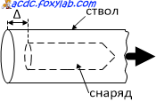
For each battery capacity $C$, the optimal projectile position ($\Delta$ value) is different.
For the projectile described above and a battery capacity of 370 uF, I got the following results:
With a battery capacity of 150 µF the results were as follows:
The maximum projectile speed was $v$ = 21.1 m/s (at $\Delta$ = 10 mm), which corresponds to an energy of ~ 0.5 J
-
When testing a ferrite rod projectile, it turned out that it requires a much deeper location in the barrel (a much larger $\Delta$ value).
Gun laws
In the Republic of Belarus, products with muzzle energy ( muzzle energy) no more than 3 J
purchased without appropriate permission and are not registered.
IN Russian Federation products with muzzle energy less than 3 J
are not considered weapons.
In the UK, products with muzzle energy are not considered weapons. no more than 1.3 J.
Determination of capacitor discharge current
To determine the maximum discharge current of a capacitor, you can use a graph of the voltage across the capacitor during discharge. To do this, you can connect to a connector to which the voltage on the capacitor, reduced by $n$ = 100 times, is supplied through a divider. Capacitor discharge current $i = (n) \cdot (C \cdot ((du) \over (dt))) = (((m_u) \over (m_t)) C tg \alpha)$, where $\alpha$ - the angle of inclination of the tangent to the capacitor voltage curve at a given point.
Here is an example of such a discharge voltage curve on a capacitor: 
In this example $C$ = 800 µF, $m_u$ = 1 V/div, $m_t$ = 6.4 ms/div, $\alpha$ = -69.4°, $tg\alpha = -2 .66 $, which corresponds to the current at the beginning of the discharge $i = (100) \cdot (800) \cdot (10^(-6)) \cdot (1 \over (6.4 \cdot (10^(-3) ))) \cdot (-2.66) = -33.3$ amperes.
To be continued
Hello. Today we will build a Gauss cannon at home using parts that can easily be found in local stores. Using capacitors, a switch and a few other parts, we will create a launcher that can use electromagnetism to launch small nails up to a distance of about 3 meters. Let's get started!
Step 1: Watch the video
Watch the video first. You will study the project and see the gun in action. Read on to explore more detailed instructions assembly of the Gauss Gun device.
Step 2: Gathering the necessary materials

For the project you will need:
- 8 large capacitors. I used 3,300uF 40V. The key point The point here is that the lower the voltage, the less danger, so look for options in the region of 30 - 50 Volts. As for capacity, the more the better.
- One high current circuit breaker
- One coil of 20 turns (I twisted mine from 18awg wire)
- Copper sheet and/or thick copper wire
Step 3: Glue the capacitors together

Take the capacitors and glue them together so that the positive terminals are closer to the center of the glue. First glue them into 4 groups of 2 pieces. Then glue two groups together, resulting in 2 groups of 4 capacitors. Then place one group on top of the other.
Step 4: Assembling a group of capacitors

The photo shows what the final design should look like.
Now take the positive terminals and connect them to each other and then solder them to the copper pad. The overlay can serve as a thick copper wire or leaf.
Step 5: Solder the copper pads

Use directed heat if necessary (slight industrial dryer), heat the copper strips and solder the capacitor terminals to them.
The photo shows my group of capacitors after completing this step.
Step 6: Solder the Negative Terminals of the Capacitors

Take another thick conductor, I used an insulated copper lead with a large cross-section, removing it in in the right places isolation.
Bend the wire so that it covers the entire distance of our group of capacitors as efficiently as possible.
Solder it in the right places.
Step 7: Prepare the projectile

Next you need to prepare a suitable projectile for the reel. I wound my reel around the bobbin. I used a small straw as a muzzle. Therefore, my projectile must fit into the straw. I took the nail and cut it to about 3cm long, leaving the sharp part.
Step 8: Find a suitable switch

I then needed to find a way to dump the charge from the capacitors onto the coil. Most people use rectifiers (SCRs) for such needs. I decided to take a simpler approach and found a switch that worked when high strength current
There are three current ratings on the switch: 14.2A, 15A, and 500A. My calculations showed a maximum force of about 40A at a peak lasting about a millisecond, so it should have worked.
THE NOTE. Do not use my switching method if your capacitors are larger. I pushed my luck and it all worked out fine, but you don't want a breaker to blow because you ran 300A through a breaker rated for 1A.
Step 9: Winding the Reel

We are almost finished assembling the electromagnetic gun. Time to wind the reel.
I tried three different coils and found that about 20 turns insulated wire 16 or 18 awg standards work best. I used an old bobbin, wrapped some wire around it and threaded a plastic straw through it, sealing one end of the straw with hot glue.
Step 10: Assembling the device according to the diagram


Now that you have all the pieces ready, put them together. If you have any problems, follow the diagram.
Step 11: Fire Safety


Congratulations! We made the Grasse cannon with our own hands. Use a charger to charge your capacitors to near maximum voltage. I charged my 40V setup to 38V.
Load the projectile into the tube and press the button. The current will flow to the coil and it will shoot a nail.
BE CAREFUL! Even considering that this is a low-current project and that it will not kill you, such current can still harm your health. The second photo shows what happens if you accidentally connect plus and minus.
 (1 ratings, on average: 5,00 out of 5)

