Grounded neutral system. Earthing systems for electrical installations
- diversion of voltage that has arisen in a place threatening safety to a place where it will not harm anyone: this place is earth. Grounding connects all current-carrying parts, which in normal operation are not under U, to the ground.
Zeroing - this is the connection of all parts of the electrical appliance that should not be under U, with a working zero. In this case, if a phase break occurs on the current-carrying parts that are under the working zero, then a short circuit will occur and circuit breaker de-energize the electrical appliance. This is of course less safe than grounding, a short circuit can cause subsequent malfunctions in the device. Unfortunately, it is zeroing that is the main type of protection in most residential premises.
Grounding systems
Consider the systems used in domestic premises:
TN-C
The first letter T means that the neutral of the power supply is connected to the ground, which means that the conductor of the working zero at the substation goes into the ground. The second letter - N - means the connection of open conductive parts of the electrical installation of the building with the grounding point of the power source. The third letter - C - means that the protective and working zero are on the same common PEN, that is, the working zero is protective. In fact, this system is the very “zeroing”. The most insecure of the systems. All current-carrying parts that should not be under U are under operating zero. Protection is built on the action of the automaton after short circuit. Protective and working zero are in the same conductor to the switchboard. 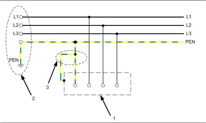
Fig 1 TN-C system
1 - exposed conductive parts.
2- power supply
3- switchboard for the apartment.
TN-S
The first two letters, as in the previous system, mean that the neutral of the power supply is connected to ground (which is located at the power source) and the exposed conductive parts of the electrical installation of the building are connected to the ground point of the power supply. The third letter - S - means that zero and protective PE and working N are on different conductors (grounding). This means that two individual wires to working zero and to ground. This system is the safest for multi-storey buildings.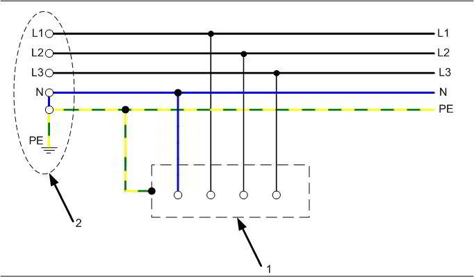
Fig 2 TN-S system
2-power supply
The presented diagram shows that two separate wires go from the power source to the working zero and to ground, then the conductors do not meet.
TN-C-S
It is an upgraded TN-C system. The functions of the zero working and zero protective conductors are combined in one conductor in the part of the network that comes from the power source. Then, a grounded conductor is added in a certain area. For multi-storey buildings usually a grounded conductor is added to the ASU (introductory Switchgear on house). This system also provides sufficient security. 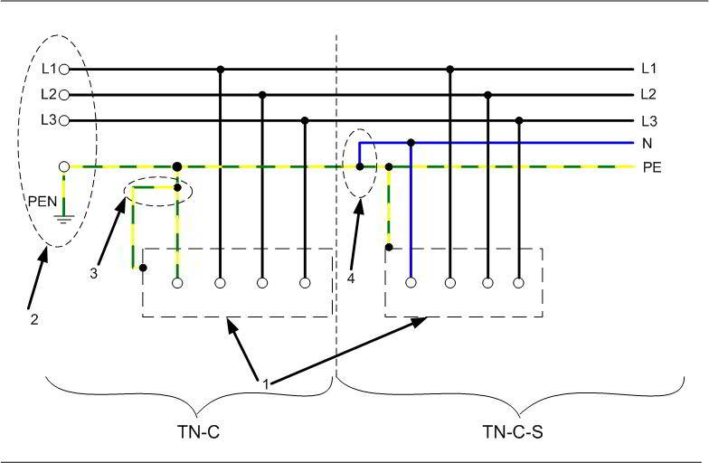
Fig 3 TN-C-S system
1-exposed conductive parts
2-power supply
3-Switchboard for the apartment
The diagram shows the network before modernization - TN-C system and after modernization - TN-C-S system.
TT system
Usually used in the construction of private houses. The second letter T means that grounding and working zero are not connected anywhere. The first letter has already been mentioned above. Three wires enter the house in the same way as in the TN-S system: working zero, phase wire and grounding. Only now the ground wire does not come from a power source (as in the TN-S system), but near a private house, its own ground loop is installed in accordance with all the rules of the PUE (electrical installation rules), it is from the ground loop that the ground wire comes.
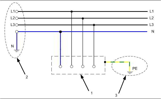
Fig 4 TT system
1-exposed conductive parts
2-power supply
3-ground loop near a private house and a conductor extending from it.
The most perfect, for today, grounding system "TN-S"(type of electrical network) strongly recommended for use by the PUE (Electrical Installation Rules). In Russia, a system similar to TN-C is still used (TN-C system is prohibited in new construction, in single-phase and direct current. This requirement does not apply to branches from overhead lines with voltage up to 1 kV to single-phase consumers of electricity - PUE 1.7.132).
Grounding system "TN-S"- from supply substations to the consumer go two different zero wires: N - working zero and PE - protective zero Thus, the greatest electrical safety is ensured, both for humans and for electrical consumers.
In the event of a breakdown to the case, the leakage current flows through the grounding (grounding) conductor to the protective zero - PE, which causes a trip RCD(currents through the differential transformer to the load and back are not equal). And with a large leakage current, it works circuit breaker
In general, the "TN-S" grounding system was first developed in the 1930s and introduced on the territory of European countries, in which recent years 50 is the main scheme for protecting electricity consumers. Most likely, the same task is facing the Russian enterprises of electrical networks, since when designing new power supply development lines, it is recommended to use a five-core electrical installation For three-phase inputs and three-wire - for single-phase connection, starting from the power source and ending with the outlet of a particular subscriber. As you know, recommendations very often turn into norms and provisions of standards, but for now one of the stages of such a transition is mandatory electrical installation according to the system grounding TN-С-S, since the direct transition from TN-С to TN-S involves large capital investments and is comparable to the construction of a new hydroelectric power station.
Fig1. TN-C system
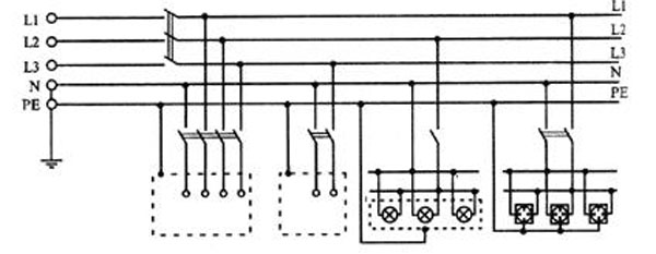
Fig2. TN-S system
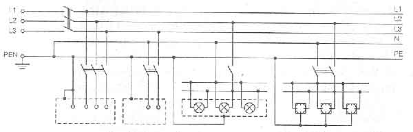
Fig3. TN-C-S system
What is so remarkable about it, if it is required, albeit a gradual, but mandatory transition? To find out, let's first look at it. wiring diagram. It is completely identical to the traditional power supply system, where, in addition to current-carrying lines, a neutral conductor is included, with the important difference that another neutral conductor is added to the circuit, which does not require re-grounding either on the “N” line or on the “PE” line, which is carried out only on the initial power source. Thus, allowing them to separate their workers and protective functions on separate power rails. That is, the working conductor "N" performs only the functions of the EMF ( electromotive force - physical quantity characterizing the work of external (non-potential) forces in sources of constant or alternating current. In a closed conducting circuit, the EMF is equal to the work of these forces in moving a single positive charge along the circuit), and the “PE” conductor is only a protection function, while achieving complete isolation from each other. Such a wiring diagram is especially relevant in the context of problems when there is absolutely no control over the state of protective grounded circuits, as you can see, the need for this is completely eliminated.
Now, after we figured out the electrical circuit, it becomes obvious that such a "TN-S" grounding system provides maximum protection electrical equipment and the person himself. Moreover, it eliminates high-frequency pickups and other interference on consumer lines coming from some devices. Each of us must have observed a similar situation when, in next door someone used an electric razor, sometimes a drill or welding machine, rattling distortion appeared on the TV screen. Such a system, if not completely, then most interference, oscillatory and electromagnetic excitations that sometimes occur in electrical networks, certainly excludes. Therefore, the TN-S grounding system is very fond of employees who work with information, telecommunications, radar or location equipment, since maximum isolation from casings and cases of other electrical devices, as well as pickups through the "ground", in other words, from interference sources.
Conventions grounding systems:
First letter is the state of the source neutral with respect to earth.
T- grounded neutral.
I- isolated neutral.
Second letter- state of exposed conductive parts relative to earth.
T- exposed conductive parts are earthed regardless of the relation to earth of the neutral of the power supply or any point of the supply network.
N- exposed conductive parts are connected to a dead-earthed neutral of the power source.
Letters after N- combination in one conductor or separation of the functions of the zero working and zero protective conductors.
S- zero working (N) and zero protective (PE) conductors are separated.
WITH- the functions of the zero protective and zero working conductors are combined in one conductor (PEN-conductor).
Power supply systems are classified by the International Electrotechnical Commission (IEC) depending on the method of grounding the distribution network and the applied protection measures against damage. electric shock. Distribution networks are divided into networks with grounded neutral and networks with isolated neutral. The IEC-364 standard subdivides distribution networks depending on the configuration of current-carrying conductors, including the zero working (neutral) conductor, and the types of earthing systems. In this case, the following notation is used. The first letter, I or T, characterizes the connection with the earth of current-carrying conductors (grounding of the network). The second letter, T or N, characterizes the connection to the ground of open conductive parts (HFC) and third-party conductive parts (HFC) (equipment grounding).
First letter (I or T) The first letter I means that all current-carrying parts are isolated from the ground, or - that one point of the network is connected to the ground through a resistance or - through a spark gap or - an air gap. Isolated neutral (I) networks can be: (1) very small networks, such as safety extra-low voltage (SELV or SELV) networks with electrical separation by isolating transformers, or (2) medium-sized networks, such as those used to supply individual shops, or (3) distribution networks to supply entire areas of a city, such as three-phase 230 V networks (IT system). In recent years, the IT system was commonly used in Europe, but then it was replaced almost everywhere by systems with earthed neutral.
There are several reasons for this substitution. One such reason is surge protection. Only in Norway is the IT system still widely used. The isolated neutral system is gradually being replaced three-phase system 230/400 V with earthed neutral. Everywhere in the world, the use of the IT system is limited to special applications in those industries where a power outage can be dangerous. For example, to power explosive industries.
The first letter T indicates a direct connection, at least one point of the network, with the earth (terra). For example, powered by secondary winding star-connected transformer, three-phase distribution network with a neutral conductor, voltage 127/220 V or 220/380 V with a neutral connected to earth through an earthing device.
Special requirements, imposed on grounding devices, depending on the type of networks, will be discussed in subsequent chapters.
Second letter (T or N) The second letter indicates the type of connection between the HRE, the protective earth conductor (equipment earth) of the installation, and earth. The second letter T means a direct connection between the HRE and HFC and ground (terra), independent of the system ground, which may or may not contain current-carrying parts of the system. The second letter N means a direct connection of the HRE and HFC with a grounded point (points) of the network using a PEN or PE conductor. Mains grounding and protection against electric shock are each subject to independent review.
Network (working) and protective grounding
| System designation | Mains ground |
Protective earth conductive parts |
There is no direct connection to earth. It is allowed to connect to earth through resistance, air gap, arrester, etc. |
||
Ground connection at one or more points of the distribution network outside the customer's network |
Direct connection to earth, independent of mains earth |
|
Connection to earth at one or more points in the distribution network and at one or more points in the consumer network |
Connection to mains earth with PE or PEN conductor |
|
Ground connection at one or more distribution network points |
No connections to earth or mains earth |
Current-carrying parts of the network are connected to earth to limit the voltage that may appear on them as a result of a direct lightning strike (CLS) or secondary manifestations of lightning (induced overvoltage waves), or as a result of unintentional contact with higher voltage lines, or as a result of insulation breakdown of current-carrying parts of the distribution network.
The reasons why the current-carrying parts of the distribution network are not connected to the ground are as follows: in order to avoid interruption of the consumer's power supply with a single damage (insulation breakdown to the ground of the current-carrying strips of the distribution network); in order to avoid sparking in explosive and fire hazardous areas with a single damage to the insulation of current-carrying parts of the network. Grounding of electrical equipment, more specifically, grounding of exposed conductive parts (HPC), is one of the many measures that can be used to protect against electric shock. Grounding HRE involves the creation of an equipotential environment, which reduces the likelihood of voltage on the human body. In a TN system, the HRE grounding provides a low resistance circuit for the fault current. This facilitates the operation of overcurrent protection devices.
The designations TN, TT and IT refer only to the distribution network configuration. These designations are limited to various methods, which can be used to provide protection against electric shock, including grounding the HRE. Although each system is provided by connecting the HRE to earth, effective method used in an installation for protection against electric shock may include other protective measures such as double insulation.
The configuration of the distribution network and the measures used to protect against electric shock are each subject to independent consideration.
On fig. 1. - 5. systems are given three-phase networks. The designations used in the figures have the following meaning:
T - direct connection of one point of the current-carrying parts of the power source to the ground,
I - all current-carrying parts are isolated from the ground, or one point is grounded through resistance.
The second letter is the nature of the grounding of open conductive parts (HFC) of the electrical installation:
T - direct connection of the HRE with the earth, regardless of the nature of the connection between the source of the litany and the earth,
N - direct connection of the HRE with the grounding point of the power supply (usually grounded with neutral in AC systems).
The subsequent letters (if any) are the device of the zero working and zero protective conductor.
S - the function of the zero protective and zero working conductor is provided by separate conductors.
C - the functions of the zero protective and zero working conductors are combined in one conductor (PEN-conductor).
TN system
The supply networks of the TN system have a point directly connected to the ground. The open conductive parts of the electrical installation are connected to this point by means of zero protective conductors.
Depending on the device of the zero working and zero protective conductors, the following three types of TN systems are distinguished:
TN-S system - zero operating and zero protective conductors operate separately throughout the system.
Rice. 1. TN-S system (zero working and zero protective conductors work separately) 1 - grounding of the power supply; 2 - exposed conductive parts
TN-C-S system - the functions of the zero working and zero protective conductors are combined in one conductor in the network part. 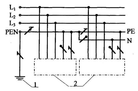
Rice. 2. TN-C-S system (in the part of the network, the zero working and zero protective conductors are combined) 1 - grounding of the power source; 2 - exposed conductive parts
TN-C system - the functions of the zero working and zero protective conductors are combined in one conductor throughout the network. 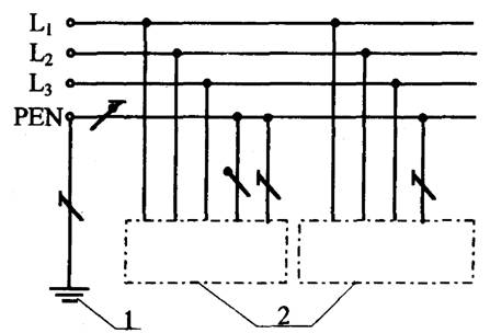
Rice. 3. TN-C system (zero working and zero protective conductors are combined throughout the network) 1 - power supply grounding; 2 - exposed conductive parts
TT system
The supply network of the TT system has a point directly connected to earth, and the exposed conductive parts of the electrical installation are connected to an earth electrode electrically independent of the earth electrode of the power supply neutral. 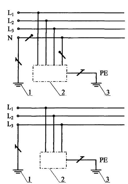
Rice. 4. TT system
1 - power supply grounding; 2 - open conductive parts; 3 - grounding of equipment cases
IT system
The supply network of the IT system does not have a direct connection of current-carrying parts to the ground, and the exposed conductive parts of the electrical installation are grounded. 
Rice. 5. IT system
1 - resistance; 2 - power supply grounding; 3 - open conductive parts; 4 - grounding of equipment cases
 (1 ratings, on average: 5,00 out of 5)

