Sealing the ends of the wires. Dry cable termination
Saturday, March 10, 2012 10:00:00
Cable terminations
IN distribution devices used for terminating cables at their connection points Various types end seals.
End seals for power cables with paper and plastic insulation must be carried out in accordance with the technical documentation.
Dry end seals with polyvinyl chloride tapes, as well as end seals in the form of rubber gloves, cannot be used in wet and damp rooms, which include substations of city networks and complete transformer substations outdoor installation
To terminate cables with voltages of 1 - 10 kV, KVE terminations with a housing made of epoxy compound are used, which are easy to install and fire safe.
End seal KVED
End internal epoxy seal KVED with two-layer tubes. The distance between the tubes at the exit of the cores from the epoxy casing for cables for a voltage of 10 kV must be at least 25 mm. In the KVED termination, two-layer tubes are put on the core insulation, the outer layer of which is made of polyethylene, and the inner layer is made of polyvinyl chloride.
To increase the tightness of the root, the cutting is filled with epoxy compound. To avoid the penetration of the impregnating composition of the cable insulation between the layers of the tube, make a step (cut off the top polyethylene layer) at a distance of at least 20 mm, and treat the area special glue PED-B, having good adhesion(adhesion) to epoxy. This glue is used to lubricate inner surface At the upper end of the tube, which is put on the tip, a bandage of twisted twine is placed on top of the tube in this place. The installed seal is painted with special enamel.
End seal KVEN
The end seal KVEn differs from KVED in that instead of two-layer tubes, tubes made of nayrite rubber are used to seal the insulation of the cores. These tubes provide poorer insulation protection against moisture than double-layer tubes and should therefore not be used in damp areas.
End seal KVB
End seals for internal installation in KVB steel funnels (internal bitumen end seals) are widely used. Steel funnels of end seals can have an oval or round shape. In these end seals, 3-4 layers of insulating tape (adhesive polyvinyl chloride or varnished fabric with varnish gluing) are wound over the insulation of the cable cores with a 50% overlap, and a conical winding is made in the place where the porcelain bushings are installed for a tight fit. In order to prevent the bituminous mass from leaking out, a winding of resin tape is made at the neck of the funnel. The funnel and cable cores are painted with enamel. For voltages up to 1 kV, end seals are installed without porcelain bushings and covers.
Repair of cable terminations
When repairing power cable terminations, it is usually performed during current repairs substation equipment. When repairing power cable terminations, check that the distances from phases to ground comply with the values specified in the PUE. At a voltage of 6 kV this distance must be at least 90 mm, at 10 kV - 120 mm.
The surface of power cable terminations is thoroughly cleaned of dust. During an external inspection, the integrity of the lugs, their compliance with the cross-section of the cable cores and the quality of soldering (welding, crimping) are checked. Detected defects are eliminated.
For steel funnels with voltages of 6 and 10 kV, porcelain bushings are wiped and inspected. If they are chipped or cracked, they are replaced. This work is performed by cable fitters, since it is necessary to dismantle the termination.
 If there is not enough filling compound, it is topped up. If the phase insulation is broken, it must be restored, after which the cable cores and the funnel body are coated with enamel paint.
The end seals made of the epoxy compound are inspected and if a leak of the impregnating composition is detected, measures are taken to restore the tightness. Violation of it usually occurs as a result of non-compliance with instructions for degreasing the surface and other technological instructions when installing power cable terminations.
To eliminate leakage of the impregnating composition at the point where the cable enters the casing, degrease its lower part in an area of 40 - 50 mm and the same section of the cable armor (sheath) with a rag soaked in acetone or aviation gasoline. The armor area (shell) is processed with a hacksaw blade, knife or file to create a rough surface.
A two-layer winding of cotton tape, lubricated with an epoxy compound, is applied to the degreased area, then a removable repair form made of vinyl plastic, polyethylene, etc. is installed. Forms made of tin or cardboard are pre-lubricated thin layer grease, transformer oil or other substance to prevent the epoxy compound from sticking, then fill it with the same compound from which the seal body was made.
 If the tightness is broken at the point where the cable cores exit the housing, the seals degrease the flat surface of the housing and the exiting sections of the phases 30 mm long. A removable repair mold is installed, filled with compound in the same way as in the previous case.
If the tightness on the cable cores is broken, degrease the damaged surface area and apply a two-layer winding of cotton tapes lubricated with an epoxy compound. Similarly, leakage of the impregnating composition is eliminated if the seal is broken at the junction of the tube with the cylindrical part of the tip. In this case, a dense bandage of twisted twine coated with an epoxy compound is additionally applied over the winding.
Page 27 of 45
End seals and connections of control cables should only be performed by a cable fitter of at least 5th grade under the guidance of an experienced craftsman, observing all requirements for cleanliness of the workplace, hands and tools.
Termination of control cables is performed in several ways. The choice of method for terminating control cables is made depending on the insulation and the difference in levels of the ends of the cables being laid according to Table. 9.
Termination of paper-insulated cables using PVC tape, PVC tubes and varnishes (Fig. 73). Measure the required cutting length of the control cable. A bandage made of soft wire with a diameter of 1 mm or roofing steel. The armor is removed from the end of the cable to the bandage. Cut off the armor tape at a distance of 3-4 mm from the bandage using roofing scissors, an armor cutter or filing along a circular line with a triangular file. The surface of the lead or aluminum cable sheath is wiped until completely clean and shiny with a rag soaked in gasoline or kerosene.
At a distance of 20 mm from the place where the armor is cut, a cable knife is used to make one circular cut on the shell and, stepping back from it by 10 mm, a second one.
Control cable terminations
Cable core insulation |
Type of sealing |
Level difference in m no more |
Application area |
Impregnated cable paper |
Using epoxy compound |
||
Using PVC tape, PVC tubes and varnishes |
|||
Rubber |
Using a protective nayrite coating |
No limit |
|
Polyvinyl chloride |
Only in the absence of protective nayrite |
||
Using polyvinyl chloride tape on the spine |
Everywhere, with all cable laying methods |
||
Polyethylene |
Rice. 73. Termination of a control cable with paper insulation using PVC tape, PVC tubes and varnishes
1 - bare core; 2 - polyvinyl chloride adhesive tape; 3 - polyvinyl chloride tube; 4-lead or aluminum cable sheath; 5 - bandage made of soft galvanized wire; 6 - polyvinyl chloride belt winding; 7-bandage made of twisted twine; 8 - ground wire
From the second annular cut to the end of the cable, two longitudinal cuts are made to form a strip 8-10 mm wide, which is removed first. Then the rest of the sheath is removed, starting from the end of the cable to the second annular cut. The depth of the cut should be no more than 2/3 of the thickness of the shell. Circular cuts are made especially carefully.
The annular strip formed by two annular cuts is removed after making “locks” on the cores and putting polyvinyl chloride tubes on them. This sequence of work allows you to protect the paper insulation from possible breaks.
The general insulation is removed from the end of the cable to the second ring cut and the cable cores are separated. On each core, at a length of 10-15 mm, at a distance of 15 mm from the second annular cut, the insulation is removed to make a “lock”. The “lock” is necessary to prevent the cable mass from leaking out.
The exposed area of the cores and their insulation are degreased by wiping with a clean rag soaked in gasoline. Then the lower section of the core insulation and the bare area are coated with PVC-2 varnish, after which “locks” are made by tightly winding adhesive PVC tape onto the bare section of the cores, extending 5 mm onto the core insulation on each side. The thickness of this winding should ensure that the tube fits tightly onto it.
After winding the “locks” is completed, polyvinyl chloride tubes are pushed onto the cores.
An oblique cut 10-12 mm long is made at one end of the tubes. For better sliding, when putting on the cable cores, 2-3 drops of PVC varnish No. 1 are dripped inside the tubes from the cut side. The tubes are put on the cores so that the cut extends onto the waist insulation and rests against the sheath. Then the conductors are separated slightly, after which the annular band of lead or aluminum sheath covering the general insulation stage is removed. A bandage made of harsh threads, and its surface, as well as the shell stage, is degreased using a rag soaked in gasoline. The space between the cores in the spine of the patch is filled with PVC varnish No. 2 and the cores are pulled together into a bundle with several turns of cotton tape. Then, adhesive polyvinyl chloride tape is used to make a winding covering the general insulation, the section of cores and the section of the cable sheath. The winding must extend over the sheath for a length of at least 15 mm and cover the general insulation and tubes for a length of approximately 30 mm. The winding is carried out in 5-6 layers of tape, wound with tension and 50% overlap. The surface of the winding is coated with varnish No. 1. A dense bandage of twisted twine with a diameter of 1-1.5 mm is placed on top of the common winding (along its entire length), which is coated with asphalt insulating varnish or varnish No. 1154.
To seal, the ends of the tubes and the bare cable strands coming out of them are wrapped with adhesive tape with the tape going over the bare strand and tube. The tape winding is coated with varnish No. 1.
For grounding, a grounding conductor is soldered to the lead or aluminum sheath of the cable, which is first secured with a bandage made of soft galvanized wire. The bandage is also soldered to the cable sheath. The cable armor is also subject to grounding, so before applying the bandage to the armor, a grounding conductor is placed under it and this place is well soldered.
The grounding conductor is made of flexible bare copper wire with a cross-section of 6 mm2. A ring is made at the free end of the conductor and tinned; the ring is made according to the diameter of the grounding bolt.
Termination of paper-insulated cables using epoxy compound (Fig. 74). Cable cutting (removal of armor, lead or aluminum sheath, grounding, etc.) is performed in this case in the same way as described above.
The first annular cut on the lead or aluminum shell is made at a distance of 50 mm from the armor cut, and the second - 10 mm away from the first. 
Rice. 74. Termination of a control cable with paper insulation using epoxy compound
1 - bare core; 2 - polyvinyl chloride tube; 3 - bandage made of coarse threads; 4 - lived in factory insulation; 5 - waist insulation; 6 - epoxy compound; 7 - taffeta tape winding; 8 - shell; 9 - bandage made of soft galvanized wire; 10- cable armor; 11 - notch on the shell; 12 - ground wire
After removing the sheath and general insulation, the core insulation is removed up to the second annular cut. To do this, at a distance of 30 mm from the second annular cut, a bandage of raw threads is first applied to the insulation of each core, then the annular belt of the sheath is removed and a bandage of raw threads is applied to the edge of the insulation. The stages of the shell, insulation, as well as exposed and insulated areas of the cores are thoroughly degreased. At a length of 25-30 mm from the first annular cut, a notch is made with a knife on the lead or aluminum shell.
Bare sections of cores over a length of 20 mm, isolated sections of cores, general insulation and the shell step are covered with a thin layer of epoxy compound. The coating hardens in 20-30 minutes. After this, grease-free polyvinyl chloride tubes are put on the cable cores so that the distance between the core insulation and the end of the tube along the core is 20 mm.
A taffeta tape is wound in three layers onto the shell, extending over the general insulation, and each layer is coated with an epoxy compound. The removable form is installed so that it extends 30 mm onto the cable sheath. The removable cone shape can be made of 0.5 mm thick sheet metal or electrical cardboard.
The mold, installed and sealed using temporary tape, is filled with epoxy compound. Before pouring, it is necessary to separate the cable cores so that the distance between the exposed areas is at least 2 mm. The position of the cores during pouring (in the case of a large number of cores) is fixed using a template made of electrical cardboard, installed on the cores slightly above the removable form, so as not to interfere with the pouring.
To connect, the ends of the cores are processed in the same way as termination using polyvinyl chloride tubes, tape and varnishes.
Termination of cables with rubber insulation using a protective nayrite coating (Fig. 75). Under the influence of light, oxygen (ozone) and temperature environment Rubber ages and it loses its insulating properties and becomes brittle. Irreversible changes in the properties of the rubber insulation of control cable cores in the cutting areas are observed after 6-8 months of operation.
Used as protective measures against rubber aging following methods: put on polyvinyl chloride protective tubes, wrap them with varnished cloth or polyvinyl chloride adhesive tape, and cover them with a protective nayrite coating of the IKF or SPO-46 brand. 
Rice. 75. Termination of a control cable with rubber insulation using a protective nayrite coating
1 - bare core; 2 - rubber insulation with applied nayrite coating; 3 - polyvinyl chloride adhesive tape; 4- rubberized fabric tape; 5- shell; 6 - bandage made of soft galvanized wire; 7 - armor; 8 - ground wire
The armor and lead or polyvinyl chloride sheath are removed from the end of the cable. A bandage made of soft wire with a diameter of 1 mm or roofing steel is first applied to the armor and grounded. The sheath is left at the cut end at a distance of 15-20 mm from the cable armor. The burrs remaining on the lead sheath are cleaned off and the sheath is slightly beaded. At a distance of 5-10 mm from the shell, a winding of rubberized fabric tape is left. The cable cores at the root of the termination are separated, and the root of the termination with the wires coming out of it is carefully covered with a brush with a protective nayrite coating. The cable cores at the root of the termination, 15-20 mm from the sheath, are tightly wrapped with several layers of polyvinyl chloride tape with the same length extending onto the lead or polyvinyl chloride sheath of the cable. After completion of sealing, a coating is applied to the rubber insulation of the cable cores using a spray gun, brush or dipping. To reduce the viscosity of the IKF coating, a thinner consisting of equal parts of gasoline and ethyl acetate is used. Shake the nayrite mixture before use. After thoroughly covering the cable cores and powder with an even layer, the seal must be left for at least 20-30 minutes for the solvent to volatilize.
After the solvents evaporate, a film forms on the surface of the core, which is firmly held on the rubber.
IKF coating after drying in installation conditions remains sticky, as to obtain dry, elastic and durable film vulcanization is required, which is not feasible under installation conditions. The cores in the bundles are glued together, and when individual cores are bent, the nayrite film peels off from the rubber insulation and is damaged. It is necessary to powder the cable core with talcum powder one day after applying the coating.
Currently, a new coating SPO-46 has been developed, which does not have the same disadvantages as the IKF coating. The SPO-46 coating is intended for protection against light and ozone aging of rubber and rubber-fabric products made on the basis of SKV and SKM rubbers. The adhesive film of the SPO-46 coating also has heat resistance and retains its working properties in the temperature range from -50 to +120° C. This coating consists of two compositions: the main solution A and the vulcanizing group - solution B. Solution A, depending on the introduced the pigment in it can be white, black, green and orange flowers. Solution B is a colorless liquid. Hardening of the SPO-46 film occurs as a result of vulcanization under the influence of pool capping group B in 15-20 minutes.
Before coating the cable cores, solution B is introduced into the main solution A at the rate of approximately 10 cm3 per 100 g of solution A. Protective covering applied with a brush after cutting the cable, and, where possible, by immersion in a solution or spraying. After applying two or three layers, an elastic, dry, durable, smooth, glossy film is formed.
The protective coating must be stored packaged in glass or metal containers in cool and dry warehouses. The ingress of moisture causes vulcanization of the solution L. Storage time is 3-4 months. If stored for a longer period of time, the coating becomes gelatinous and unusable. The thickened stock solution can be diluted with ethyl acetate.
After introducing the vulcanizing group into the main solution, the coating should be used up within 10-12 hours.
It is necessary to work with SPO-46 coating in ventilated rooms in the same way as with IKF glue. In rooms where SPO-46 coating is worked with or stored, the use of fire is prohibited.
Termination of rubber-insulated cables using polyvinyl chloride tubes (Fig. 76). This type of sealing is used in the absence of a protective nayrite coating.
The armor and lead or polyvinyl chloride sheath of the cable are removed from the end of the cable. The sheath step is left at a distance of 20-25 mm from the cable armor. The burrs remaining on the lead sheath are cleaned off and the sheath is slightly beaded. 
Rice. 76. Termination of a control cable with rubber insulation using polyvinyl chloride tubes
1 - bare core; 2 - polyvinyl chloride tube; 3 - outer winding with polyvinyl chloride adhesive tape; 4 - rubberized fabric tape; 5 - bandage made of threads; 6 - shell; 7 - bandage made of soft galvanized wire; 8 - armor; 9 - ground wire
At a distance of 5 mm from the shell, leave the factory winding made of rubberized fabric tape. Upon completion of cutting the end of the cable, polyvinyl chloride tubes are put on the cores. Tubes placed on the cores located along the outer part of the bundle must have an oblique cut at a length of 10-15 mm. The sharp ends of the tubes must extend onto the cable sheath. A bandage of coarse threads is applied to the ends of the cut tubes extending onto the shell. Then a dense outer winding of the seal is made with two or three layers of adhesive polyvinyl chloride tape, wound with tension and 50% overlap of the tapes. This winding should be made in such a way that the tapes overlap the cores, as well as the cable sheath at a length of 25-30 mm from the edge of the sheath. The surface of the outer winding is coated with varnish No. 1. The ends of the tubes at the ends of the cores do not require any special sealing. 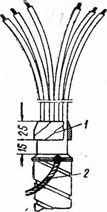
Rice. 77. Control cable termination with plastic insulation
1 - fastening winding; 2 - ground wire
Termination of cables with plastic insulation (Fig. 77). Installation of the end seal of a cable with polyvinyl chloride core insulation is reduced to cutting the end of the cable (sequential removal of the outer coverings) and installing a winding device from polyvinyl chloride tape on the spine.
The end seal of a cable with polyethylene core insulation is installed in the same way as a cable with polyvinyl chloride insulation, but polyethylene insulation requires protection from light and fire. This protection is mandatory in all cases and is carried out using polyvinyl chloride tubes.
End sleeves and seals reliably protect the cable insulation from moisture, solar radiation, harmful atmospheric influences(chemically active environment, conductive dust, etc.). They have high electrical strength and discharge characteristics.
Unlike couplings, end couplings are mounted and operated in only one environment - in air. End seals are used indoors or in sealed cabinets outdoors.
Due to various designs cables and operating conditions apply a large number of end couplings and terminations.
Below we discuss the design and installation technology of the most common designs of end couplings and seals.
End metal couplings outdoor installation voltage up to 10 kV(Fig. 95, a). For terminating in outdoor installations three-core cables with paper insulation with a core cross-section of up to 240 mm 2 for voltages of 6 and 10 kV, three-phase end couplings are used: KNA - s aluminum body, KNCh - with cast iron, KNSt - with steel.
Rice. 95. Outdoor terminations for cables with voltage up to 10 kV with paper insulation:
a - KNA, b - KMA, c - KNE;
1 - copper cap, 2 - filling hole, 3 - housing, 4 - ground wire, 5 - cone, 6 - gland, 7 - cable core, 8 - insulator, 9 - tip, 10 - contact head, 11 - housing cover, 12 - winding of cotton tapes coated with compound
The cable is cut according to the general instructions given in Chapter. VIII.
Before installation, check the dimensions of the end coupling. Special attention pay attention to the location of the external contact bars of the coupling insulator heads relative to the front wall of its body. The tires must correspond to the location of the contacts of the connected electrical installation. The gland is removed from the coupling body and the required slot is selected in it, the diameter of which corresponds to the diameter of the cable being inserted. The gland body is placed on the cable armor and temporarily moved outside the groove.
The cable is bent taking into account the permissible bending radius and secured vertically. At the same time, the location of the separated cores is checked; the middle core should be 8-15 mm longer than the outer ones. The wires are separated, paper insulation is secured and cut. After terminating the cores, the coupling body is prepared for filling with mass. To do this, remove all temporary bandages, color tapes, materials that temporarily protect the cutting spine from solder and other foreign particles, and waist insulation. The coupling body is heated and coated with a scalding compound. The cable cores are inserted into the housing 200 mm.
Nozzles from the pipe are inserted into the outer holes of the housing and pushed onto the cores. Carefully bending the outer cores, they are directed into the corresponding holes in the housing and the housing is advanced so that the middle core extends 280 mm out of it. In accordance with the technology described in technical documentation, assemble the bolts with washers and nuts of the contact heads and the outer insulators on the coupling body. The ends of the cable cores are connected to the contact bars of the insulator heads and secured with bolts.
The coupling body is heated again with a burner flame to 50-60 °C. The heated filling compound is used to fill the entire internal volume of the coupling through the hole in the middle insulator, which, after topping up, is installed in place. The composition is added through the middle insulator until it appears in the heads of the outer insulators. The caps are soldered to the outer heads of the insulators. Then the middle insulator is filled to the top with the filling compound. The coupling is grounded with a copper stranded wire. After the coupling has cooled to 50-60 °C, it is again topped up with the compound through the middle insulator.
After soldering the cap onto the head of the middle insulator, the coupling is lifted to the installation site, protecting it from possible tensile forces between it and the cable. If necessary, turn the coupling simultaneously with the cable.
Mast end couplings for outdoor installation with voltage up to 10 kV. During the transition cable lines For overhead three-core cables with paper insulation with voltage up to 10 kV, mast end couplings KMA with aluminum and KMCh with cast iron housings are used (Fig. 95,b).
In contrast to the installation of KN couplings, after connecting the tips of the cores to the contact rods (the middle core is 8-12 mm shorter than the outer cores), the housing is filled through the filling holes in the cover. When pouring and topping up, the filling compound should not reach the level of the filling hole and lid by 30-40 mm. The presence of a gap serves as a compensator when the volume of the filling composition changes depending on the ambient temperature.
End epoxy couplings for outdoor installation with voltage up to 10 kV. To terminate cables with paper insulation for voltages up to 10 kV, KNE couplings are used (Fig. 95, c). The coupling consists of a housing and three epoxy bushings for the cable cores. At the installation site, the coupling is put on the cut end of the cable and filled with epoxy compound, which ensures the tightness of the coupling and also increases its electrical and mechanical strength. The coupling installation technology is described in the technical documentation.
End mast couplings for outdoor installation with voltage up to 1 kV. To connect cables to overhead power lines with voltages up to 1 kV, mast couplings KMA, KMCh and KMSt are used. Installation of couplings is carried out in the same sequence as mast couplings with voltages up to 10 kV. The cable cores are separated and bent so that they are in the same plane. The angle of inclination of the cable axis is 15°.
To connect paper-insulated cables to openly installed electrical equipment and overhead power lines with voltages up to 1 kV, KNE epoxy terminations are also used, which consist of a factory-cast housing and four epoxy bushings. During installation, the fourth (zero) core of the cable is shortened locally so as to ensure complete filling of the tubular part of the tip in the insulator for this core.
When installing the coupling, the compound is first poured to the level of the insulator of the fourth core, after which a cap is put on the insulator and secured. Filling is continued in the same way as in couplings for voltages of 6-10 kV.
End epoxy seals for voltage up to 10 kV indoor installation. KVE terminations with a housing made of epoxy compound and tubes for sealing conductors are mainly intended for terminating cables indoors. In outdoor installations, seals are used under the condition that they are fully protected from atmospheric influences and sun rays and installed in any position. The scope of application of seals depending on environmental conditions is defined in the technical documentation.

Rice. 96. End epoxy seals of the internal installation KVEn and KVEK with tubes made of nayrite or silicone rubber:
1 - grounding wire, 2, 4 - bands, 3 - winding, 5 - body, 6 - cable core, 7 - tube, 8 - clamp, 9 - tip, 10 - adhesive layer of varnish KO-9I6, 11 - shell
KVE end seals are produced in various designs: KVEtv - with heat-shrinkable PVC tubes; KVEn - with tubes made of nayrite rubber (Fig. 96); KVEk - with organosilicon; KVEt - three-layer tubes (Fig. 97), consisting of a middle polyethylene layer and inner and outer layers of PVC.
Rice. 97. End epoxy seal of the internal KVEt installation:
1 - wire bandage, 2, 4 - winding made of PVC tape, 3 - ground wire, 5 - housing, b - core insulation, 7 - three-layer tube, 8 - winding made of cotton tape impregnated with epoxy compound, 9 - tip, 10 - yarn bandage, 11 - waist insulation
The seal body in a permanent plastic form with a lid for all versions is filled with epoxy compound at the installation site. If such a form is not available, the seal body is cast in a removable mold from paper coated with plastic film, plastic or metal.
The technology for installing epoxy end seals of various designs has many of the same operations.
Let's take a closer look at the installation of KVEtv end seals. The cable end is cut in the usual way (see Chapter VIII). When installing the grounding wire, its end in a section 100 mm long at the place of soldering to the shell and armor is unraveled so that it has minimum thickness. The grounding wire is fixed and soldered on the steps of the shell and armor no more than 35 mm from the cut of the armor or hose.
Taking into account the thickness of the soldered ground wire, the diameter of the cable armor step is measured. Based on this size, select the appropriate diameter of the body neck, cutting off its steps of smaller diameters. The plastic form is placed over the cable cut and moved down.
During installation, the cores and the inner surface of the plastic mold are wrapped in clean paper or cloth, and the cable cores are thoroughly degreased. The cores are wrapped with adhesive PVC tape for protection paper insulation from unrolling the tapes when putting on the tubes.
The lid of the plastic mold is placed over the separated conductors and pushed down. The cores are terminated, and their insulation is restored using LETSAR LPM tape.
The diameter of the heat-shrinkable tubes is selected depending on the cross-section and design of the cores, and the length so that the upper end of the tube covers the entire cylindrical part of the tip, while Bottom part The tubes must fit into the epoxy casing at a distance of at least 50 mm.
Heat-shrinkable tubes are placed on the cylindrical part of the tip and are uniformly heated with a flame. gas burner, moving it from the middle of the area to be seated, first up and then down. After shrinking, the excess on top of the tube is removed with a knife, and the tubes are sealed with metal bands.
After degreasing, the surfaces of the cutting steps are coated with KO-916 varnish and two layers of LETSAR LPM or LETSAR tape with 50% overlap. In the absence of these tapes, winding from cotton tapes with coating of each layer with epoxy compound is allowed. In this case, KO-916 varnish is not used. Below, the ends of the heat-shrinkable tubes are covered with PED-B glue.
The plastic mold is pushed onto the armor stage and secured in place with PVC tape. Place a lid on the mold and fill the mold with the compound along the filling tray.
A number of features provide technological process installation of KVEn and KVEk end seals. The lower ends of the Nairite tubes are processed with a file, creating a rough surface for reliable adhesion to the epoxy compound. Before pouring the compound, the cleaned surfaces of the tubes are thoroughly degreased.
The surfaces of nayrite and organosilicon tubes filled with the compound are coated with KO-916 varnish.
The tubes are put on the cores and temporarily moved down (before the cores are terminated with tips). Then the tubes are pushed onto the tubular part of the tip and sealed with metal bands. To avoid cutting through the pipes, one or two turns of PVC tape are first wrapped under these bandages.
When installing KVEt end seals, before putting the tubes on the cores, the PVC and middle polyethylene layers are cut off from their ends. The remaining inner PVC layer of the tubes is processed with a file and the treated surface is lubricated with PED-B glue. The same glue is used to cover the outer PVC layer in the part of the tubes that will be filled with epoxy compound.
Installation of epoxy seals located at the lower ends of cables laid with a level difference of more than 5 m is carried out, taking measures to prevent the penetration of the cable's impregnating composition into the uncured compound. The composition, in the same way as when installing epoxy couplings, penetrates under pressure into the compound, creating cavities and fistulas in it, reducing the electrical strength of the seal.
The most effective measures against these factors are raising the lower end of the cable while the compound is curing, installing a seal on the lower or both ends of the cable before laying it (when preparing the cable on production lines in workshops) or using the local freezing method (see § 39).
If it is impossible to implement the specified measures, installation of terminations begins from the upper end of the cable or from its preliminary sealing. The termination body at the lower end of the cable is filled with a seasoned compound, i.e., after introducing the hardener, the compound is kept until the start of polymerization is detected (barely noticeable self-heating and the beginning of thickening of the compound).
End seals for internal installation with self-adhesive tapes for cables with voltage up to 10 kV with paper insulation. The most common termination for internal installation on cables with voltages up to 10 kV with paper insulation is KVsl (Fig. 98, a).

Rice. 98. Termination of the internal installation of KVsl for cables with voltage up to 10 kV with paper insulation:
a - seal, b - conical sealing liner;
1 - tip, 2, 3 - windings made of PVC tape and LETSAR tape or LETSAR and LETSAR LPT, 4 - paper insulation of the core, 5 - cross-shaped sealing winding, 6, 9 - central and side liners, 7 - bandage made of LETSAR tape, 8 - sealing winding, 10 - cut line when making the liner
For this sealing, a factory set of materials necessary for the work is supplied to the site. Sealing is used when the level difference is up to 10 m; under other conditions, KVE should be used. The length of the termination is taken depending on the connection conditions, but not less than 150 mm at a voltage of 1 kV, 250 mm - 6 kV and 400 mm - 10 kV. Cable cutting, fastening of the ground wire and termination of cores are performed using the methods described above.
The outer surfaces of the shell, semiconducting paper, core insulation and the tubular part of the tip are thoroughly wiped and degreased. KO-916 varnish is applied to the tubular part of the tip and to the shell stage.
Along the cores, starting from the belt insulation stage to the contact part of the tip, the LETSAR tape is wound in two layers with 50% overlap of the previous turn and pulled out during the winding process so that its width is 60-70% of the original width.
During the winding process, the tape fills the gaps between the tip and the insulation of the cable cores, and also seals the “spine” of the core cutting. To do this, the tapes are twisted into four sealing cones: one - central, which is installed in the “spine” between three cores and three - side ones - with outside cutting between each pair of cores. For a four-core cable, five cones are made. The height of the cone for all sizes of embedments is 30 mm, and the diameter of the base of the cones is selected according to the tables specified in the technical documentation. The production of cones is carried out without tensioning the tapes, followed by cutting off the internal cone formed during the winding process (Fig. 98, b).
The central cone is inserted as deeply as possible into the “root” of the cut veins. Then the conductors are compressed and a bandage is made with LETSAR tape at a distance of 30 mm from the end of the waist insulation. After compacting the “spine” of the cutting, bandage winding is performed, covering all the voids in the “spine” of the cutting with LETSAR tape. To do this, wrap each core with a transition to the neighboring ones. A three-layer winding is performed on top of the banding at a distance of 30 mm from the end of the belt insulation along its steps and the metal sheath with an extension of 20 mm to the outer covers of the cable. During the winding process, the tape is pulled out so that its width is 60-70% of the original.
On top of the windings with LETSAR tape on the cores, in the “spine” of the seal and on the steps of the metal sheath of the cable, wind the adhesive PVC tape in one layer with 50% overlap. When installing KVsl seals, two self-adhesive tapes LETSAR and LETSAR LPT are used. LETSAR LPT tape is placed between LETSAR and PVC tapes.
End seals for voltages up to 10 kV for indoor installation in steel funnels. KVB end seals in steel funnels filled with bituminous mass can be used for terminating cables with voltages up to 10 kV inside dry rooms in all climatic regions, with the exception of subtropical and humid ones. These seals are installed only in vertical position with the direction of the veins upward. KVB seals (Fig. 99) consist of a funnel 5, made of roofing steel 0.7-0.8 mm thick, a cover 4 with holes into which porcelain bushings 3 are installed (at voltages up to 1 kV, covers and bushings are not installed). Through hole 10 in the lid, the funnel is filled with bituminous mass. The cable cores are sealed with a winding of insulating tapes coated with varnish.

Rice. 99. KVB end seals with a steel funnel for cables with voltage up to 10 kV with paper insulation;
a - KVBo termination with an oval funnel, b - KVBk termination with a round funnel, c - small-sized KVBm termination up to 1 kV;
1, 8 - lower and upper half-clamps, 2 - cable core, 3 - porcelain bushings, 4 - cover, 5 - funnel, 6 - bolt, 7 - nut, 9 - ground wire, 10 - filler hole cover, 11 - resin tape
KVB seals are produced in various designs: KVBo - with funnels oval shape and the location of the veins in the same plane; KVBk - with funnels round shape and the location of the veins at the exit from the funnel along the vertices of an equilateral triangle; KVBm - with oval small-sized funnels that do not have covers and are mounted without porcelain bushings. Installation of seals is carried out according to the technology given in the technical documentation.
Outdoor terminations for cables with voltage up to 35 kV with plastic insulation. Cables with plastic insulation are terminated using elastomeric couplings PKNR and PKNRO. Couplings are assembled at the installation site from parts made of rubber (elastomer) insulating and semi-conducting mixtures. PKNR end couplings with voltages of 1 - 6 kV are made similarly to PKVE terminations. Additional structural elements are heat shrinkable tubes and elastomeric insulators. The coupling installation technology is given in the technical documentation.
End seals for internal installation on cables with voltage up to 10 kV with plastic insulation. For terminating power cables with a core cross-section of up to 240 mm 2 in dry rooms, PKV terminations are used, in damp rooms and subtropical areas - PKVE.

Rice. 100. End seal of internal PKV installation for cables with voltage up to 10 kV with plastic insulation:
a, b, c - for voltages up to 1, 6 and 10 kV;
1 - ground wire, 2 - winding made of adhesive PVC or self-adhesive tape or PVC tube, 3 - bandage made of raw threads, 4 - cable lug, 5 - PVC hose (sheath), 6 - conical winding, 7 - metal screen, 8 - screen made of semiconducting material
When sealing with PKV plastic insulation on 6 kV cables, the metal screen is grounded (Fig. 100). When terminating a cable with a voltage of 10 kV, a conical winding of adhesive plastic tape is made on each core, on top of which a semiconducting screen and a metal screen with a ground wire soldered to it are applied (Fig. 101).
Rice. 101. Cone winding for 10 kV cables with plastic insulation:
1 - core insulation, 2 - conical winding, 3 - ground wire, 4 - screen made of semiconducting material, 5 - metal screen, 6 - winding over the screen, 7 - hose
For PKVE terminations (Fig. 102), a housing cast from an epoxy compound is used, and the junction of the cable core with the tip is sealed against moisture penetration into the cable.

Rice. 102. End seal of PKVE internal installation when installed in damp rooms for cables with voltage up to 10 kV with plastic insulation;
a, b, c - for voltage 1-3, 6 and 10 kV;
1 - tip, 2, 5 - winding made of self-adhesive or cotton tape, 3 - coupling body, 4 - bandage, 6 - ground wire
Before cutting, the end of the cable is straightened to a length of A + 0.5 m. Dimension A (the length of the cable end to be cut), taken depending on the conditions for connecting the cores to electrical receivers, must be such that the distance from the grounded parts of the termination (armor tapes and screens) to the cable lug was at least 250 mm at a voltage of 6 kV and 400 mm at 10 kV. For cables with a core cross-section of up to 10 mm, size 2 A is increased by the length necessary to bend the ends of the cores into a ring.
The end of the cable is cut using the technology described in Chapter. VIII, while size G (see Fig. 75) is equal to the length of the tubular part of the tip plus 15 mm. The cable cores are bent taking into account the permissible bending radius.
To protect the polyethylene insulation of the core from light aging, a PVC plastic tube is put on it before termination. The inner diameter of the tube should be 1-2 mm larger than the diameter of the core insulation. This operation can also be performed with a two-layer wrapping with adhesive PVC tape. The end of the winding at the tip is secured with a thread bandage. Polyvinyl chloride insulation The cable cores are not additionally protected, since they are quite resistant to light aging. When installing PCV terminations for a voltage of 6 kV, the tapes of the metal and semiconducting screens are wound up and bent down at a distance of 25 mm from the place where the hose is cut. At a distance of 40 mm from the end of the hose, a bandage is applied and the tapes of the semiconducting screen are wound up. Along the entire length of the vein, the graphite layer (aquadag) is washed off with gasoline or acetone.
The bent strips of the metal screen are cut at a distance of 50-60 mm from the bend line and the copper strips are tinned on the upper side with tin solder and the aluminum strips are tinned with solder A. The ground wire is soldered with a soldering iron. A winding of PVC tape is applied to the sections of the cores on which the screen steps are left.
When installing PKV terminations for a voltage of 10 kV, tapes of metal and semiconducting screens are wound up to the point where the hose is cut, but are not cut off, but left for subsequent installation. In the same way as on cable cores for a voltage of 6 kV, the aquadag is removed.
Along the PVC insulation of the cores, starting from a point 30 mm from the end of the hose, apply a conical winding of adhesive PVC tape (for polyethylene insulation - a winding of adhesive polyethylene tape). The tapes of the semiconducting screen, previously wound from the cores, are wound onto a conical winding with 30-50% overlap, at its top these tapes are secured with a bandage, and their excess is cut off.
The tapes of the general metal screen, previously wound from the cores, are tried on and cut so that after they are wound onto the cone, they do not reach the cut point of the semiconducting screen by 5 mm. The ends of the metal screen strips are temporarily retracted and tinned. A grounding wire is soldered to the tinned areas of the tapes with a soldering iron. The metal tapes are again wound onto the conical winding and secured with a wire bandage at a distance of 5 mm from the cut of the semiconducting screen. The folds on the surface of the metal screen are smoothed with a wooden hammer.
When installing the epoxy end seal PKVE of an internal installation for cables with plastic insulation, all stripped areas of PVC insulation are coated with PED-B glue for adhesion to the epoxy compound. Subject to the same treatment PVC insulation tubes covered with polyethylene core insulation.
On a section of armor 50 mm long, a winding of two layers of cotton tape is applied, with each layer coated with a compound. The same winding is applied to the tubular part of the tip and the section of the uninsulated core. The removable mold for pouring is made from polyethylene film and other materials that do not have adhesion to the epoxy compound.
When installing the PKVE seal on a 6 kV cable (before putting on the removable form), the bent screen strips are grounded. PVC tubes are placed on the polyethylene-insulated cable cores (to the point where the semiconducting screen tapes are cut).
When installing a PKVE termination on a 10 kV cable (before putting on the removable form), a conical winding is performed on each core. Tubes made of PVC plastic compound are placed on the polyethylene insulation of the core to the top of the cone winding.
After installing the removable mold, check the geometric dimensions, including the distance of the cores from the mold wall (at least 5 mm), and fill the mold with compound. After the epoxy compound has cured, after 20-24 hours, the mold is removed and the seal is coated in two layers with GF-92ХС or EP-51 enamel.
PKV terminations with voltage up to 1 kV (see Fig. 100, a) are a stripped end of the cable terminated with a lug. The area where the conductors are routed is insulated with two or three layers of adhesive PVC tape. Polyethylene insulation of cores is protected from light aging in the same way as insulation for terminations for a cable voltage of 6 kV.
When cutting, it is necessary that the distance from grounded parts (armor tapes and screens) to the cable lug is at least 150 mm. For cables with a core cross-section of up to 10 mm2, this distance is increased by the size necessary to bend the ring under the contact clamp.
Terminations for cables with voltage 20-35 kV with paper insulation. Single-phase brass end couplings for outdoor installation KNO-20 and KNO-35, epoxy KNEO-35 are designed for terminating paper-insulated cables and cables with separate metal sheaths on each core in networks with an ungrounded neutral.
Brass couplings KNO are also used for terminating cables in indoor installations. If there is a compensator, the brand of the coupling is designated KNOk. Couplings with compensators are used for terminating cables in areas with hot climates, as well as inside heated rooms.
Instead of KNEO-35 epoxy couplings, KVEO-35 couplings are used in internal installations.
The design of the KNOk-35 coupling (Fig. 103) consists of a brass cone 2 with a base plate 13, on which an insulator 10 is installed, hermetically reinforced with the upper 4 and lower 3 flanges. Oil-resistant rubber is laid as seals between the flanges and ends of the insulator. 9. On the upper flange of the insulator there is a contact flange 5 with an input copper cap 8. To compensate for temperature volumetric changes in the core, a copper cap is welded to the cap flange flexible wire 7. The other end of the wire is connected to a tinned copper sleeve 6, into which the cable core is soldered or pressed. A winding from roll 11 is applied to the paper insulation of the core, on the lower cone of which there is a screen 12 made of tinned copper cord. The coupling cone with cuff 1 is soldered to the metal sheath of the cable. The internal cavity of the coupling is filled with rosin mass, which is drained through fitting 14.
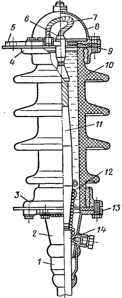
Rice. 103. End coupling for outdoor installation KNOk-35 for cables with voltage up to 35 kV with paper insulation and separate metal sheaths on the cores:
1 - lead cuff, 2 - cone, 3, 4 - lower and upper flanges, 5 - contact flange, 6 - sleeve, 7 - compensator - copper flexible wire, 8 - copper cap, 9 - gasket, 10 - insulator, 11 - roll winding, 12 - screen, 13 - base plate, 14 - fitting for draining mass
The KNEO-35 end coupling (Fig. 104) consists of an insulator 4 cast from an epoxy compound by centrifugal casting in a removable mold, a body 6 cast together with an internal aluminum or lead screen 7, an epoxy cover 3 and a tip 1 secured with a nut 2. B the lower part of the coupling has a metal flange 8 for attaching the coupling body to supporting structure. On the paper insulation of the core, a winding 9 of two layers of glass tape is applied with 50% overlap and each turn is coated with an epoxy compound. The inside of the coupling body is filled with epoxy compound 5.
Rice. 104. Termination epoxy coupling for outdoor installation KNEO-35 for cables with voltage up to 35 kV with paper insulation and separate sheaths on the cores:
1 - tip, 2 - nut, 3 - epoxy cap, 4 - epoxy insulator, 5 - filling with epoxy compound, 6 - epoxy cone, 7 - cone screen, 8 - flange, 9 - winding made of glass tape with epoxy compound
The design of the end coupling of the KVEO-35 internal installation is similar to the design of the KNEO-35 coupling and differs only in size.
The book contains only the most commonly used terminations and terminations with voltages of 1 - 35 kV, characteristic of individual groups of cable fittings. More complete information about other terminations and terminations (indoor terminations, electrostatic precipitator terminations, etc.) is provided in the technical documentation.
Control questions
- Give the classification of cable joints and terminations.
- Which preparatory work performed before installing the SS lead coupling?
- Which additional measures accepted when pouring epoxy compounds into couplings at ambient temperatures below 10 and above 25 ° C?
- What are the features of installing epoxy end seals with a level difference of more than 5 m?
- How is the end seal sealed with self-adhesive KVsl tapes for paper-insulated cables?
DEVELOPED by the State Makeevka Order of the October Revolution Scientific Research Institute for Work Safety in the Mining Industry (MakNII)
AGREED with Gosgortekhnadzor of the USSR
APPROVED by the USSR Ministry of Coal Industry
1. General Provisions
1. General Provisions
1.1. This instruction applies to terminations and connections of armored cables with paper and plastic insulation with copper wires when installing them in underground mine workings.
1.2. Work on the installation of end seals and couplings must be performed by specially trained personnel under the supervision of engineering and technical workers.
By the start of installation, personnel must be provided with the necessary material, tools and devices specified in Appendices 2 and 3, 4.
1.3. When cutting the cable, the outer protective covering is sequentially removed 1
, armor 2
, lead sheath 3
, waist 4
and phase 5
cable insulation (Fig. 1). The cable length must correspond to the values given in Table 1.
Fig.1 Cable end preparation
Fig.1 Cable end preparation
Table 1
|
Core cross-section, mm |
Dimensions, mm |
|||||
1.4. On distance A a bandage is applied from the end of the cable 7
from wire (two or three turns) and remove the outer cover 1
.
1.5. At length B a bandage is applied from the cut of the outer covering 8
for armor 2
. The armor around the bandage is cut with a hacksaw and removed. Lead sheath 3
clean from contamination with a technical cloth soaked in gasoline.
1.6. Markings are made along the lead sheath to make two circular and two longitudinal cuts. On distance ABOUT from the point where the armor is cut, the first annular cut is made along the lead sheath, and at a distance P from it there is a second annular cut. From the second annular cut to the end of the cable, two longitudinal cuts are made at a distance of 10 mm from one another. Cuts in the lead sheath are made to half its thickness with a knife with a limiter at the blade. First, the lead strip is separated between two longitudinal cuts, and then the entire lead sheath is removed until the second annular cut. The lead belt between the first and second cuts is removed immediately before sealing the end of the cable, i.e. when the belt insulation and filler between the cores are removed, and the cores 6
separated and covered with sealing insulation.
1.7. The selection of end seals and couplings is made according to Table 2.
table 2
Scope of application of end and connecting couplings and seals
|
Name of end seal or coupling |
Purpose |
Scope of application in underground mine workings |
Level difference between cable ends, m |
|
|
dry workings |
raw workings |
|||
|
Sealing in the input device of mine electrical equipment with filling with cable mass |
|
Allowed |
||
|
End epoxy dry seal with three-layer plastic tubing |
For paper-insulated cables rated for voltages above 1000 V |
Should be applied |
Should be applied |
|
|
End epoxy dry seal with Nyrite rubber tubes |
|
Should be applied |
Allowed |
|
|
End dry sealing with rubber gloves |
For paper-insulated cables rated for voltages up to 1000 V |
Allowed |
Should not be used |
|
|
End dry sealing with PVC tape and varnishes |
|
Should be applied |
Should be applied |
Not limited |
|
Termination of EVT cable with epoxy compound filling |
For cables with insulation rated for voltages above 1000 V |
Should be applied |
Should be applied |
Not limited |
|
Dry termination of EVT cable |
For cables with insulation rated for voltages up to 1000 V and above |
Should be applied |
Should be applied |
Not limited |
|
Cast iron (or stamped steel) coupling with cable filling |
For cables with insulation rated for voltages up to 1000 V and above |
Allowed |
Allowed |
|
|
Steel coupling filled with epoxy compound (for EVT cable) |
Should be applied |
Should be applied |
||
|
Connecting steel coupling without filling (for EVT cables) |
For cables with insulation rated for voltages up to 1000 V and above |
Should be applied |
Should be applied |
|
|
Note. The level difference in meters is given for cables with impregnated paper insulation |
||||
2. Sealing the ends of armored cables with paper insulation with cable mass
2.1. The end coupling (funnel) is disconnected from input device and put on the cable. The end of the cable is cut in accordance with Fig. 1. In this case, the length of the cores is determined by the size of the input device.
2.2. The insulation on the conductors is removed to the length necessary for installing the lugs. Tips are placed on the ends of the cores and crimped.
2.3. The phase insulation is sealed using oil and moisture resistant insulation: PVC tapes, PVC pipes or nayrite. To do this, wind each core insulating tape with a 10% overlap in three to four layers (or put on a tube) in the area from the tip ear to the cutting spine. Bandages made of coarse threads are placed on the ends of the winding to prevent unwinding. For better sealing, the insulation is glued with glue N 88 to the copper tip and secured with a bandage of twine, which is then coated with moisture-resistant varnish (glue).
2.4. The lead sheath is cleaned with a knife until it shines and a steel clamp is installed in this place, to which a grounding conductor is connected. The length of the grounding conductor must be sufficient to connect it to the internal grounding terminal of the electrical installation housing.
Direct connection of the lead sheath of the cable to the internal ground terminal is permitted.
2.5. A winding of tarred tape is made on the cable at the location where the coupling neck is installed. Using a steel clamp, the coupling is secured to the cable.
2.6. The end sleeve is filled with cable mass. As the mass cools, top up.
2.7. Power conductors are connected to the terminals of electrical equipment, and the lead sheath is grounded. To do this, the grounding conductor, attached with a clamp to the lead sheath, is connected to the internal grounding clamp of the electrical equipment housing.
2.8. The funnel is connected to the cable box. The steel armor of the cable is grounded, for which a steel clamp is placed on the armor near the coupling. Using a grounding conductor, the clamp is connected to the external grounding terminal of the electrical equipment.
2.9. In underground mine workings, it is allowed to connect cable cores to electrical equipment without lugs (Fig. 2). In this case, the paper insulation is removed from the core 2
at a length of 70 mm and remove 50% of the wires to form a loop 3
. The ends of the wire loops using a bandage 4
fastened to the core. Vein section A With the paper insulation removed, they are cleaned from oil with gasoline and coated with glue N 88, after which has dried, a leveling winding is applied to cover the paper insulation. 5
from PVC tape.
Fig.2. Sealing the end of the conductor without using a ferrule
Fig.2. Sealing the end of a conductor without using a ferrule:
1 - lived; 2 - paper insulation; 3 - a loop bent from the cable core; 4 - bandage made of copper wire; 5 - leveling winding; 6 - sealing insulation layer; 7 - bandage made of harsh threads
2.10. To seal the phase insulation, winding 6
put on the area A all the way to the loop 3
. A bandage of coarse threads is applied to the sealing winding 7
, which is then coated with moisture-resistant varnish.
2.11. General form cable termination mounted in the input device of mine electrical equipment is shown in Fig. 3.
Fig.3. General view of the cable termination mounted in the input device of mine electrical equipment
Fig.3. General view of the cable termination mounted in the input device of mine electrical equipment
1 - power core; 2 - waist insulation; 3 - lead sheath; 4 - armor; 5 - grounding conductor; 6 - grounding clamps installed respectively on the lead sheath and armor; 7 - funnel filled with cable mass
3. Sealing the ends of armored cables using epoxy compounds and three-layer plastic tubes
3.1. Terminations with three-layer tubes are recommended for terminating cables laid in wet workings. These seals differ from others in their smaller size and ease of installation.
The list of necessary tools is given in Appendix 3.
3.2. The end of the cable is cut in accordance with Fig. 1. The dimensions of the cuts must correspond to the data in Table 1.
If necessary, these dimensions can be increased.
3.3. The insulation is removed from the ends of the conductors in an area sufficient to install the tip. Before removing the insulation in the specified area, a bandage of two or three turns of raw thread is applied to the edge of the remaining insulation.
3.4. After cutting the cable, the insulation of the cores and the spine are wrapped with insulating PVC tape to protect it from moisture.
3.5. To seal the cores, elastic three-layer tubes are used (with inner and outer layers made of PVC, the middle one made of polyethylene). Table 3 shows the dimensions of three-layer tubes.
Table 3
|
Core cross-section, mm |
Tube dimensions, mm |
Dimensions (Fig. 4), mm |
||||
|
inner diameter |
PVC layer thickness |
thickness of the polyethylene layer |
||||
3.6. The length of the tubes is determined by the length of the cores in such a way that the upper part of the tube completely covers the cylindrical part of the tip, and the lower end of the tube, cut at an angle of 30° (which makes it easier to put it on the core), enters the epoxy compound by at least 50 mm.
3.7. Before putting it on the cable cores, the outer polyvinyl chloride and middle polyethylene layers are removed from the tube at a distance of 20 mm from the oblique cut, after which the inner polyvinyl chloride layer is processed with a file. The treated surface of this layer is lubricated with PED-B glue. The outer polyvinyl chloride layer in the part of the tubes that will be filled with epoxy compound is subjected to the same treatment, followed by lubrication with PED-B glue.
3.8. When performing the termination, preliminary wiring of the cores is carried out, avoiding sharp bends and damage to the paper insulation. Remove part of the lead cable sheath between the two ring cuts. A bandage of coarse threads is applied to the edge of the waist insulation. A rubber ring and a cable funnel are put on the cable.
3.9. A layer of epoxy compound is applied to the degreased paper insulation of the cores and cable spine and wound with keeper tape in two layers with 50% overlap. Each layer and winding surface is generously coated with epoxy compound.
3.10. Three-layer tubes are put on the veins, which, when terminating the wires, are moved to the spine with tips.
3.11. Tips are pressed onto the cores. The surface of the cylindrical part of the tip is cleaned of burrs with a file, lubricated with an epoxy compound, after which a keeper tape is wound on it. A three-layer tube is pressed onto this part of the tip over the keeper tape and secured with a bandage made of harsh threads coated with an epoxy compound.
3.12. To ensure the tightness of the seal, a two-layer winding of keeper tape is applied to the lead sheath and armor, with each layer coated with an epoxy compound. The surface of the lead shell and armor must first be degreased with gasoline.
3.13. Before filling the coupling with compound, check that it is installed correctly. The coupling must be positioned so that the cable cores are at the same distance from the coupling body.
3.14. Filling with epoxy compound is carried out to the required level. Before pouring, the compound is thoroughly mixed again. The epoxy compound is prepared and poured in the manner described in Appendix 2.
3.15. A general view of the epoxy seal with three-layer plastic tubes is shown in Fig. 4.
Figure 4. General view of epoxy seal with three-layer tubes
Figure 4. General view of an epoxy seal with three-layer tubes:
1 - tip; 2 - winding from keeper tape coated with epoxy compound; 3 - three-layer tube; 4 - lived in factory isolation; 5 - epoxy casing; 6 - bandage made of coarse threads; 7 - waist insulation; 8 - ground wire; 9 - bandage made of galvanized steel wire; 10 - winding from keeper tape
The material consumption for installing one epoxy seal is given in Table 4.
Table 4
|
Name of material |
Quantity |
|
Three-layer plastic tube TUMI 194-71, pcs. |
|
|
Temporary mold made of roofing iron, pcs. |
|
|
Epoxy compound K-115 or K-176 MRTU-6-05-1251-69 or TU6-05-041-358-72, kg |
|
|
|
|
|
Grounding wire with pressed-on cable lug GOST 7386-70*; GOST 1956-70**, pcs. |
|
|
________________ |
|
|
Keeper tape (GOST 4514-71*), m |
|
|
________________ |
|
|
Galvanized steel wire 1.5 mm (GOST 1526-70*), g |
|
|
________________ |
|
|
Heavy threads (GOST 6309-73*), m |
|
|
________________ |
|
|
Twisted twine (GOST 18403-73*), m |
|
|
________________ |
|
|
PVC tape (GOST 16214-70*), m |
|
|
________________ |
|
|
|
|
|
Technical napkins 300x300 (GOST 11680-65*), pcs. |
|
|
________________ |
|
4. Grounding of cable sheath and armor
4.1 The grounding wire is connected to the lead sheath and armor using galvanized steel clamps.
4.2. Grounding of the lead sheath inside the cable entry is carried out using a steel clamp placed on the stripped sheath. One end of the grounding wire is connected to the clamp, and the other to the grounding clamp of the electrical equipment.
4.3. The cable armor is grounded outside the input device, for which it is cleaned with a file near the input device and a steel clamp is placed on it. One end of the grounding wire with a cross-section of 25 mm is connected to the clamp, and the other to the external grounding clamp of the electrical equipment.
5. Installation of dry cable termination in the input device
5.1. After completing the termination and locking devices, a rubber ring and a cable funnel are put on the cable, the cable cores are connected to the feed-through terminals of the electrical equipment, and the lead sheath of the cable is connected to the grounding clamp.
5.2. With a cable sheath diameter smaller than internal diameter rubber ring, where the latter is installed, a sealing band is wound onto the lead sheath and armor. For compaction, keeper tape impregnated with epoxy compound or adhesive PVC tape is used. The width of the sealing band should be 20-30 mm greater than the width of the rubber sealing ring. The edges of the bandage should be tapered. Upper layer The bandage and its ends are coated with epoxy compound. Then the rubber sealing ring through which the cable was previously passed is put on the bandage, and the cable entry is sealed using a flange and bolts.
5.3. The cable funnel is pushed onto the termination and connected to the input device.
5.4. A galvanized steel grounding clamp is placed on the cable armor from the outside of the input device. The clamp is tightly tightened and connected to the external grounding clamp of the electrical equipment housing using a copper wire.
5.5. A general view of the dry termination of the input device cable is shown in Fig. 5.
Fig.5. General view of the dry termination of the input device cable
Fig.5. General view of the dry cable termination of the input device:
1 - introductory box; 2 - pass-through studs; 3 - grounding pin; 4 - funnel; 5 - clamp for grounding the lead sheath; 6 - rubber ring; 7 - sealing flange; 8 - clamp for grounding the armor; 9 - grounding jumper
6. End seals of paper-insulated armored cable using rubber gloves
6.1. The materials required for installation of seals are given in Table 5.
Table 5
|
Name of material |
Quantity |
Note |
|
Nairite tubes (gloves), pcs. |
||
|
Shape, pcs. |
Depending on the type of embedment |
|
|
Epoxy compound K-115 MRTU-6-05-1251-69 or TU-6-05-041-358-72 or K-176 (STU-130-14148-63), kg |
||
|
Hardener (TU6-02-594-70), g |
||
|
Grounding wire with cable lug, pcs. |
||
|
Galvanized steel wire 1.5 mm (GOST 1526-70), g |
||
|
Keeper tape (GOST 4514-71), m |
||
|
Heavy threads (GOST 6309-73), m |
||
|
Twisted twine (GOST 18403-73), m |
||
|
PVC tape (GOST 16214-70), m |
||
|
Tips (GOST 7386-70), pcs. |
||
|
Technical napkins 300x300 (GOST 11680-65), pcs. |
||
6.2. Rubber gloves of a special design are designed to protect paper insulation of cores in cable cutting from moisture. They are made of oil- and ozone-resistant rubber such as nayrite (Fig. 6).
Fig.6. General view of a rubber glove
Fig.6. General view of a rubber glove
The choice of glove size depending on the cross-section of the cable cores is made according to Table 6.
Table 6
|
Standard size |
Cable cross-section, mm |
Dimensions, mm |
|||||
The payment process is completing.
The full text of the document will be available to you as soon as payment is confirmed.
After confirmation of payment, the page will be automatically updated, it usually takes no more than a few minutes.
We apologize for the inconvenience.
If cash were written off, but the text of the paid document was not provided, contact us for help: [email protected]
If the payment procedure on the payment system website has not been completed, monetary
funds will NOT be debited from your account and we will not receive payment confirmation.
In this case, you can repeat the purchase of the document using the button on the right.
An error has occurred
The payment was not completed due to technical error, funds from your account
were not written off. Try waiting a few minutes and repeating the payment again.
Cable terminations are designed for perfect insulation power wires at the boundary of the connection with the electrical installation. Completion of this work is mandatory for the functionality and interaction of all electrical installation components.
The key issue for the full operation of electrical installation elements is cable termination. The need for this step is due to the fact that the cable is fully sealed near the connection of its cores with various elements electrical installations. There are several types of cable terminations that have the same purpose, but various ways execution. It all depends on the conditions of use, as well as environmental factors.
Types of cable terminations
Termination of cables in steel funnels
This type of termination is used at rated voltages up to 10 kV. The abbreviation KVB is used as marking. Can be used in any room, both with and without heating, but provided there is no humidity. This cable termination has three versions:
- KVBm– this design is characterized by a small oval funnel, without a lid and does not use porcelain bushings;
- KVBk– has a round funnel and at the outlet, the cable cores are located at the same distance from each other at an angle of 1200 (in the form of an equilateral triangle);
- KVBo– has an oval conduit, and at the output all cable cores are in one row.
Porcelain bushings are not used only if Rated voltage is no more than 1 kV. In cases of voltage supply of 3, 6, 10 kV, this component is necessary.
This type of sealing is popular among specialists because it does not require a purchase. additional materials and funds, because everything needed for work is available household. For operation up to 1 kV, the KVBm version (with a small-sized funnel) is used, which does not require porcelain bushings.
Procedure for performing end sealing in a steel funnel

The figure shows the progress of the work in question in the form of a miniature. We will describe in detail what needs to be done at each stage:
- Clean the section of cable for the steel funnel from dirt and place it on the cable.
- Treat bare wires with MP1 mixture brought to a temperature of 1300C.
- Carefully isolate the loose ribbons from each other with electrical tape, and then drag the funnel to this place.
- to the armor and cable sheath, wrapping it with wire, then soldering.
- At the place where the narrowest section of the funnel is supposed to be placed, it is necessary to wind the resin tape in a cone shape for a more reliable fixation.
- When winding the resin tape, after 3-4 turns, stretch the grounding cable.
- Distribute the wires evenly and fill the funnel with a special mixture.
Terminating cables with rubber gloves
This type of sealing is designed for moderate external conditions And . The distance between nodes for connection should be no more than 10 meters. The maximum permissible voltage is 1 kV. Rubber gloves are made from PL-118-11 rubber.

The design of the KVR (a) seal and the type of rubber gloves for three-core and four-core cables: 1 - tip, 2, 11 - windings made of polyvinyl chloride tape, 3 - rubber tube made of nayrite, 4 - cable core, 5 - glove, 6 - clamp, 7 - grounding wire, 8 - armor, 9 - cable sheath, 10 - seal with oil-resistant rubber tape, 12 - waist insulation, 13 - bandage, 14 - glove finger, 15 - glove body, 16 - extension for the fourth core of a four-core cable

The procedure for making end seals in rubber gloves:
- The cut cable cores are carefully, individually, wrapped with electrical tape to fix the paper insulation and make it easier to pull them into the fingers of the glove.
- The cable is wrapped several times with the base of the glove at a distance of 2.5-3 cm, depending on the type of glove.
- On the cable, immediately outside the edge of the glove, 2 cuts are made, the insulation is removed, and then a thread bandage is applied.
- The base of the glove is roughened with a file, and the gluing area is degreased.
- Glue is applied to the location of the glove and it is pulled over this place.
- The base of the glove is secured with a special clamp.
Termination of cables with epoxy compound
The type of seal in question is quite simple to manufacture and also has excellent technical characteristics. Marked with a combination of letters KVE. It can be used for cables carrying a current of no more than 10 kV, in various buildings and even in open space. This termination is made by temporarily placing a hollow conical shape on the cable, which must be filled with epoxy compound.
This seal can be manufactured in four versions:
- KVEN– the conductors are protected by tubes made of nayrite rubber and are used in rooms with low humidity.
- KVED– layers of polyethylene and polyvinyl chloride are applied to the cores. This version can be used in any environment, including open space with high humidity.
- KVEp– output from the housing of wires with an insulating coating, which are soldered to stranded cores. Can be used in any conditions, but at voltages up to 1 kV.
- KVEZ– Nairite tubes are placed on the cable cores made of homogeneous wire. The maximum voltage is up to 1 kV and can be used in conditions high humidity in open space.


Cable cutting for installation of KVEp (a) and KVEZ (b) terminations: 1 - core in factory insulation, 2 - belt insulation, 3 - sheath, 4 - cable armor
Cable termination with PVC tapes
This cable termination is made by applying varnish or polyvinyl chloride tapes (KVV marking). Can be used in various climatic conditions, but without direct contact with the sediment and at temperatures from 50C to 400C. The voltage used can be up to 10 kV.
Also, this type can only be used at a height difference of up to 10 meters. Polyvinyl chloride tapes can be either sticky (thickness up to 0.3 mm and width up to 20 mm) or non-sticky (thickness up to 0.4 mm and width up to 25 mm).
Cable lugs are secured by soldering or welding to the cable cores. The tips must be covered with factory insulation. On the cable section, a surface with a width equal to the width of the tips is cleaned and lubricated with quartz vaseline paste. After these steps, a tip is put on the core and crimped using a crimping mechanism.
 (1 ratings, on average: 5,00 out of 5)

