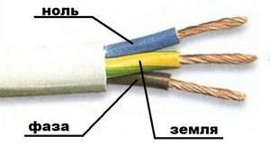
Earthing cable yellow-green. Correct connection of wires phase zero earth
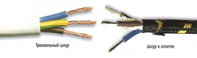
The vast majority of cables different colors lived insulation. This was done in accordance with GOST R 50462-2009, which sets the l n marking standard in electrics (phase and zero wires in electrical installations). Compliance with this rule guarantees fast and safe work masters at the big industrial facility, and also allows you to avoid electrical injury during self-repair.
Variety of colors for electrical cable insulation
The color coding of wires is diverse and varies greatly for grounding, phase and neutral conductors. To avoid confusion PUE requirements regulate what color of the ground wire to use in the power panel, what colors must be used for zero and phase.
If installation work carried out by a highly qualified electrician who knows modern standards for working with electrical wires, you do not have to resort to using an indicator screwdriver or a multimeter. The purpose of each cable core is deciphered by knowing its color designation.
Ground wire color
From 01/01/2011, the color of the ground (or neutral) conductor can only be yellow-green. This color marking of wires is also observed when drawing up diagrams on which such cores are signed in Latin letters PE. Not always on cables, the coloring of one of the cores is intended for grounding - usually it is done if there are three, five or more cores in the cable.
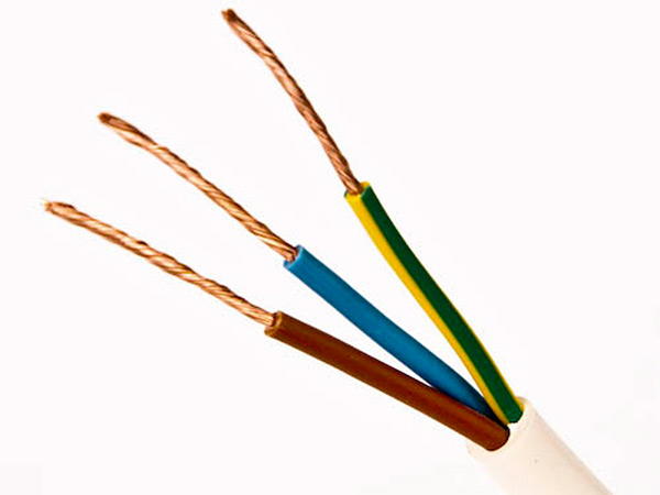
PEN-wires with combined "ground" and "zero" deserve special attention. Connections of this type are still often found in old buildings, in which electrification was carried out according to outdated standards and has not yet been updated. If the cable was laid according to the rules, then Blue colour insulation, and yellow-green cambrics were put on the tips and joints. Although, you can also find the color of the ground wire (grounding) exactly the opposite - yellow-green with blue tips.
The ground and neutral conductors may differ in thickness, often it is thinner than the phase ones, especially on cables that are used to connect portable devices.
Protective grounding is mandatory when laying lines in residential and industrial premises and is regulated by the PUE and GOST 18714-81 standards. The zero ground wire should have as little resistance as possible, the same applies to the ground loop. If all installation work is done correctly, then grounding will be a reliable protector of human life and health in the event of a power line malfunction. As a result, the correct marking of cables for grounding is critical, and grounding should not be used at all. All new houses are wired according to the new rules, and the old ones are queued for replacement.
Colors for neutral wire

For "zero" (or zero working contact), only certain wire colors are used, also strictly defined by electrical standards. It can be blue, light blue or blue with a white stripe, regardless of the number of cores in the cable: a three-core wire in this regard will not differ in any way from a five-core wire or with an even greater number of conductors. In electrical circuits, “zero” corresponds to the Latin letter N - it participates in closing the power supply circuit, and in circuits it can be read as “minus” (phase, respectively, is “plus”).
Colors for phase conductors
These electrical wires require special care and "respectful" handling, as they are current-carrying, and careless contact can cause severe electric shock. The color marking of wires for connecting the phase is quite diverse - you cannot use only colors adjacent to blue, yellow and green. To some extent, it is much more convenient to remember what the color of the phase wire can be - NOT blue or blue, NOT yellow or green.
On electrical diagrams, the phase is denoted by the Latin letter L. The same marking is used on wires if color marking is not used on them. If the cable is designed to connect three phases, then the phase conductors are marked with the letter L with a number. For example, to create a diagram for three-phase network 380 V used L1, L2, L3. Even in electrics, an alternative designation is accepted: A, B, C.
Before starting work, you need to decide how the combination of wires will look in color and strictly adhere to the chosen color.
If this question was thought out at the stage preparatory work and taken into account when drawing up wiring diagrams, you should purchase required amount cables with conductors of the required colors. If nevertheless desired wire is over, you can manually mark the cores:
- ordinary cambric;
- shrink tubes;
- tape.
About wire color marking standards in Europe and Russia, see also in this video:
Manual color marking
It is used in cases where during installation it is necessary to use wires with conductors of the same color. It also often happens when working in old houses, in which the wiring was done long before the advent of standards.

Experienced electricians, so that there is no confusion during further maintenance of the electrical circuit, used kits that allow you to mark the phase wires. This is allowed and modern rules, because some cables are made without color-letter designations. The place of use of manual marking is regulated by the norms of the PUE, GOST and generally accepted recommendations. It is attached to the ends of the conductor, where it connects to the bus.
Marking two-wire wires
If the cable is already connected to the network, then to search phase wires in electrics use a special indicator screwdriver- in its case there is an LED that glows when the sting of the device touches the phase.
True, it will be effective only for two-wire wires, because if there are several phases, then it will not be able to determine where which indicator is. In this case, you will have to disconnect the wires and use a continuity.

Standards do not oblige to make such markings on electrical conductors along their entire length. It is allowed to mark it only at the joints and connections of the necessary contacts. Therefore, if it becomes necessary to apply labels on electrical cables without designations, you need to purchase materials in advance for marking them manually.
The number of colors used depends on the scheme used, but the main recommendation is still there - it is desirable to use colors that exclude the possibility of confusion. Those. do not use blue, yellow or green labels for phase wires. IN single-phase network, for example, the phase is usually indicated in red.
Three-core wire marking
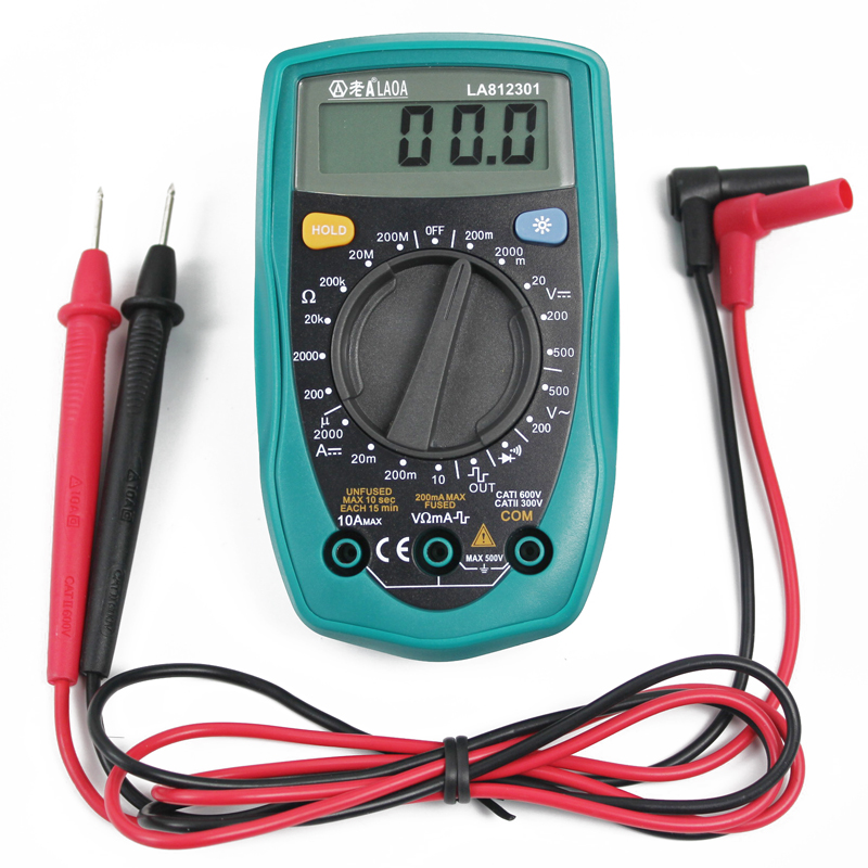
If you need to determine the phase, zero and ground in three-wire wires, then you can try to do this with a multimeter. The device is set to measure AC voltage, and then gently touch the phase with the probes (it can also be found with an indicator screwdriver) and in series the two remaining wires. Next, you should remember the indicators and compare them with each other - the “phase-zero” combination usually shows a greater voltage than “phase-ground”.
When the phase, zero and earth are determined, then marking can be applied. According to the rules, a yellow-green colored wire is used for grounding, or rather a core with such a color, so it is marked with electrical tape of suitable colors. Zero is marked, respectively, with blue electrical tape, and the phase is any other.
If, during preventive work, it turned out that the marking was outdated, it is not necessary to change the cables. Replacement, in accordance with modern standards, is subject only to electrical equipment that has failed.
As a result
Proper wiring is a must. quality installation electrical wiring during work of any complexity. It greatly facilitates both the installation itself and the subsequent maintenance of the electrical network. In order for electricians to “speak the same language”, mandatory standards for color-letter marking have been created, which are similar to each other even in different countries. In accordance with them, L is the designation of the phase, and N is zero.
The color marking of wires is far from being an advertising "chip" of manufacturers, as some novice electricians believe. This special designation, which allows the electrician to determine zero, ground and phase without the use of additional measuring instruments.
If the contacts are connected incorrectly, unpleasant consequences can occur in the form of short circuit and electric shock to humans.
The main purpose of color marking is to reduce the time for connecting contacts and create safe conditions during electrical work. On this moment, in accordance with the PUE and European standards, each core has its own clearly defined color.
About what color is neutral wire, grounding and phase, we'll talk.
Ground wire
By standards, the insulation of the "earth" is painted in a yellow-green hue. Some manufacturers apply yellow-green stripes to the ground conductor in the longitudinal and transverse directions. Rarely, but still found, shells are pure green or pure yellow.
On electrical circuits, "ground" is denoted by two Latin letters "PE". Grounding is often called zero protection, but this is not a working zero, not to be confused.

Neutral wire
Both in a single-phase electrical network and in a three-phase one, the neutral is painted in blue or blue. On the wiring diagram, zero is indicated by the Latin letter "N". Neutral is also called zero or neutral working contact.

phase wire
This wire, depending on the manufacturer, is marked with the following colors:
- white;
- turquoise;
- black;
- brown;
- pink;
- red;
- violet;
- orange.
The most common phase colors are black, white and brown.
Despite its apparent simplicity, color coding has a number of features that raise the following questions for beginners:
1.What is PEN?
2. How to determine the phase, grounding and zero if the insulation has a non-standard color or is completely colorless?
Let's deal with each point.
What is PEN?
Today's outdated grounding system type TN-C involves combining ground and neutral. Its main advantage is the speed of electrical work. The disadvantage of TN-C is the high probability of electric shock during wiring in an apartment or house.
The main color for designating the combined wire is yellow-green, but at the ends of the insulation there is a blue color characteristic of the neutral wire.
On the wiring diagram, such a contact is indicated by three Latin letters "PEN".

How to find phase, ground and zero?
There are cases when, when repairing a household electrical network, it turns out that all conductors have the same color. In this case, how to determine which wire is which.
In a single-phase network, where there are only two cores, without grounding, you just need to have a special indicator screwdriver with you. First you need to turn off the electricity at the switchboard. Then the wires are stripped and bred to the sides. Now we turn on the electricity again and alternately bring the indicator to each of the wires. If, upon contact, the light on the screwdriver lights up, then this is a phase, and the second core, therefore, zero.

If electrical network three-phase, then you need more sophisticated equipment - a multimeter with measuring probes. First, set the device to a value above 220 volts. We fix one probe in phase, and the second we determine grounding and zero. Upon contact with zero, the tester should show a voltage of 220 volts. The ground wire will show a slightly lower voltage.
If not at hand indicator screwdriver or a multitester, then you can determine the ownership of the wire by insulation. The important thing to know here is that the blue shell is always neutral. Even in the most non-standard markings, its color does not change. The other two cores are more difficult to install.
The first way is based on associations. For example, you have a colored and white or black contact in front of you. Usually the earth is indicated in white or black. Therefore, the remaining wire is a phase.
The second way. We discard the neutral again. Left red and black. According to the PUE, white insulation is a phase. Then the red conductor is ground.
In circuits with direct current, the color marking of minus and plus is represented by black and red insulation, respectively. In a three-phase transformer network, each phase is painted in an individual color:
- A-yellow;
- B-green;
- S-red.
Zero, as always, is blue, and ground is yellow-green. In cables designed for a voltage of 380 volts, the wires are designated as follows:
- A-white;
- B-black;
- S-red.
The protective and neutral conductors do not differ in marking from the previous version.
We designate the wires ourselves
In the absence of a visual indication, after repair work you need to specify the ownership of the wires yourself. For this, a bright insulating tape or heat shrink tubing.
According to GOST, the marking of the cores must be carried out at the ends of the conductors - at the points of their contact with the bus.

Such notes will greatly facilitate future repairs and maintenance.
The wires in the electrical wiring are color-coded, which allows the electrician to quickly find zero, phase and ground. If these contacts are not connected to each other correctly, a short circuit may occur, and in some cases a person is struck electricity. That's why color marking wire creates safe conditions for electrical work, and in addition, significantly reduces the time of searching and connecting contacts. Currently, according to the rules for the installation of electrical installations (PUE) and the necessary European standards, each wire must have its own specific color.
Specific colors in electrics are not chosen by chance. Colored wiring is necessary for safe electrical work to avoid short circuits and electric shock. Former conductor color was black or white, as a result, it brought great inconvenience to electricians. When disconnecting, it was necessary to supply power to the conductors, after which zero and phase were determined using the control. The use of coloring took all that pain away because everything became very clear.
Color marking is almost always applied along the entire length of the conductor. It helps to establish the purpose of each conductor to a specific group in order to facilitate their switching. There are three types of wires in an electrician: phase, zero and ground.
What does the ground and zero wire look like
According to the PUE, earth wire has the following colors:
- yellow-green;
- yellow;
- green.
You should be aware that manufacturers also apply yellow-green stripes to such a conductor in the longitudinal and transverse directions. On wiring diagram grounding is indicated by the Latin letters "PE". Quite often, grounding is called zero protection, and it should not be confused with zero working.
In a single-phase and three-phase electrical network, the wire zero is usually indicated in blue or blue-white color. On the electrical circuit, zero is indicated by the Latin letter "N". Zero is also called a neutral or zero working contact.
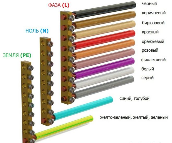
Phase wire marking (L) is presented in the following colors:
But most often the phase conductor has brown, white and black color.
How to distinguish zero and "ground"
Zero differs from grounding in that an electric current flows through it during the connection of the load, and the “ground” is used to protect against electric shock, which does not flow through this conductor, and is connected to the instrument cases.
Wires "ground" and zero can be distinguished in the following ways:
- Using an ohmmeter, measure the resistance on the ground conductor (which usually does not exceed 4 ohms). Before doing this, make sure that there is no voltage between the measuring points.
- Using a voltmeter, measure the voltage between the phase conductor and the two remaining wires in turn. In this case, the "earth" is always of great importance.
- If it is necessary to measure the voltage between "ground" and any grounded device (for example, a battery central heating or the body of the electrical panel), then the voltmeter will show absolutely nothing. And if the same method is applied to zero, a small voltage will arise.
If the color of the phase zero wires is exactly the same, then the conductors are determined using an indicator screwdriver, in which the handle is made of transparent plastic, and a diode is installed inside. Before determining the conductors, the room or house is de-energized, the wires at the ends are stripped and pulled apart, otherwise they may accidentally touch and a short circuit will occur.
After that connect electricity, take a screwdriver by the handle, and index and thumb put in contact with back side sockets. Then it is necessary to touch the bare wire with the metal end of the screwdriver and follow its reaction. If the light is on, then this is a phase, if not - zero. However, such a screwdriver will not be able to determine the conductors if there is a third wire - ground.
Conclusion
The use of color coding in electrical engineering has made life much easier for people who different reasons you need to know which wires are energized. However, you should still be careful when working with electricity, so that later there are no sad consequences.
Installation is unthinkable today electric cable without the use of wires in colored insulation. Such marking of conductors is an urgent need, since by indicating the purpose of each wire, it helps to reduce the likelihood of errors during installation and, as a result, the occurrence of a short circuit.
Before you deal with the decoding of the markings, it is recommended that you familiarize yourself with the parameters by which the wires are separated:
- Number of cores. Depending on this parameter, the cable can be used to ensure the operation of electric motors, for wiring in a house or apartment, for transmitting current in power networks.
- Conductor material. As a material in electrical most commonly used copper and aluminum or a combination of these metals.
- Insulation. Wires can be with or without insulation. Bare conductors provide a connection for power lines. Insulated are laid in places where there is a possibility of exposure to them external factors in the form of wind, water, dust or snow. Plastic, rubber, lead, paper and many other materials are used as insulation.
- Cable section. With this indicator it is possible to determine the strength of a variable or direct current , which will pass through the conductors.
- Other indicators. Resistance, power and voltage indicators are very important for network wiring and connecting various devices.
Knowing which conductors are responsible for the loads, you can correctly connect to the meter, repair the wiring, connect the oxygen sensor in the car, etc.
Wire marking for three-phase alternating current
By looking at the color marking, you can easily determine the ground, zero and phase. In modern electrical conductors each vein has an individual color. Knowing which core corresponds to which color, installation can be easily carried out. If the installation was carried out with new wiring and modern standards and the rules, then this is quite enough.
- Neutral or working zero is blue or blue-white.
- Grounding or protective zero- This is a yellow-green wire.
- The phase can be marked with all other colors, including:
- turquoise;
- orange;
- white;
- pink;
- violet;
- grey;
- red;
- brown;
- black.
Having dealt with the color of the marking, you can easily determine which wire is responsible for which function. Due to a different scheme of work, an exception may be conductors suitable for switches, switches, etc.
Color of wires plus (+) and minus (-) in DC networks
In some areas in national economy DC networks are used:
- for operational circuits of protection and power supply of automation at electrical substations;
- in electrified transport;
- in construction, industry, when storing materials.
In such networks, only two conductors are used: positive and negative buses. There is no phase or neutral conductor in them.
Marking of wires and tires for DC networks:
- red is used for positive charge wires;
- blue - for tires and wires with a negative charge;
- the middle conductor is indicated in blue.
If the DC network is created from a three-wire network (by branching), then the color of the positive conductor is the same as the positive conductor of the three-wire circuit.
Wire colors in electrical wiring
The designation of wires by color is very convenient, especially when one person does their laying and connection, and another will service and repair.
Every the color of the conductor determines its purpose in a cable according to a certain standard, which has been changed several times since the times of the USSR.
Today, conductors in electrical installations alternating current With dead-earthed neutral and voltages up to a thousand volts have a very specific marking.
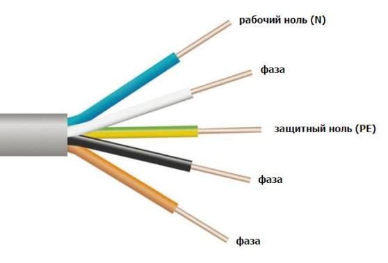
Color of zero working and zero protective wires
- Zero working conductors are indicated in blue.
- Zero protective ones are painted in yellow-green transverse or longitudinal stripes.
- Combined zero protective and zero working conductor along its entire length marked in blue with yellow-green stripes at the connection points. It may be the other way around - the entire conductor is yellow-green, and the junctions are colored blue.
This combination of colors is used only for marking zero protective pinching conductors.
How to independently determine the ground, zero and phase of the wires if there is no marking?
Quite often, situations arise when the connection is made incomprehensibly how. Some electricians, even today, may be using outdated wiring codes, leaving others to look for zero and phase with a probe and mark the conductors with the desired color with electrical tape or heat shrink tube desired color.
Phase detection with an indicator screwdriver
Inside the probe is a resistor and a lamp. When the tip of the screwdriver touches the contact and the live conductor, the circuit closes and the lamp lights up. The resistance reduces the current to a minimum, protecting against electric shock. Thus, it is quite easy to find out which phase wire is.
This is the most preferred option for determining the phase, especially since the cost of a screwdriver is quite affordable. Its main drawback is the possibility of erroneous operation. Sometimes indicator screwdriver can react to pickups and to determine the presence of tension where it is not.
Determination of ground, zero and phase using a test lamp
This method of determination is quite effective, but requires special care:
- a lamp is screwed into the cartridge, and wires with insulation removed at the ends are fixed into its terminals;
- you can also use the usual table lamp with electric plug;
- The technology is quite simple lamp wires are alternately connected to the conductors that need to be defined.
In this way, you can only find out in which conductor there is a phase. If the control lamp lights up, then this wire has a phase. If the lamp does not light, then there is no phase among the wires or there is no zero. This also cannot be ruled out.
To determine phase wire, you can connect one of the ends coming from the lamp to a known zero, and then when the second end is connected to the phase conductor, the lamp will light up. The wire that will remain and will be zero, respectively.
The way to determine the phase or zero using a lamp is good for checking the health of the wiring.
It should be remembered that when working with electrical wires requires care and caution!
Often, when necessary, home renovation electrical wiring, or a switch that, for various reasons, is out of order or simply tired, people are faced with what they don’t know what color is the ground wire in their wiring.
Ground wire color
The wire insulation in modern cables is colored in different colors, this was done in order to be able to easily and simply determine which wire is the phase, zero and ground. So, according to all standards, the ground wire in the cable is colored YELLOW-GREEN. Moreover, the coloring (marking) of this wire goes along the length of the wire, not across.
Thus, if you see an electrical cable in front of you and three wires sticking out of it, then know that:
⦁ red, brown, white, black, orange, grey, purple, pink or turquoise wires, means that this wire is phase (L);
⦁ blue or blue - this wire is zero (N);
⦁ yellow-green color of the wire means that there is a ground wire (PE) in front of you.
What regulates the color of the ground wire
Yellow green color insulation of the ground wire, also indicated in the current PUE. In accordance with clause 1.1.29. Chapter 1 Section 1 Electrical Installation Rules (PUE) 7th Edition
(approved by order of the Ministry of Energy of the Russian Federation of July 8, 2002 N 204): ... "Conductors protective earth in all electrical installations, as well as zero protective conductors in electrical installations with voltage up to 1 kV with a solidly grounded neutral, incl. tires must have letter designation PE and color designation by alternating longitudinal or transverse stripes of the same width (for tires from 15 to 100 mm) yellow and green.
Separately, it should be added that the color of any of the above wires does not guarantee that this or that wire is a phase, zero or ground. If the wiring itself was laid before you by a not quite experienced electrician (or a person who is not one at all), then the wires can be mixed up. To avoid this, wires of only one color should be connected to each other - blue with blue, white with white, yellow-green with yellow-green.
This approach will eliminate unnecessary problems in the further operation of the electrical wiring, as well as save the time you spend looking for, for example, a grounding conductor.
What color is the ground wire?
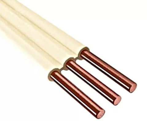
If all wires are the same color
If the wiring is made of wires with single-color insulation, such as, for example, PPV 3 × 2.5 mm, then usually the ground conductor in them is in the center. After all necessary work with this kind of wiring, color-code all of its wires. This can be done, or in any other way convenient for you. This is necessary in order to immediately see which wire is what next time.
 (1 ratings, on average: 5,00 out of 5)

