Disassemble el. How to read electrical diagrams? Analysis of a simple circuit. Disassembly with random tool
Popularity today household appliances powered by electricity is constantly growing, but minor breakdowns sometimes occur during operation. An electric stove is present on each modern kitchen– she is the heart of this room. When a kitchen assistant breaks down, many home craftsmen are interested in whether it is possible to repair an electric stove with their own hands?
Firstly, a home craftsman who decides to repair an electric stove himself must at least understand electrical appliances, know the basic fundamentals of electrical engineering and safety rules when carrying out this type of work. Secondly, you need confidence that you can carry out such complex repairs, and most importantly, find and fix them. Thirdly, it is necessary to prepare special tool.
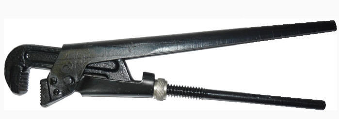
When dismantling electric stoves you will need screwdrivers for various purposes: cross or slotted, with different thicknesses, the so-called sting by specialists. You will definitely need wrenches - open-end and socket wrenches, pliers, wire cutters. For interior work in the product body you will need a soldering iron, side cutters, insulation tape and, of course, special device for measuring voltage and resistance.

The photo shows only an approximate set the necessary tool- during work, the range of tools used tends to expand significantly.
Design and main components of an electric stove
The electric stove looks very impressive - it is a complex household appliance, but quite simple, and all the main working elements are in a special heat-resistant housing, which is made of stainless steel.

The operating principle is similar to all electrical household appliances: current passing through heating elements (heating elements) heats them to a given temperature. The plate has on hob several burners, and their number varies: at least two, and the standard is 4 pieces. For example, the budget electric stove Mechta 15M has only two burners and a small oven, while the product of Belarusian engineers Hephaestus has a standard set of burners and a large oven.
The structure of the burners quite varied. The classics are burners on an enamel hob with heating elements inside, modern ones are solid ceramic surfaces with various types of heaters built into them. Let's look at the main types of burners.
- Old domestic versions are equipped with products made of cast iron, they heat up slowly and also cool down, creating a steam effect in the kitchen, but they are resistant to moisture and high temperatures.
- Tubular spirals - they are made from a hollow tube, when heated, such devices not only give off heat, but also promote the circulation of warm air inside their body, which significantly increases their operating efficiency. These products are very difficult to repair yourself. ceramic They are very simple in design, they can be easily repaired at home - a nichrome spiral is placed in special cells in a circle and secured. IN modern models Glass-ceramic solid slabs are increasingly being used - they are more durable and easy to clean.
- Halogen devices- these are special burners with a similar emitter, which are installed in different places on the hob. A stove with such burners provides fast heating, in a second, and low energy consumption, so they are the most economical, but only professional craftsmen can carry out repairs.

All models modern slabs used to transmit current to the burners power wire of a special cross-section; in addition, they are connected to regulators and thermostats, ensuring their protection from overheating.
In different models, the heating level is controlled in different ways: by manually changing the cooking mode or by special timers and alarms that monitor.
Common faults
During operation of electric stoves, users may encounter such typical malfunctions.
- Sometimes when you turn on the product, it appears burning smell- you need to turn off the stove and inspect the burners on which there could be remains of burnt food, which can be easily removed. When the smell of burnt plastic or rubber appears, you need to call a professional.
- The heating element does not heat up- this is the fault of the burner or the connecting wires, but first you need to check the controls, maybe the contact has come loose.
- Impossible tune optimal temperature heating the burner - the switch needs to be repaired.
- The burner does not heat up- if you have a spiral inside, it often ruptures due to overheating or moisture. In this case, repairing the electric stove is very simple - replace the spiral, that’s all the repair is.
- - it is necessary to ring the heating elements, it is 100% their fault, replacement is required, because they cannot be repaired.
Modern electric stoves with heating elements quite often use a cascade-type burner heating thermostat.
Power regulator
Sometimes a regulator breaks down and an identical replacement can be found. Experienced professionals advise installing triac type such a device, you just need to take it with a reserve of power and current. In some models it is installed on the same board along with the radiator. When the stove burner operates at maximum, and the heating adjustment cannot be changed, this indicates that the regulator has failed for an unknown reason - it urgently needs to be replaced.
Every user must understand that modern Appliances stuffed with electronics, each model has its own nuance of manufacturing and control, different from others - mechanical or electronic. Outside intervention without special knowledge and skills can negatively affect the delicate filling of electric stoves.
If you have a simple stove with burners on an enamel hob, then you can repair it yourself by first watching the video:


You can repair a drill yourself, the main thing is to know the causes of breakdowns and methods of “treating” them. Today we will talk about what the drill button connection diagram looks like, and we will not ignore other faults, thanks to which you will be the happy owner of a working tool.
If your tool begins to work worse, or even stops performing its direct duties, it’s time to diagnose the problems and try to deal with them. First, we check the wire for damage and the voltage in the outlet, for which you can plug in any other device - a TV or a kettle.
If you are inspecting battery-powered devices, they should be checked using a tester - in this case, the voltage indicated on the case should have a similar value to the battery voltage.
If the voltage is less, you will have to replace the batteries with new ones. If the battery is working normally, the power supply is normal, look for hardware problems. The most frequent breakdowns consider:
- Problems with engine operation;
- Brush wear;
- Problems with the button operation.
Knowing how the electric drill button is connected, you can quickly solve the problem. In addition, a problem with the operation of the drill can also arise due to the dustiness of the tool, because the drill “takes” wood, brick, and other materials. This means that you should take care to clean the device after each use - this is the only way to reduce the risk of malfunctions due to contamination of the tool. That is why, after you have carried out, immediately clean the drill.
Unfortunately, to check the functionality of the tool, a tester will not be enough for you, which is due to the fact that most of The device buttons are equipped with smooth speed control, and therefore a regular tester may give you incorrect data. In this case, you will need a special connection diagram for the drill button. Often in instruments one wire is connected to a terminal, and therefore pressing the button simultaneously leads to ringing of the terminals. If the light comes on, everything is fine with the button, but if you notice a malfunction, it’s time to replace the button.
When making a replacement, keep in mind that the circuit can be either simple or with reverse. Due to this, all work on replacing the button must be carried out exclusively according to the diagram, without adding anything “on your own”. So, the part must be suitable in size and match the power of the tool. At the same time, calculating power is a fairly simple task. We use the formula P=U*I (taking into account that the drill power is 650 W), I = 2.94 A (650/220), which means the button should be at 2.95 A.
Despite the fact that this process is quite complicated, you can do all the work yourself, following some important rules. For example, remember that opening the case may cause all parts and loose parts to simply fall out of the case. Naturally, this should be avoided, because then it will be quite difficult to assemble the device together. To do this, you can smoothly lift the cover, noting the exact location of the spare parts on paper.
The button is repaired as follows:
- First, the clamps for the casing are hooked, after which it is carefully pulled together;
- All rusted and darkened terminals are cleaned of carbon deposits, for which you can use alcohol or sandpaper;
- We reassemble the tool, making sure that all parts of the device are in place, and check the functionality of the drill - if nothing has changed, we change the part;
- We fill the speed regulator with a compound, and therefore if a part fails, we simply replace it;
- A frequent breakdown is the abrasion of the working layer under the rheostat - it’s better not to repair it, it’s just a waste of time, it’s better to buy a new one and replace it.
Many people are interested in where to get such a scheme? First of all, it should come with the instrument when you purchase it, but if there is no diagram or you have lost it, you will have to look on the Internet. After all, only with its help will you be able to carry out repairs competently, without errors. By the way, the speed control button and the reverse control button are located in different places, and therefore you will have to check them separately.
There are several reasons for damage to the armature or stator of a drill. First of all, this is illiterate operation of the device. For example, many users simply overload the tool, working without interruption. This leads to the fact that the drill motor does not have time to “rest”. The second reason lies in poor coil wire, which is often found in cheap models. That is why breakdowns of cheap tools are much more common. In this case, repairs must be carried out using specialized tools. And it will be better if you entrust this work to professional specialists.
However, if you decided to carry out the repairs on your own, you will definitely have a question - how to do everything right? As you already understand, it “suffers” from armature and stator breakdowns, and this can be checked with several signs, for example, when the tool suddenly sparks during operation. If there are no “bright” signs, you can use an ohmmeter.
The stator is changed like this:
- First, carefully disassemble the device body;
- Remove the wires and all internal parts;
- After finding out the causes of the breakdown, we replace the spare part with a new one and close the housing again.
But the drill may not work due to trivial faults - for example, due to brushes inside the motor. This means that you can’t do without repairing brushes, and this work is quite simple - you don’t even need to have special knowledge and tools. To do this, we disassemble the device, remove the brush holders from it and replace parts that are broken. By the way, there are models whose body does not need to be disassembled - you just need to remove special plugs through the installation window, after which we change the brushes.
You can purchase these parts at any hardware store; there are also some models that are sold along with a set of additional brushes. It is important that you do not wait until the brushes are completely worn out - check them from time to time. And all due to the fact that there is a risk of a gap forming between the bristles and the collector. As a result, this part will begin to overheat and eventually fall off - which means you will have to change the entire anchor, which will be much more expensive and more difficult, and it is not a fact that you will be able to solve this issue yourself.
As you can see, there are a variety of breakdowns, many of which will be within your control, others will only be within the capabilities of specialists. service centers. And to reduce the risk of such breakdowns, you need to take care of your tool, clean it after work, check the condition of the parts and brushes in order to replace them with new ones in time. However, if you see that you can’t handle it yourself, take the device to a workshop.
Household appliances for cooking are widely used by mankind, and the leader of them, perhaps, is the electric kettle. But the service life of any electrical appliance is not eternal and there comes a time when you turn on Electric kettle, but the water does not heat up.
An electric kettle is one of the simplest household electrical appliances, and in many cases it is quite easy to repair it with your own hands, even without the skills of an electrical engineer.
Operating principle and electrical circuit of the electric kettle
To repair an electric kettle, you need to know the principle of its operation. This is easy to do using an electrical diagram. Although there are many models of kettles, they are all assembled according to the same electrical circuit, regardless of appearance and capacity. There are some differences in the schemes, for example, the presence of a timer, but the basis of the scheme is still the same.

The electric kettle works as follows. Through the electrical plug, the mains voltage is supplied using a flexible cord to the XP1 contacts of the stand, on which the electric kettle is installed when heating water. At the base of the kettle there are mating contacts, which, when installed on the stand, are connected to the contacts on the stand.
Next, the current passes through thermal switch S1, which is turned on using the key on the kettle and turns off automatically when the water boils. The thermal protection switch S2 is not directly involved in the operation, it is always on and only triggers if the body overheats, if the kettle is turned on without water. From the switches, voltage is supplied to the terminals of a tubular electric heater, abbreviated as heating element. The HL lamp serves to indicate the on state.
Arrangement of electric kettle components
If the voltage of the electrical appliance differs from 220 V, for example, a 12 V car electric kettle, then you can calculate the current consumption using an online calculator.
Attention! When repairing an electric kettle and any other household electrical appliances included in household network, extreme caution should be used. Touching an unprotected part of a person’s body to live wires and live parts can cause serious damage to health, including cardiac arrest. Don't forget to unplug the electric kettle from the socket!
How to disassemble an electric kettle
For precise definition causes and elimination of the malfunction, it is necessary to remove the cover from the bottom of the electric kettle. You may encounter some difficulties when removing the cover.

Usually the bottom cover is screwed to the base of the electric kettle with self-tapping screws with slots for a Phillips screwdriver. Sometimes the heads of the screws are recessed into the lid and covered with decorative plugs, which must be removed using a sharp object to be able to unscrew the screws.

Some manufacturers to complicate the possibility self-repair of an electric kettle, all or one of the screws is installed with a slot under the shaft of a two-pronged fork type screwdriver, which is called Spanne, as in this photograph. A screwdriver with a Spanne blade is rarely available to DIYers. If you do not have such a screwdriver, you can unscrew the screw using side cutters or tweezers.

If you can’t unscrew the screw in this way, then you need to make a special screwdriver with your own hands from a screwdriver with a flat blade, making a hole in the middle for the slot profile using a needle file.

During repairs, it sometimes happens that it is impossible to unscrew a plastic screw. In this case, you can try to move the screw from its place in the direction of tightening. If it moves, it will unscrew easily.
If you can’t unscrew the screw this way, you need to heat it with a soldering iron, applying the tip to the head. When heated, the plastic around the thread of the screw will soften, and it will easily unscrew. The same technology is used to disassemble the electric kettle stand.

In some models of electric kettles, after unscrewing the screws, the lid can be easily removed. But more often it is additionally secured around the entire perimeter with latches. There are models in which the lid is held in place only by latches.
At the top of the photo there is a lid with a latch, and at the bottom the base of the electric kettle with a square hole into which the latch fits when the lid is installed. On the right side of the base, one of the kettle handle latches is caught in the frame.

To release the latches, you have to carefully insert the flat blade of a screwdriver into different places the junction of the cover and the body in search of the location of the latch.

When it is possible to remove one of the latches from the hole, the screwdriver is left in this place and the second screwdriver is used to look for the next latch located nearby. When a couple of latches are released, the rest are no longer clamped, and the cover can be easily removed. Often, removing the cover from the base is more difficult than troubleshooting.
The electric kettle does not heat water, the power indicator light is on
This behavior is the easiest way to determine the malfunction. As can be seen from the electrical diagram, the indicator light or backlight is connected directly to the terminals placed on the terminals of the heating element. Therefore, if the light is on and the kettle does not heat the water, it means that the cause of the malfunction lies in poor contact of the terminals with the terminals of the heating element or a break in the spiral inside it.
Restoring contact in slip-on terminals
After removing the lid from the base of the kettle and inspecting the connecting contacts, the cause of the breakdown became obvious. One of the contacts of the heating element was burnt, and the terminal was practically hanging in the air.

On the second terminal of the heating element, the terminal was also in poor condition, the whole thing turned black along with the contact. It’s amazing how an electric kettle could heat water before.

The terminal was completely burned out, and its further use was impossible. Although the contact on the heating element output was partially burnt, it did not require spring properties, and the remaining part after cleaning will ensure good contact.
There was no new terminal available and I had to use a used terminal. If there is nowhere to get a new terminal, then you can use the terminal from the stand, which is used to connect the ground wire (yellow-green wire). In the vast majority of apartments, the electrical wiring does not have a grounding conductor, and removing this terminal will not affect the operation of the kettle.

Before using the old terminal, it must be freed from the wires pressed into it. To do this, you need to clamp the terminal as in the photo with small pliers and a faceted awl, pressing and rotating it, push the antennae apart. The remaining wires will fall out and the terminal will be ready for reuse.

In the photo on the left you can see two wires that were pressed into the terminal. By thick stranded wire The supply voltage is supplied, and through a thin single-core it is supplied to a neon light bulb or water lighting system. These wires need to be inserted into the terminal shank and crimped with pliers, after which the terminal will be ready for connection to the heating element.

In the next step, you need to clean the contact on the terminal of the heating element on both sides until it shines using fine sandpaper. After this, all that remains is to put the terminal on this contact, and reliable electrical contact will be ensured.

After removing the terminal from the second contact, it turned out that both the terminal itself and the contact on the heating element were in good condition, only covered with oxide. After removing the black deposit from the contact using sandpaper, it became as good as new. Before attaching the terminal for better contact it was slightly squeezed by the pliers. To remove oxides from the internal contacting surfaces of the terminal, it must be put on and removed several times onto the flat contact of the heating element.
At this point the repair can be considered complete. All that remains is, without replacing the bottom cover, pour water into the kettle to the minimum level and check its functionality. If the kettle does not heat the water, then most likely the heating element coil is broken, but there may be other reasons. In order to continue troubleshooting, you must first check the serviceability of the heating element. It is impossible to replace the heating element in an electric kettle, since it is welded to its base. This kettle cannot be repaired.
Restoring welded contacts
A backlit glass electric kettle, model Polaris PWK 1719CGL, was repaired; when turned on, the indicator light was on, but the water did not heat up. This malfunction indicated a broken contact at the connection point of the heating element leads.

The bottom cover was easily removed after unscrewing three screws. I liked the build quality. The assumption was confirmed; in this model, the connection to the electrical circuit was not made traditional way using slip-on terminals, and by spot welding a flat brass wire directly to the terminal of the heating element, one of which has come off. Obviously, due to a technology violation, the conductor was poorly welded.

A slight mechanical impact with your hand on the second flat wire also caused it to fall off. Flat conductors were connected to the kettle's electrical circuit using slip-on terminals. They were removed and the wires were brought under the heating element terminals from below, as shown in the photo.


To ensure reliable contact of flat conductors with the terminals, they were pressed using metal strips with screws. The strips were taken from a Soviet power plug (the power cord was pressed against them) and a socket. When installing the planks, you need to make sure that they do not touch metal case teapot.

Checking the electric kettle showed excellent performance. The boiling water was beautifully illuminated with blue light thanks to LED backlight. I liked the design of the kettle, as well as the build quality. It’s a pity that the welding of the wires with the heating element leads turned out to be of poor quality. After the described repair, the electric kettle has been serving without fail for several years.
The electric kettle does not heat water, the power indicator does not light up
Like any other electrical appliance, an electric kettle is connected to the electrical network using a C6 type electrical plug, and the first thing to do if the kettle does not heat water is to make sure by external inspection that the plug is working and there is voltage in the socket. You can check the outlet by connecting any electrical appliance to it, for example, a table lamp.
Repair of the contact group of an electric kettle with a stand
Since voltage is supplied to the electric kettle through the stand by touching its contacts with the contacts of the current collector, it is necessary to check the contact pairs by external inspection for burning. A sign of contact failure in a contact pair appears at an early stage, and is manifested in the need to rotate the kettle on the stand so that it begins to heat the water. To prevent more serious consequences, you must immediately clean the contacts from carbon deposits.

To check, you need to turn the kettle over and inspect the condition of the slip rings. In the photo of this kettle, the inner ring on the left side is oxidized and burned out by several millimeters. To restore the contacted surface, it is enough to clean it until it shines with sandpaper. The ring contact has become poor due to insufficient pressure and oxidation of the contact located in the stand.

The flat contact plates in the contact assembly of the stand are secured with screws or hooks. To remove a plate secured with hooks, you must first remove the plastic insert with a screwdriver, and then, using an awl to pick up the hook, remove the plate.

After removing the cover from the stand and removing the contact plate from which current was supplied to the burnt ring, it became obvious that the end of the plate had bent and the contact pad was severely burned. Although the contact plate itself darkened a little due to heating, it did not lose its springy properties. After restoring the shape of the plate and sanding the surface of the contact pad, the plate was installed in its original place.

After installing the contact plate, before screwing the bottom onto the stand, you need to attach it to the bottom of the kettle and make sure that the contact plate moves a couple of millimeters, the contact fits in the center and does not cling to the walls of the stand. If everything is so, then you can screw the bottom to the stand and test the kettle after repair by boiling water in it.

But you're not always so lucky. There are contacts that are burnt to such an extent that stripping and straightening the plate no longer helps and you have to replace part of the plate with a new one. The photo on the left shows a contact that has burned almost to the ground. To replace, you need to cut off the plate with the contact to the first bend, clean the surface of the remaining plate until shiny with sandpaper and tin it with solder.

If you have an old electric kettle and the contacts in the stand are in good condition, then you can use them for repairs. A new replacement plate can also be taken from any powerful relay, for example RPU. There are even relays with silver contacts.

The plate is bitten off from the relay required length, bent and tinned with solder. Next, the prepared contact plate is pressed against the pre-tinned stand plate, and the assembly is heated with a soldering iron. As a result, the contact element of the stand becomes no worse than new.

After installing the contacts in the stand, it is necessary, as after the previous repair, to check the accuracy of their positioning and freedom of movement. The photo shows a stand in which both contacts were replaced by soldering.
Repairing the electric kettle switch button
Another malfunction of electric kettles that I have encountered is the failure of the power control button into the handle.

The switch may not work due to a failure of the switching mechanism or a broken key, which is what happened with the kettle that I received for repair.

An autopsy showed that one of the axes with which the key is fixed in the handle body broke off. As you can see in the photo, the left axis is missing. It immediately seems that it is impossible to repair the key, but if you think about it, you can often find a way to restore the broken plastic part.

For repairs, a brace was bent from copper wire with a diameter of 2 mm, shown in the photograph. The bracket can be made from aluminum wire or even a nail. The diameter is selected based on the diameter of the axis seat in the kettle handle.


After the plastic hardened, the key was installed in the handle. The test showed that the button began to work no worse than before the breakdown. The electric kettle has been working flawlessly for over a year during daily use.
Electric kettle switch repair
The switch in an electric kettle is placed on the handle or at the base. The switch may not work due to burnt contacts, oxidation of the bimetallic disk (when water boils, water vapor enters it and over time the disk may rust), weakening of the flat spring, or wear of plastic parts.

The photo shows the electric kettle switch taken out of the handle. He has small sizes and works exactly on the same principle as any wall switch. The only difference is that it can automatically turn off when the water boils.
By the way, the switch is a complete independent product and can be used for emergency shutdown of any electrical appliance when the temperature in the controlled area reaches more than 100°C.

Two stable switch positions are provided by a flat, arc-curved spring. In the photo on the left, the kettle switch is in the upper off position. On the right picture in the lower position when the electric kettle is turned on in water heating mode. The switch motor is connected to the contacts and thus, when transitioning from one stable state to another, closes or opens the contacts, thus turning the kettle on or off.
If the switch key does not lock, then the flat spring is to blame. It may lose elasticity or pop out. To restore the operation of the switch, it is enough to remove the flat spring and slightly increase the radius of its arc (straighten it).

A bimetallic disk is installed at the bottom of the switch. When heated by steam, the disk tongue moves upward, presses on the engine through the pusher and it moves to the upper stable position, opens the contacts, thereby turning off the power supply to the heating element.
Another malfunction that occurs in electric kettles is burnout of contacts in the switch. Contacts can be placed directly next to the power key or at a distance from it. In this case, the key is connected to the contacts using plastic rods.

In the photo on the left are the thermal protection contacts; they practically do not work and are always in perfect condition. On the right are the switch contacts, which open frequently and therefore always burn out. To clean them, you need to apply a strip of sandpaper to a narrow tool, for example, to the flat blade of a screwdriver, and remove the carbon deposits using a reciprocating motion. You can also use a needle file.
Switches are installed in the handles of some models of electric kettles. closed type and to clean the contacts it must be disassembled.

To disassemble, you need to unscrew one screw and remove the switch from the handle. Next, press in the two small clips that are located on the sides of the switch and pull the part with the contacts out of the housing by the wires. The contacts will become accessible, and all that remains is to clean them in the manner described above. When disassembling, you should not lose the small pusher that connects the bimetallic plate to the moving part. Without it, the kettle will not turn off.
How to fix a water leak from an electric kettle
When repairing electric kettles, I had to deal with their leakage in the following places:
- at the junction of the measuring window with the body (repair is not advisable, since sealing the crack with any adhesive composition gives a short effect);
- from a crack in a plastic case (cannot be repaired at home);
- at the junction of the metal disk bottom with the kettle flask.

Therefore, when purchasing a new electric kettle, to replace one that had failed due to a cracked body, I purchased a kettle with a glass bulb. I hoped that the electric kettle would never give an unstoppable leak, since the glass body, if handled carefully, is practically eternal, and the leak that arose was at the junction of the glass and metal base can be successfully eliminated.
After several years of operation of the glass electric kettle, water began to appear on its contact pad after boiling water and dripped from the bottom. After each boiling, the puddle of water on the platform became larger, and drops from the bottom of the kettle began to drip more often. I had to start repairing it.
To determine the location of the water leak, I had to unscrew two self-tapping screws in the upper part of the handle and three self-tapping screws holding bottom part, disassemble the electric kettle.

After disconnecting the bottom, to continue the repair, all that remains is to remove the plug terminals from the contacts of the heating element and the overheating protection system. To avoid problems during assembly, before removing the terminals, you should remember or sketch which of the terminals was put on which of the contacts.

The glass flask was secured to the bottom using silicone sealant. Upon careful examination of the joint, it was discovered that at the factory, as a result of a violation of the gluing technology, air bubbles had formed in several places in the silicone seam. Over time, water began to flow through one of them.
At first I wanted to seal only the water leaks with silicone, but I was not sure that the leak would not appear in a new place. Therefore, it was decided to detach the glass flask from the bottom and glue them together again.
Using a knife blade, the silicone was cut to the maximum possible depth, both along the internal seam and with outside. After this, the glass flask was separated from the bottom with little effort.

Next, the remaining old silicone was completely removed from the mating surfaces using a knife, and then the bonded surfaces were degreased with a solvent (acetone or alcohol will do). If you don’t have a solvent on hand, you can wash the surfaces hot water With baking soda or laundry soap, and be sure to dry before gluing. In addition, the surface of the metal bottom was cleaned to a shine using sandpaper.

The bottom of the kettle is made of stainless steel, which was tested using a neodymium magnet - it was not attracted to the bottom. But to my surprise, in the place where there was a leak, a hole appeared, shown in the photograph. How a hole could form in stainless steel remains a mystery to me; perhaps it is a manufacturing defect.

A hole formed in the lower part of the interface between the glass bulb and the bottom and would be closed with sealant when gluing. But I decided to use an electric soldering iron to close the hole with soft solder.
Selecting a sealant for gluing
The surfaces of the electric kettle parts are prepared for gluing and it is time to select a sealant that should be harmless to human body, withstand temperatures up to +180°C and be elastic. Silicone sealants fully comply with the requirements.
The best of them is food-grade silicone adhesive-sealant RTV 118 Q from an American manufacturer, which can withstand temperatures up to +260°C. But the price of an 82 ml tube of this sealant is comparable to the cost of a new electric kettle.
Available on the market silicone sealant Russian manufacturer VGO-1, which is also designed for sealing joints of hot and cold water supply pipes, withstanding temperatures up to +260°C. It is packaged in 300 ml tubes, but is also expensive and costs half the price of a kettle. To seal an electric kettle you need no more than 20 ml of silicone, so it is economically feasible to purchase a VGO-1 tube if you plan to use it for other work.
When choosing a silicone sealant, a reasonable question arose. Do manufacturers of electric kettles, and all of them are made regardless of the brand in China, use expensive food grade silicone? The answer is obvious; they use the cheapest sealant for sealing. Therefore, I came to the conclusion that the simplest silicone sealant, which does not contain any additives, is quite suitable. After boiling the water several times, even if the sealant contains contraindicated substances, they will all dissolve in the water and the silicone will become safe for the human body.

I had a universal construction silicone sealant on hand, Soudal, which I decided to use. It contains no additives and the sealant can withstand temperatures up to +180°C, which is quite sufficient for the heat resistance of the joint.
Gluing parts of an electric kettle
All that remains is to take the most important step - fill the bottom groove around the entire circumference with silicone sealant and insert a glass flask into it. Before applying sealant, surfaces must be degreased with alcohol or solvent.

The bottom area mating with the glass bulb was large, so after applying a strip of sealant I had to smear it with a screwdriver blade.

The glass flask was inserted into the groove in the bottom. The excess silicone squeezed out by the flask was removed using a rag soaked in a soap solution. Then stitches to give beautiful view, aligned with a finger dipped in soapy water. The picture shows the result of the work.
Checking the tightness of the connection of the kettle parts
Silicone in bulk usually hardens at room temperature at a rate of 2 mm per day. Taking into account the fact that the depth of the seam in the glued electric kettle was about 10 mm, we had to put it aside for a week, and only then carry out tests.

For testing, the electric kettle was connected to the power supply in disassembled form, directly, without a protection and control system. To do this, terminals were put on the ends of the cord with a plug, which were then put directly on the contacts of the heating element. The kettle was installed in working position, water is poured into it and then the plug is inserted into the socket. It is unacceptable to leave the electric kettle unattended with this switching circuit.
According to the scheme, all Soviet electric kettles were previously connected directly and you had to wait until the water boiled and turn them off manually by removing the plug from the socket.

A few minutes later the water began to boil. There were no traces of water leaks; the silicone sealant reliably sealed the junction of the parts. To prevent accidental leakage into the water from the silicone seam. harmful impurities, after assembling the kettle, three portions of water were boiled in it and completely replaced.
Attention! It is unacceptable to pour cold water into any heated electric kettle immediately after completely draining the boiled water from it. Due to thermal shock, microcracks may appear in the body of the kettle, from which water will begin to leak over time.
I note that this Glass teapot After the repair described above, it has been serving flawlessly for more than three years. I didn't even have to clean the contacts.
How to clean an electric kettle from rust
Over time due to rusty metal water pipes, despite the transparency of the water flowing from the tap and even its subsequent filtration, a coating of rust forms on the inner surface of the electric kettle. Many people don’t like it, and it clearly doesn’t bring health benefits.

The simplest and safe means rust removal is lemon acid, which is sold in any grocery store.

To remove rust, fill the electric kettle at least half full with water and pour one packet of citric acid into it.

Next, turn on the kettle and bring the water to a boil. Rusty marks can be removed from the top edges and lid using a brush dipped in boiling water. Water turns brown after boiling. If there are several kettles in the house, then water can be poured into each of them and boiled again.

After boiling, let the kettle cool, drain the rusty water and rinse clean water. As you can see in the photo, the electric kettle began to look like new, citric acid completely dissolved the rust.
As you can see, repairing an electric kettle with your own hands is not at all difficult and, if desired, any home craftsman can do it.

Household power tools are now in the arsenal of any home handyman. Every owner is interested in long-term, reliable operation their mechanisms. To do this, they must be handled with care and cared for.
The operating rules for each model are specified in the factory instructions. They must be read and followed.
But, I would like to draw your attention to the fact that after a certain amount of time, any power tool needs a preventive inspection not from the outside, but from the inside.
After all, it is based on commutator motors powered by AC voltage 220 volt. They transmit electricity due to the mechanism of graphite brushes, which constantly rub, are prone to wear, and require replacement over time.
A description of these structures has already been given in articles on the site about the device:
Let's take a closer look at the question: how to disassemble a DWT electric drill for internal inspection or repair. The same principles apply to any other commutator electrified tool.
All disassembly work is carried out with the power cord disconnected, when even accidental supply of voltage to the mechanism is excluded.
Carry out the first independent disassembly with your own hands and internal inspection under the supervision of an experienced technician. Unskilled independent work may cause more harm than good.
Necessary tools
Manufacturers of electrified tools often produce their products, the covers of which are fastened uniformly with screws with countersunk head. The slots on it are arranged crosswise or in another shape. Moreover, they choose their own angle of insertion of the screwdriver blade.

Due to this technique, their mounting screws seem to be similar in appearance, but differ from the fasteners. used by other companies require the use of special tools.
A home craftsman who performs DIY repairs of such devices has to purchase a set of tools with a large and varied number of removable heads.
When conducting an internal inspection, in addition to screwdrivers, you will need a multimeter or a simple electrician to check the integrity electrical wires and quality of connecting contacts.
Cases from practice
Disassembly with random tool
Certain craftsmen do not attach importance to the way the screwdriver slots fit into the grooves of the head and work with any tools that come to hand. Even ordinary flat blades are inserted into the cross-shaped slots, and the screw is turned out by creating great forces.
Is not correct method. It creates malfunctions and does not always allow for tight screwing force.
Example of screw head damage
A neighbor's DWT electric drill switch is stuck. When the plug was plugged into the socket, it began to work immediately, and the rotation could only be stopped by disconnecting the power cable.
The neighbor has sufficient knowledge and skills to repair such mechanisms, but a limited set of tools. Without particularly caring about the quality of fit of the edges of the screwdriver, he set about disassembling it. I successfully removed five out of eight screws, but failed to remove three. Moreover, on one he managed to tear off the internal edges.
He brought me a drill in a semi-disassembled state. I show it with a photo.

In the bottom photo close-up the shape of the tip of its screwdriver and the cut of the edges of the screw due to the application of a large rotating force and a small contact area are visible.

I picked up a screwdriver from my kit and unscrewed the screw. For clarity, I show both tips in the picture on the right. Compare the edges visually.

Drill disassembly sequence
The body of a modern commutator tool consists of two covers, which are tightened with mounting screws located on one side.

There are no screw heads on the opposite cover. There are only internal nuts. I showed this with a photo of my drill. By the way, pay attention to the way the power cable for storing power tools is laid with a rubber ring cut from an old car inner tube.
For me it is convenient: simple and compact.

The sequence of unscrewing the screws does not play a special role, but when disassembling I recommend using digital camera. It allows you to record all the design features and carry out assembly in the reverse order.
Internal inspection
For clarity, I showed a photograph of a DWT electric drill with the cover removed after disassembly, and highlighted with arrows in general terms main structural components requiring visual analysis.

Performing an inspection internal parts drills should be completed with electrical testing of wires and contacts.
Checking the condition of mechanical components
Inspection of the brush mechanism during disassembly
Pay attention first of all to the condition of the motor brushes, commutator plates, and the quality of the varnish insulating surface of the wires on the winding. Showed photographs of the entire mechanism with different angles.

Traces of minor dirt are visible, but they fully comply with the standards of a working tool and do not require special intervention. The brushes and commutator plates are in good condition.
Inspection of the kinematic parts of the impact mechanism
Pay attention to:
- condition of gear surfaces;
- wear of the mechanism teeth;
- shaft alignment;
- quality of bearings;
- presence of lubricant.
The photograph does not reveal any such defects that affect the performance of the drill.

Inspecting the condition of the controls
An electric drill should work comfortably in all modes:
- ensuring rotation of the drill in both directions with a reverse function;
- knocking out holes in striking mode.

The drill that was brought to me was missing the button head, which means that it was not fully controlled. The bottom picture shows the regulator from the reverse side with the reverse control lever removed.
By the way, on this drill the regulator turned out to be one-piece and not composite. I was not able to disassemble its body and examine the insides. Therefore, the reason for the bypassing of the output contact remained unclear.
With this design, in case of such a breakdown, the only way out is to buy a new regulator unit and replace the old one, which is what I recommended to my neighbor. Previously, it was possible to get to the seven-pointer, the adjusting potentiometer and the return springs.
Interference Filter Inspection
An interference suppression capacitor is connected to the regulator assembly.

Checking the fastening of wires
Cable ends from power cord with plug are connected screw clamp with head for flat screwdriver.

Checking the working body
You should also inspect and evaluate the operating condition of the drill chuck, which can be:
- quick-release design, like mine;
- with a key fastening, like on a neighbor’s drill.
In any case, the drill bit in the drill chuck must be held securely and not rotate during operation.
Electrical checks
When performing an internal inspection of the drill mechanisms, it is important to assess the condition of the electrical wires and contacts. Feeling them with your fingers and looking at them with your eyes does not always reveal defects in work. Faults can be effectively found only by passing current through the created circuits.

This operation is called dialing and is performed with an electrician’s tool: or, as shown in the photograph.
A voltage source is applied to both ends of the chain being tested, and by the activation of the indicator - the light on the continuity light or the deflection of the needle of the tester switched to ohmmeter mode, the passage of current and, accordingly, the integrity of the electrical circuit with its contacts and its readiness for operation are judged.
Assembly
All removed and disassembled drill components must be placed in their regular places. The photographs that you will view in reverse disassembly of the sequence should help with this.
At the final stage, the final fastening of all mechanisms is checked. Pay attention to:
- installing the wires carefully into the grooves and grooves of the housing;
- rotation by hand of the rotor and its components.

Then the removed cover is placed in its place, taking into account the mechanical locks and secured with fastening screws.
The drill is assembled, but you cannot immediately turn it on under load: be sure to check the quality of the assembly.
Checking the functionality of the drill after disassembly
This one is already The final stage We divide our work into three parts:
- let's look again already assembled mechanism and evaluate the rotation of the chuck with the drill by hand effort;
- we will check the operation at idle without load, listen to the rotation of the engine in all modes and analyze its controllability;
- Let's evaluate work under load in drilling, turning out screws and chiseling modes.
Only after completing these three steps can the drill be used. After all, she must answer everyone.
Post questions and comments, share the article with friends on social networks.
By providing detailed instructions with video lessons. Today I would like to pay more attention to the procedure for disassembling and assembling a water heating tank for 10-80 liters, because... There are several design options that differ from each other. The relevance of the issue is that if you remove the heating element or electronic elements incorrectly, you can break them, which, of course, is undesirable. Next, we will tell you how to disassemble a water heater with various types fastening heating elements from manufacturers such as Termex, Ariston, Gorenia, etc.
Central nut 55
If you need to disassemble a water heating tank, which has a a heating element secured with a large hex nut, as in the photo below, you can do everything quickly.
First of all, disconnect the boiler from the power supply and water supply. Before unscrewing flexible hoses, do not forget to turn off the supply cold water. After disconnecting, you need to drain the water from the water heating tank, which can be easily done using this video instruction:
Proper drainage of water
When the water is drained, you need to disassemble the bottom cover of the water heater housing, which is usually attached to 2 self-tapping screws. Under the cover you will find this large nut and the thermostat, which also needs to be removed by disconnecting the terminals that go to it. Now that you have free access to the nut, take a gas wrench No. 2 or a hub wrench 55, both can be seen in the photo:

For self-repair, you need to unscrew the heating element of the water heater counterclockwise. To make it more convenient to completely disassemble the storage boiler with your own hands, remove it from the wall and turn it upside down. When the nut is unscrewed, carefully remove the heating element by rocking it slightly from side to side. 
Since after draining the water from the tank, a small part of it may remain inside, it is recommended that when disassembling it, place a bucket under the boiler so that the residue drains into it and not onto the floor. And another piece of advice - if scale interferes with removing the heating element, use a hard non-metallic object to try to clean the hole and the heating element itself a little.
Oval flange
If you have a newer water heater, its design will be different. In this case, the heating element can be removed by unscrewing the clamping bar. The peculiarity of disassembling the body of this model is that in no case should you disassemble the boiler by turning it upside down, as the “would-be master” shows in this video:
You can't do that!
You can see for yourself that after disassembly, the heating element fell inside the container, which is coated with enamel so that the tank does not rust from the inside. Of course, when metal hits metal, both the heating element and the internal coating of the water heater can be damaged, which cannot be repaired independently.

Based on this, in order to disassemble a storage water heater with an oval flange, everything must be done without removing the boiler. The product is assembled in the reverse order.
Bolts in a circle
A fairly popular design, which is found in heaters of the Termex, Ariston, Polaris and Combustion brands, is considered to be fastening the heating element flange with bolts in a circle. These bolts can be 4, 5 or 6, depending on the model.
In order to disassemble electric boiler of this type, you need, as in previous cases, to turn off the power from the network and drain the water. After that it is better to unscrew check valve which may interfere. One of the common difficulties that arises when complete disassembly water heater with your own hands, maybe look for the screws that secure plastic cover. If you cannot find the mounting points, tear off the stickers located on this cover. Sometimes manufacturers hide the screw heads under the “nameplate”. 
Once you have removed the thermostat and all the interfering wires, you can begin to unscrew the bolts on the water heater. It is best to unscrew them with a socket wrench of the appropriate size.

How to properly remove all parts for cleaning or repair?
By the way, Ariston in some of his storage boilers This design does not use bolts, but rather, nuts that are screwed onto studs, as shown in the photo above.
In more expensive models of water heaters, when completely disassembled, you can see a bunch of wires and 2 heating elements installed next to each other. You can disassemble such a device by analogy with the previous instructions, but we recommend that you take a photo correct connection all wires before disconnecting them, so as not to get confused later and quickly assemble the tank.

A device with a dry heater can be disassembled using exactly the same method, so you should not have any questions about how to proceed.

That's all I wanted to tell you about how to disassemble a Termex, Ariston or Polaris water heater. We hope that the disassembly procedure was clear to you. If you have any questions, ask them in our
 (1 ratings, on average: 5,00 out of 5)

