Grounding strip. Installation of protective grounding
Grounding means intentional electrical connection any part of an electrical installation to earth through a grounding device.
In contrast, the accidental electrical connection of live parts of an electrical installation with grounded structural parts or directly with the ground is called an earth fault. Grounding is carried out using a grounding device consisting of a ground electrode and grounding conductors.
Grounding conductors are divided into natural and artificial. As natural grounding agents use underground water and other metal pipelines (except for pipelines with flammable or explosive gases and liquids), metal constructions buildings and structures connected to the ground, lead cable sheaths, etc. Sections of steel pipes, angle and round steel are used as artificial grounding conductors, metal plates.
In accordance with requirement of the PUE In all electrical installations with voltages up to and above 1000 V, in order to ensure the safety of people, electrical equipment housings and individual elements of electrical installations that are not energized are connected to grounding devices. In addition, the grounding device is caused by the need to ensure a certain operating mode electrical installations under normal and emergency conditions, in this case, current-carrying parts of electrical installations are connected to grounding devices. A distinction is made between protective and operational grounding, respectively.
The purpose of protective grounding is to reduce the voltage on the grounded equipment at the moment of the flow of ground fault current, as well as to equalize the voltage in the current spreading area and thereby reduce the touch and step voltage.
The resistance to the passage of electric current through ground electrodes depends on the quality and condition of the soil in which the earth electrode is located, the type of earth electrode, the depth of its placement and relative position grounding conductors.
The quality of the soil in terms of its electrical conductivity is determined by the magnitude of the resistivity. The resistivity of some soils, depending on their physical state, varies by within wide limits. Peat, river water, and rocky soils are not subject to such fluctuations.
In soils with high resistivity, special measures are resorted to to reduce its value (salts are introduced into the soil, moisturize it, etc.)
When installing the external contour of the grounding device with outside buildings, in accordance with the design, dig a trench for driving in grounding conductors and laying grounding conductors. Then the vertical grounding rods are driven in so that their upper ends protrude 200 mm from the ground from the bottom of the trench. After this, grounding conductors are laid in the trenches and welded to vertical grounding conductors.
Grounding conductors are buried in the ground using vibro- or electromagnetic plungers or an auto-drill with an attachment for driving in grounding electrodes. The grounding conductors are connected to natural grounding conductors by welding or using clamps. Wherein inner surface The clamps must be tinned, and the place where the clamp is placed on the pipe must be cleaned to a shine.
To protect against corrosion, welds located in the ground are coated with hot bitumen. In places where pipelines serving as natural grounding conductors have flanged connections to create a continuous grounding circuit, jumpers are installed.
IN Lately began to use buried grounding conductors, which in the form metal mesh made of strip steel, prepared together with grounding conductors welded to the grid in the workshops of the MZU, are laid on the bottom of the pit when laying the foundation of the buildings of workshops and substations.
When installing a grounding network inside buildings, metal structures of buildings, crane tracks, aluminum cable sheaths, galleries and others are primarily used as grounding conductors. technological metal structures, steel pipes for electrical wiring, metal pipelines, except for pipelines for flammable and explosive liquids and gases, etc. If natural grounding conductors are used, they are securely connected to the external contours of grounding devices. All contact connections are made in such a way as to ensure reliable contacts and continuity electrical circuit along the entire length. To do this, all connections of sections of metal structures are welded, bolted, rivet connections and the joints are covered with jumpers made of steel strips.
When laid openly, steel electrical wiring pipes, if they are used as grounding conductors, are securely connected using well-tightened red lead couplings or other structures that provide reliable contact (welded cuffs, screwed, with a wedge, etc.). At hidden gasket These connections are made only with red lead couplings. If there is a long section of thread at the end of the pipe - the bend - a lock nut is installed. Between the pipes and the housings of electrical equipment into which the pipes are inserted, a reliable metal connection using scratch nuts, direct welding of pipes or installation of jumpers.
Where it is not possible to use the above elements of buildings and structures as grounding conductors, a grounding network is laid from strip or round steel, respectively, with a cross-sectional area of at least 24 mm2 and a thickness of 3 mm and a diameter of at least 5 mm.
Grounding bars are laid openly along the walls at a height of 0.4-0.6 m from the floor so that they are accessible for inspection. In damp rooms and with caustic vapors, tires are laid at a distance of at least 5-10 mm from the walls. The distance between the fastening points is 0.6-1 m. The tires are fastened to the walls with dowels, which are aimed using a construction gun.
When crossing doorways tires can be laid in the floor, but they are protected from mechanical damage sections of steel pipes, as well as angle or channel steel.
All grounding artificial conductors, as well as jumpers installed at the joints of structures used as grounding conductors, are painted black (to indicate the grounding circuit). Painting in other colors is allowed in accordance with the aesthetic design of the room, but in this case it is obligatory to apply at least two stripes in places of connections and branches purple at a distance of 150 mm from each other.
Arrangement of effective grounding on the consumer side is the most important part of a set of measures to ensure reliable protection from accidental electric shock. When solving this problem Special attention is given to such a component upcoming works, such as installation of grounding devices.
Technical task
In accordance with the requirements of regulations at any energy-dependent facility, before installing the grounding loop, it is prepared technical task(TZ). It must take into account the following operating points:
- type of grounding used (single- or double-circuit, stationary or portable);
- diagram and method of laying grounding busbars;
- geometric dimensions and shape of the part of the structure immersed in the ground;
- material used for the manufacture of grounding conductors and ground electrode (steel, copper or aluminum);
- the method of connecting them (welding or jointing).
This allows you to quickly and timely carry out grounding installation work, as well as prepare documentation.
Single-circuit and double-circuit circuit
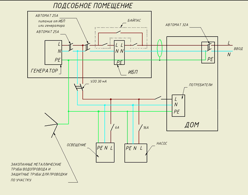
Regardless of the method of organizing power supply at an industrial or civil facility, the installation of grounding conductors and installation of protective grounding is carried out either according to a single-circuit or 2-circuit scheme.

In the first case, the grounding loop is laid only inside the building, which makes it possible to connect to it connecting busbars laid from metal parts existing installations and other electrical equipment.
Note! In the simplest situation (in living conditions, for example) may not be done at all. In this case, its function is performed by the input device or electrical cabinet main grounding bus (GZSH).
Using dual circuit system grounding, another circuit is added to the internal busbar, which is installed outside the facility. As a rule, it is performed in the form of a set of single grounding conductors distributed around the perimeter (metal rods driven into the ground or pieces of reinforcement connected to each other by a steel busbar). The resulting closed system allows you to increase the area of contact with the ground and provides Better conditions for current to flow into the soil.
External circuits complementing the internal distribution busbar are usually equipped with transformer substations, where the requirements for grounding quality are especially high. In accordance with regulatory requirements electric installation work at substations they are carried out so that the external piping elements are spaced more than one meter from the edge of the building. Metal pins or pieces of reinforcement are driven into the ground to a depth of at least 0.7 meters. In this case, the steel strip connecting them must be positioned strictly vertically (that is, placed on the “edge”).
Rules for working with portable views
The listed circuit solutions belong to the category stationary grounding, tied to a specific location. However, in a number of cases (to carry out repair work on disconnected networks, for example), it may be necessary to install temporary or portable devices, the basis of which is the principle of grounding.
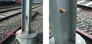
Portable structures are made in the form of bare copper core, having at one of its ends a metal pin driven into the ground, and on the other - a special copper clamp that serves for connection to the grounded bus.
Some models of portable or temporary protective devices have another clamp instead of a pin, which ensures reliable contact with the grounding structure (ground electrode).
The need for portable grounding of this class is explained by the need to prevent the appearance of dangerous voltage in the serviced area of the supply circuit, turned on by mistake or accidentally.
The rules for installing these overhead structures are strictly regulated by the current guidelines for the arrangement of grounding. Below is a list of the main points that you should pay attention to when working with them:
Removal or disassembly of the temporary grounding structure is carried out in the reverse order.
Example in railway transport
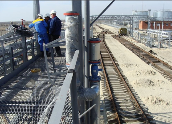
Let's consider the requirements for the installation of grounding in railway transport (stationary or traction electrical installations), instructions for which are given in the instructions TsE-191. According to this document, all operating electrical equipment must be reliably protected by connecting the grounding conductor to a special bus.
The same instructions stipulate the value of the maximum resistance of the grounding bus, at which the leakage currents are sufficient to protective devices managed to operate and turn off the emergency section of the contact network in a timely manner.
The damaged line is disconnected using special feeder switches located at the traction substation and configured to the required cut-off current (see PUE).
Special requirements are imposed on structures or units with an increased risk of exposure to contact line voltage (due to insulation breakdown or accidental contact). All this equipment must have a reliable electrical connection to the main traction or rail network.
All metal structures, including contact line supports with wires attached to insulators, are also subject to such grounding.
Connection features
When designing and installing any grounding system, the main attention should be paid to ensuring high reliability of bolted joints and welded contacts between its individual components. Since such structures are designed for long-term operation, it is necessary to minimize possible mechanical loads on them, as well as provide reliable protection metal surfaces from corrosion.
 When installing protective grounding in home wiring conditions, first of all, it is necessary to decide on the arrangement of supply lines.
The fact is that in old buildings built before 2003, regulatory requirements there was no provision for the presence of a separate grounding conductor in the supply circuit. In such houses, on the consumer side (at the distribution panel), there are only 2 wires in the supply wiring - “phase” and “neutral”.
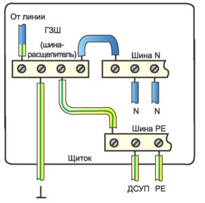 Moreover, the latter is a combined zero working (PE) and zero protective (N) conductors and, according to international standard denoted as PEN. To install grounding in such houses, the PEN conductor is deliberately split into two components, after which a separate conductor N is used as a grounding bus. It is clear that the artificial structure created in this way only partially complies with the requirements of the standards, since in apartment building It is not possible to organize re-grounding.
In houses modern buildings the supply wiring must have one more (third) core, designed specifically for connecting the grounding wire of electrical equipment and household appliances. In this case, the common conductor PEN is already divided into two separate conductors PE and N.
Manufacturing procedure for a standard ground electrode
The most common form of construction of a typical ground electrode is an isosceles triangle, the length of each side (stripes) of which is approximately 1.2 meters. In this case, steel angles with a standard size of 40x40 or 45x45 and a thickness of about 4-5 millimeters are used as its vertical components. In the absence of steel angles, pipe metal blanks having approximately the same dimensions, both in diameter and thickness, are installed (hammered) into the ground. The length of driven pipes or electrodes for grounding can be selected from 2 to 3 meters (depending on the composition of the soil).
Expert advice. To make it easier to immerse (hammer) a corner or pipe into the ground, it is recommended to cut their lower end into a cone with a grinder.
With information on acceptable sizes individual elements grounding, depending on the shape and material of the product, can be found in table 1.7.4 PUE. The figure shows the layout of the ground electrode and the composition of its elements. 
It is necessary to hammer the corners (pipes) into the ground in such a way that their ends protrude above the ground surface by about 15-20 centimeters.
After driving the pins to the required depth, they are welded around the perimeter with a steel strip 30-40 wide and 5 millimeters thick. In this case, the steel strip strapping should be located approximately half a meter deep.
Upon completion of installation, the entire grounding structure is filled with previously excavated soil, after which a wire stretched from the side of the main ground is welded to one of its corners.
It should be noted that the technology for installing an external grounding loop assumes that it is no more than 10 meters away from the building.
Monitoring the condition of elements buried in the ground is organized in accordance with a schedule approved by the relevant technical services.
There is one thing general rule performing any type of work - in order to do the work efficiently, we need to clearly understand why we are doing it and what goal we want to ultimately achieve. And to understand this, you need to understand the principle of operation of this device.
Since most people have very vague concepts about grounding, we consider it necessary to devote a few lines to the theory of grounding. Let's start with the fact that our planet Earth has a huge volume and mass and, as a result, has a huge electrical capacitance, that is, it is capable of “absorbing” very a large number of electrical energy, and without changing the electrical potential on the surface. Which, as we know, is equal to zero, that is, practically absent. This is when compared with the potential of other physical bodies on the surface of the Earth. Thunderclouds, for example, can have potentials of millions of volts relative to the Earth's surface. This high potential explains lightning - an electrical breakdown of an air mass over a length of kilometers.
It is this property of the earth’s surface (zero electric potential) is used as a starting point for electrical and electronic devices. When we talk about voltage, we mean the difference in electrical potential of the measured point in comparison with the base, zero. Without a basic reference point, the concepts of potential or voltage become meaningless. To be precise, it is quite possible that the surface of the earth does not have zero potential at all, but some other potential. But to find out, you need to compare it with something, at least with another celestial body. Since today in our practice there is nothing to compare with, we will accept the statement about the zero potential of the earth as an axiom.
But in order for the earth to “absorb” electrical energy– it must conduct current, be a conductor of current. In this regard, an interesting question is: what does the earth’s soil consist of - insulators or conductors? The answer is: the earth's soil is a mixture of insulators and conductors. For example, dry sand is an insulator. But if you moisten it with brackish water, it will become a conductor. Soil on the surface of the earth conducts electricity worse than at a depth of 10 - 20 m, firstly, because it is loose, and secondly, at such a depth there are groundwater. In winter, the surface layer freezes and turns into an insulator. This must be understood when installing grounding.
The table below shows the soil resistivity values depending on its type.
Human skin is also, essentially, an insulator. However, the human body consists of 70% water with salt solutions, and the skin has pores through which salty sweat is released, as a result the human body begins to conduct electricity. You need to know that distilled water does not conduct current and only the presence of charged particles – salt ions – in the solution makes water a conductor.
It is also necessary to understand that the resistance to current flow ( electrical resistance– R) the human body (as well as the soil of the Earth) has a much greater effect than, for example, metals. That is why we talk about dangerous and safe voltage for humans. Thus, a voltage of 24 volts on a battery is absolutely safe for humans, since according to Ohm’s law, such a voltage with a large body resistance (tens of kOhms) is not capable of causing such a current (of the order of 30 mA or more) that can cause harm. If we move on to the numbers, then on average the human body has an electrical resistance from 3 to 100 kOhm (1 kOhm = 1000 Ohm). There is a large spread in different people is explained by many factors - health, skin condition, and even depends on whether the person drank or not. It is known that during alcohol intoxication the resistance of the human body decreases, which is a good thing to remember professional electricians. And finally, we note that according to the PUE, a voltage of 42 volts is considered safe for humans, but if the voltage is higher than this value, then for protection it is necessary to use protective grounding, which we will discuss below.
What is grounding?
Grounding- this is an intentional electrical connection of an arbitrary point in the network, equipment or electrical installation with grounding devices.
Grounding device- this is a set of grounding conductors or grounding conductors.
Ground electrode- this is a set of interconnected conductive elements that are in electrical contact with the ground or soil.
There are also (according to the PUE) types of grounding according to the function performed - working (functional) and protective. In this article we will consider protective grounding and its design.
To better understand how grounding can protect a person in an accident, let’s imagine a simple and fairly common situation - on some equipment, as a result of poor contact, the conductor located under the ground burns out. phase voltage 220 volt. At the same time, it almost inevitably touches some body part inside the electrical appliance. An electrical potential of 220 volts appears on the body. If the housing is not grounded and not connected to neutral wire, then nothing happens externally, no leakage current appears, and the protection does not work. This inconspicuousness is where the danger lies. A person, approaching the device to start working, touches the body and receives an electric shock from a voltage of 220 volts.
If the body of the device is grounded - connected by a conductor to the ground, which has zero potential, then the potentials of the earth and the body will tend to equalize and a leakage current will flow through the grounding conductors. Since the grounding resistance is small enough, the current will (according to Ohm's law) be of sufficient magnitude for the protection to operate. This will definitely attract the attention of the staff (if they try to turn on the circuit breakers again, the situation will repeat) and force them to do repairs. But even if the protection does not work and a person touches a grounded body, a new branch of the current circuit is formed through the human body. As is known, when an electrical circuit is branched, the currents in the branches have a value inverse to the resistance of the branches. Let the human body have a resistance of 100,000 Ohms, and grounding - 10 Ohms. In this case, the current through the human body will be 10,000 times less than the current through the grounding circuit.
All of the above is important in order to understand that the main characteristic of grounding is its electrical resistance! It should be small! PUE recommend a number of values for various types and grounding purposes. For example, the grounding resistance for private houses when connected to the lightning protection grounding should be no more than 10 Ohms, with a conventional grounding system - no more than 30 Ohms. In a system in which the grounding is isolated from the neutral of the current source (zero) and an RCD device with an operating “current” of no more than 100 mA is used, the grounding resistance can be no more than 500 Ohms.

But this is not enough, the grounding design must be such that this small resistance value is maintained for a long time regardless of the season, be it winter or summer, and the structure itself was not destroyed by corrosion.
Grounding resistance can be reduced by increasing the contact area of the ground electrode with the ground, as well as the depth of placement of the ground electrode in the ground. Sometimes the resistance is reduced by wetting the soil near the ground electrode with a solution of salt, usually table salt, instead of deepening the ground electrode, since deepening requires greater energy and labor costs. However, such a solution cannot be considered good, since after 1-3 years the salt is eroded by precipitation. Besides brine sharply increases corrosion of the structure.
The material from which the grounding structure is made is, as a rule, ferrous metals - structural steel. The use of non-ferrous metals or stainless steel is too expensive in terms of cost due to the considerable material consumption of the structure. Therefore, steel grounding parts must be protected from corrosion. Of course, not an insulator ( paint coating), A metal coatings. It is recommended to use galvanizing or copper plating of ground electrode parts. In a zinc-steel pair, zinc, being a more electrochemically active metal, begins to deteriorate earlier than the steel base, and until the zinc coating is completely destroyed, the steel remains protected. In a copper-steel pair, everything happens the other way around: the steel begins to collapse, and until it all collapses, the copper remains intact. Hence the conclusion - when copper plating, the coating must have sufficient thickness, at least 250 microns. A copper-plated ground electrode lasts longer than a galvanized one.
When constructing grounding electrodes today, vertical grounding electrodes are most often used, for which steel pipes, rods, rolled products - angles, channels, etc. are almost always chosen. This is explained by the fact that horizontal electrodes are much more difficult to place at great depths, and at shallow depths their main characteristic - resistance - is greatly deteriorated, especially due to freezing in winter period. Well, the widespread use of pin structures is explained, accordingly, by the fact that they can be driven into the ground, unlike sheet metal, although the leaf has a large surface.
Today, the most common grounding structures are considered to be two:
1. Based on a number of short pins driven into the ground manually (with a sledgehammer) to the maximum achievable depth and connected to the ground loop with a steel strip electrically welded to the protruding ends of the pins. The required resistance value is achieved by increasing the number of pins. The exact dimensions and number of pins are determined by calculation, taking into account the type of soil, climatic factors, etc. A specific calculation method can be found on the Internet or in reference books. It should be taken into account that when using a group of pins as a grounding conductor, a factor that reduces the efficiency of operation begins to appear, such as mutual influence or “shading,” which depends on the distance between the pins. If the distance is too close, the effectiveness of grounding may be significantly reduced. Therefore, the pins must be placed at a distance no less than their length, and preferably at a greater distance. Then the decrease in efficiency will not be too noticeable.
The disadvantages of this method are the need for large area for grounding equipment, high material consumption and the need for heavy manual labor.
2. A single deep electrode, the so-called “casing pipe”, installed using a drilling machine (on a truck) to a depth of 20 - 30 meters. In terms of operating efficiency, such a ground electrode is superior to the previous one with the same total length of electrodes due to the fact that at depths of more than 5 meters the soil has several times less resistivity due to the fact that its humidity and density are much greater than those of the surface.
Disadvantages of this method - high price drilling and materials and reduced service life (5-15 years) due to corrosion in humid environments.
In conclusion we present specific example installation of grounding using the first method.
1. Initial data obtained from the calculation:
- the number of required electrodes - pieces of steel reinforcement or angles 40x40x5, 3 meters long with zinc coating - 20 pieces.
— the driving depth of the electrodes is approximately 3 meters.
2. Along the perimeter of the building along the walls at a distance of at least 1 meter, starting from the point of entry of the grounding wire to the input electrical panel, a trench is made 0.5-0.37 meters deep and 60 meters long. A trench is needed to insulate and protect the grounding conductor and connecting conductor from weather factors (rain, freezing) and mechanical damage, for example, when digging earth for a flower garden.
3. Pre-prepared electrodes, previously sharpened at one end with a grinder, are driven into the bottom of the trench at a distance of 3 meters from each other using a sledgehammer.
4. After driving the electrodes to their ends, a steel strip of 40x5 mm is welded to their ends by electric welding from the first electrode to the last. The seam is made continuous, with a 5 mm leg. To connect the grounding wire in a place next to the grounding input, the strip is brought out to the required length. The use of welding for fixing elements made of black steel is strongly recommended (PUE, clause 1.7.139).
5. Welding areas are coated for corrosion protection. bitumen varnish or anti-corrosion paint, after which the ditch is filled up.
6. Outside or inside the room, a transition is made from a steel strip to copper wires grounding using bolt clamps with washers. The clamping points and bolts are coated with paint.
Similar to the first, we will give an example of installing grounding using the second method.
1. At a distance of 3 meters from the wall of the house (for safe access of the drilling rig), a ditch is dug 0.5 - 0.7 m deep and 3 - 4 meters long.
2. The drilling rig carries out the drilling process, and then the installation of the electrode itself (for example, steel pipe diameter 100 mm, installed at a depth of 20 meters).
3. The grounding conductor is laid - a steel strip 40x5 and welded with a continuous seam (5 mm leg) to the end of the pipe.
In conclusion, we note that currently there are reports of a new method of installing a ground electrode system consisting of a composite pipe to depths of up to 20 meters by hammering the elements of the ground electrode pipe one by one with a sledgehammer.
And lastly, the resistance of the mounted grounding must be checked. For this purpose they are used special methods and devices, this cannot be done with a regular tester. How to do this can be found in reference books and articles on the Internet.
 (1 ratings, on average: 5,00 out of 5)

