Blue brown yellow green how to connect. Color of wires according to purpose: phase, zero and "ground"
Installation is unthinkable today electric cable without the use of wires in colored insulation. Such marking of conductors is an urgent need, since by indicating the purpose of each wire, it helps to reduce the likelihood of errors during installation and, as a result, the occurrence of a short circuit.
Before you deal with the decoding of the markings, it is recommended that you familiarize yourself with the parameters by which the wires are separated:

- Number of cores. Depending on this parameter, the cable can be used to ensure the operation of electric motors, for wiring in a house or apartment, for transmitting current in power networks.
- Conductor material. As a material in electrical most commonly used copper and aluminum or a combination of these metals.
- Insulation. Wires can be with or without insulation. Bare conductors provide a connection for power lines. Insulated are laid in places where there is a possibility of exposure to them external factors in the form of wind, water, dust or snow. Plastic, rubber, lead, paper and many other materials are used as insulation.
- Cable section. With this indicator it is possible to determine the strength of a variable or direct current , which will pass through the conductors.
- Other indicators. Resistance, power and voltage indicators are very important for network wiring and connecting various devices.
Knowing which conductors are responsible for the loads, you can correctly connect to the meter, repair the wiring, connect the oxygen sensor in the car, etc.
Wire marking for three-phase alternating current
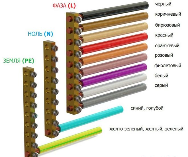
By looking at the color marking, you can easily determine the ground, zero and phase. In modern electrical conductors each vein has an individual color. Knowing which core corresponds to which color, installation can be easily carried out. If the installation was carried out with new wiring and according to modern standards and rules, then this is quite enough.
- Neutral or working zero is blue or blue-white.
- Grounding or protective zero- This is a yellow-green wire.
- The phase can be marked with all other colors, including:
- turquoise;
- orange;
- white;
- pink;
- violet;
- grey;
- red;
- brown;
- black.
Having dealt with the color of the marking, you can easily determine which wire is responsible for which function. Due to a different scheme of work, an exception may be conductors suitable for switches, switches, etc.
Color of wires plus (+) and minus (-) in DC networks
In some areas in national economy DC networks are used:
- for operational circuits of protection and power supply of automation at electrical substations;
- in electrified transport;
- in construction, industry, when storing materials.
In such networks, only two conductors are used: positive and negative buses. There is no phase or neutral conductor in them.
Marking of wires and tires for DC networks:
- red is used for positive charge wires;
- blue - for tires and wires with a negative charge;
- blue color the middle conductor is indicated.
If the DC network is created from a three-wire network (by branching), then the color of the positive conductor is the same as the positive conductor of the three-wire circuit.
Wire colors in electrical wiring
The designation of wires by color is very convenient, especially when one person does their laying and connection, and another will service and repair.
Every the color of the conductor determines its purpose in a cable according to a certain standard, which has been changed several times since the times of the USSR.
Today, conductors in electrical installations alternating current With dead-earthed neutral and voltages up to a thousand volts have a very specific marking.
Color of zero working and zero protective wires
- Zero working conductors are indicated in blue.
- Zero protective ones are painted in yellow-green transverse or longitudinal stripes.
- Combined zero protective and zero working conductor along its entire length marked in blue with yellow-green stripes at the connection points. It can be vice versa - the entire conductor is yellow-green, and the junctions are painted in Blue colour.
This combination of colors is used only for marking zero protective pinching conductors.
How to independently determine the ground, zero and phase of the wires if there is no marking?
Quite often, situations arise when the connection is made incomprehensibly how. Some electricians, even today, may be using outdated wiring codes, leaving others to look for zero and phase with a probe and mark the conductors of the desired color with electrical tape or heat shrink tubing of the desired color.
Phase detection with an indicator screwdriver
Inside the probe is a resistor and a lamp. When the tip of the screwdriver touches the contact and the live conductor, the circuit closes and the lamp lights up. The resistance reduces the current to a minimum, protecting against electric shock. Thus, it is quite easy to find out which phase wire is.
This is the most preferred option for determining the phase, especially since the cost of a screwdriver is quite affordable. Its main drawback is the possibility of erroneous operation. Sometimes indicator screwdriver can react to pickups and to determine the presence of tension where it is not.
Determination of ground, zero and phase using a test lamp
This method of determination is quite effective, but requires special care:
- a lamp is screwed into the cartridge, and wires with insulation removed at the ends are fixed into its terminals;
- you can also use the usual table lamp with electric plug;
- The technology is quite simple lamp wires are alternately connected to the conductors that need to be defined.
In this way, you can only find out in which conductor there is a phase. If the control lamp lights up, then this wire has a phase. If the lamp does not light, then there is no phase among the wires or there is no zero. This also cannot be ruled out.
To determine phase wire, you can connect one of the ends coming from the lamp to a known zero, and then when the second end is connected to the phase conductor, the lamp will light up. The wire that will remain and will be zero, respectively.
The way to determine the phase or zero using a lamp is good for checking the health of the wiring.
It should be remembered that when working with electrical wires requires care and caution!
The vast majority of cables different colors lived insulation. This was done in accordance with GOST R 50462-2009, which sets the l n marking standard in electrics (phase and zero wires in electrical installations). Compliance with this rule guarantees fast and safe work of the master on a large industrial facility, and also allows you to avoid electrical injury during self-repair.
Variety of colors for electrical cable insulation
The color coding of wires is diverse and varies greatly for grounding, phase and neutral conductors. To avoid confusion PUE requirements regulate what color of the ground wire to use in the power panel, what colors must be used for zero and phase.
If installation work carried out by a highly qualified electrician who knows modern standards for working with electrical wires, you do not have to resort to help indicator screwdriver or multimeter. The purpose of each cable core is deciphered by knowing its color designation.
Ground wire color
From 01/01/2011, the color of the ground (or neutral) conductor can only be yellow-green. This color marking of wires is also observed when drawing up diagrams on which such cores are signed in Latin letters PE. Not always on cables, the coloring of one of the cores is intended for grounding - usually it is done if there are three, five or more cores in the cable.
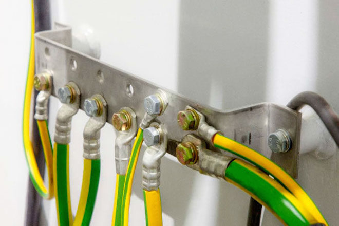
PEN-wires with combined "ground" and "zero" deserve special attention. Connections of this type are still often found in old buildings, in which electrification was carried out according to outdated standards and has not yet been updated. If the cable was laid according to the rules, then the blue color of the insulation was used, and yellow-green cambric was put on the ends and joints. Although, you can also find the color of the ground wire (grounding) exactly the opposite - yellow-green with blue tips.
The ground and neutral conductors may differ in thickness, often it is thinner than the phase ones, especially on cables that are used to connect portable devices.
Protective grounding is mandatory when laying lines in residential and industrial premises and is regulated by the PUE and GOST 18714-81 standards. The zero ground wire should have as little resistance as possible, the same applies to the ground loop. If all installation work is done correctly, then grounding will be a reliable protector of human life and health in the event of a power line malfunction. As a result, the correct marking of cables for grounding is critical, and grounding should not be used at all. All new houses are wired according to the new rules, and the old ones are queued for replacement.
Colors for neutral wire

For "zero" (or zero working contact), only certain wire colors are used, also strictly defined by electrical standards. It can be blue, light blue or blue with a white stripe, regardless of the number of cores in the cable: a three-core wire in this regard will not differ in any way from a five-core wire or with an even greater number of conductors. In electrical circuits, “zero” corresponds to the Latin letter N - it participates in closing the power supply circuit, and in circuits it can be read as “minus” (phase, respectively, is “plus”).
Colors for phase conductors
These electrical wires require special care and "respectful" handling, as they are current-carrying, and careless touch can cause severe injury. electric shock. The color marking of wires for connecting the phase is quite diverse - you cannot use only colors adjacent to blue, yellow and green. To some extent, it is much more convenient to remember what the color of the phase wire can be - NOT blue or blue, NOT yellow or green.
On electrical diagrams, the phase is denoted by the Latin letter L. The same marking is used on wires if color marking is not used on them. If the cable is designed to connect three phases, then the phase conductors are marked with the letter L with a number. For example, to draw up a diagram for a three-phase 380 V network, L1, L2, L3 were used. Even in electrics, an alternative designation is accepted: A, B, C.
Before starting work, you need to decide how the combination of wires will look in color and strictly adhere to the chosen color.
If this question was thought out at the stage preparatory work and taken into account when drawing up wiring diagrams, you should purchase required amount cables with conductors of the required colors. If nevertheless desired wire is over, you can manually mark the cores:
- ordinary cambric;
- shrink tubes;
- tape.
About wire color marking standards in Europe and Russia, see also in this video:
Manual color marking
It is used in cases where during installation it is necessary to use wires with conductors of the same color. It also often happens when working in old houses, in which the wiring was done long before the advent of standards.

Experienced electricians, so that there is no confusion during further maintenance of the electrical circuit, used kits that allow you to mark the phase wires. This is allowed and modern rules, because some cables are made without color-letter designations. The place of use of manual marking is regulated by the norms of the PUE, GOST and generally accepted recommendations. It is attached to the ends of the conductor, where it connects to the bus.
Marking two-wire wires
If the cable is already connected to the network, then to search phase wires in electricians, a special indicator screwdriver is used - in its case there is an LED that glows when the sting of the device touches the phase.
True, it will be effective only for two-wire wires, because if there are several phases, then it will not be able to determine where which indicator is. In this case, you will have to disconnect the wires and use a continuity.

Standards do not oblige to make such markings on electrical conductors along their entire length. It is allowed to mark it only at the joints and connections of the necessary contacts. Therefore, if it becomes necessary to apply labels on electrical cables without designations, you need to purchase materials in advance for marking them manually.
The number of colors used depends on the scheme used, but the main recommendation is still there - it is desirable to use colors that exclude the possibility of confusion. Those. do not use blue, yellow or green labels for phase wires. In a single-phase network, for example, the phase is usually indicated in red.
Three-core wire marking
If you need to determine the phase, zero and ground in three-wire wires, then you can try to do this with a multimeter. The device is set to measure AC voltage, and then gently touch the phase with the probes (it can be found and indicator screwdriver) and in series the two remaining wires. Next, you should remember the indicators and compare them with each other - the “phase-zero” combination usually shows a greater voltage than “phase-ground”.
When the phase, zero and earth are determined, then marking can be applied. According to the rules, a yellow-green colored wire is used for grounding, or rather a core with such a color, so it is marked with electrical tape of suitable colors. Zero is marked, respectively, with blue electrical tape, and the phase is any other.
If, during preventive work, it turned out that the marking was outdated, it is not necessary to change the cables. replacement, in accordance with modern standards, only electrical equipment that has failed is subject to.
As a result
Proper wiring is a must. quality installation electrical wiring during work of any complexity. It greatly facilitates both the installation itself and the subsequent maintenance of the electrical network. In order for electricians to “speak the same language”, mandatory color standards have been created. letter marking, which are similar to each other even in different countries. In accordance with them, L is the designation of the phase, and N is zero.
Everyone may face the need to repair electrical wiring or purchase various cable products for a future new home, and the color of wires in an electrician plays an important role. The reasons for this are different, but when you start to eliminate it, you should count on one encouraging factor that there is a color marking of wires. It is worth understanding what it is and why they do it.
Basic definitions
In AC power networks up to a thousand kilovolts, the color marking of wires and cables is strictly regulated by state normative documents, such as the "Electrical Installation Rules" (PUE), namely, the section of the seventh edition in Chapter 1, paragraphs 1.1.29 - 1.1.30 is responsible for this. It states that "Identification of wire cores by colors or numerical designations" must be used in accordance with GOST P 50462-92 (IEC 446-89). Marking has the main designations:

In 3-phase AC switchboards, the busbars are painted:
- yellow - L1 (phase A);
- green - L2 (B);
- red - L3 (C);
- blue - block of the zero working conductor N;
- alternating longitudinal or transverse stripes of the same width of yellow-green color - PEN grounding bus.
Important! If the body of the electrical panel serves as a grounding contact at the same time, then the place of connection of the wires is indicated by the sign (ground) and is painted yellow-green.
The PUE allows you to designate the color of the main wires of the phase, zero not along the entire length of the bus, but only to perform at the points of connection to the contacts, if the bus is invisible, it is allowed not to color it.
Important! It is necessary to use the color marking of wires and cables when installing electrical equipment located in the same building with the same color schemes.
We must not forget that the designation of wires by color, in no case, should reduce the degree of electrical safety and convenience in the repair or maintenance of electrical equipment.
electrical safety
Alternating electricity with a voltage of 380V - 220V is a dangerous factor, so if an unauthorized person touches bare wires, or metal parts electrical equipment that may carry this voltage can result in severe burns or death! For this, the PUE gives an answer not only to the questions: what color is the ground wire, or what is PEN, but what it is for.In order to protect a person as much as possible from possible exposure to electric current, electrical safety systems were adopted, characterized by one or more factors, such as:
- grounding;
- protective zeroing;
- separation of networks by a transformer.
To provide safe work in existing electrical installations up to 1 kV, five grounding systems are used: TN-C, TN-S, TN-C-S, TT, IT with different ways grounding, zeroing and separation of networks. The PUE defines each of the systems as:
- TN-C, where the working zero N and grounding PE conductors are combined in one PEN wire. It is characterized by: the use of a cable with four cores in a three-phase network and a two-core cable in a single-phase network. This is the oldest electrical network device, still found everywhere, for reasons of economy, for example, in street lighting.
- TN-S, where the working N conductor and the grounding PE are separated from the supply transformer to the end consumer. Such networks are made of five-core cables for a three-phase network and three-core wires in a single-phase network.
- TN-C-S, where there is one combined PEN conductor of four-core cable, from the supply transformer to the group panel at the entrance to the building, which is further divided into N and PE, respectively, into five and three-core wiring. This is the most common system for constructing power supply networks for buildings and structures.
- TT, where there is only one working N conductor, and only the electrical equipment case is grounded. In such a system, four and two-wire wiring, respectively, are used. Yes, basically arranged air lines power lines.
- IT, where the electrical installation is separated from the supply network by a transformer and completely isolated from the ground. This is the safest system for humans, it is used for special purpose consumers only.
Thus, the color of the wires phase and zero, L and N in an electrician will help to visually determine the security system used in a given electrical network.
DC electrical networks
Along with alternating current, direct current circuits are used, for example, in on-board networks of cars and household appliances. In such wiring there is no phase wire and zero. The wire color rule in DC electrics is much simpler, since there are only two potentials positive, denoted by electrical diagrams, both (+) and negative, having a (-) sign. The colors of such wires are easy to remember: plus - red, and minus - black.
Important! For household appliances these colors are correct only for the supply lines, in the further part of the diagram the positive wire may have a different color.
Practice
Starting directly to electrical work or repair in electrical wiring, you may encounter non-compliance with the color regulation, which is established by regulatory documents. As practice shows, this case is not the rule, but the exception.
Eg:
- you can buy a three-core cable type BBG 3x1.5, which has cores with white, red and brown colors;
- often there are cable products with white wires with a colored stripe of black, gray or blue, along the entire length;
- in the wiring that was done before, in general, you can find a two or three-wire white wire.
Here are some practical tips:
- When repairing in existing networks, it is necessary to use electrical safety devices, such as a voltage indicator or an indicator screwdriver. With their help, you can always determine the color of the phase wire.
- In the absence of the correct color coding for cable products, purchase a cambric or insulating tape of the required color. The main thing is to designate the color of the ground wire in yellow-green color, the working zero in blue, and for the L phase in the electrician, you can choose any other color.
- When laying new wiring, use a cable of the same brand so that there is no confusion with the color of the wires in the electrician.
Color coding abroad
The yellow and green marker of the ground wire PE and the blue working zero N - are designated absolutely identically in all CIS countries, while they are clearly unified with the countries of the European Union. Color coding phase wire is somewhat different, but this is not of fundamental importance in terms of electrical safety.
In other countries, such as Brazil, the USA, Canada, Australia and New Zealand, the PE ground wire, along with the yellow-green color, can simply be green, and the working zero N is indicated by any of black, white or blue.
In the UK, Australia, New Zealand, Canada and the US, the PE conductor may not be insulated at all.
Important! Earlier in the USSR, according to the old edition of the PUE, there was a color marking that was fundamentally different from today. So, the dead-grounded neutral and all grounding conductors were designated in black, and White color wires corresponded to the working zero.
It is worth remembering that electric installation work require an electrician to have knowledge of electrical installations and safety precautions. Clearly knowing the marking, there will no longer be a question of how to choose the right wire color during operation, and repairing electrical wiring or installing equipment will become not only safe, but also convenient.
If you find an error, please highlight a piece of text and click Ctrl+Enter.
Currently, the industry produces electrical wires of various sections with alphanumeric and color marking of the cores along the entire length of the wire. The main function of any type of marking is the visual recognition of each individual wire core for its intended purpose, as well as facilitating (accelerating) the installation and operation of wires.
In addition, the separation of cores by color in the power electrical circuit is also one of the modern requirements safety regulations, regulated by GOST.
electrical wire widely used in production and at home both in AC power circuits ( single-phase network 220V or three-phase network 380V), and in DC circuits. Electric wire is single-core and multi-core. The cores of the wire can be single-wire or multi-wire.
Single-phase two-wire network 220V
A two-wire electrical network is an electrical network with two electrical conductors. One conductor is phase, the second is zero. The two-wire electrical network is still found today in older homes in the form of conventional electrical wiring. Old electrical wiring is a two-wire aluminum wire("noodles") with white insulation.
A two-wire wire is used to connect switches, conventional sockets, lamps.
Because since both cores of such a wire have the same color, it is rather problematic to visually distinguish the phase from zero. Therefore, in order to determine where the phase is and where it is zero, they use an indicator screwdriver, a probe, a “continuity”, a tester, a multimeter or other electrical measuring device.
Today, in order to distinguish the phase from zero during operation, either a two-core wire with cores is used during installation different color, or two single-core wires.
Often used as a two-wire wire flexible wire with brown and blue (light blue, blue) residential. It is strongly recommended to use a brown conductor as a phase conductor, and a blue conductor as a neutral conductor.
Often there are two-core wires with a different color of the cores. For example, in such wires, the phase wire may not be brown, but red, black, gray or another color.
In the case of using two separate solid wires, there are two marking options. The first is the use of wires of different colors. For example, you can use a red wire as a phase, and a blue wire as a zero.
If wires of the same color are used, then the phase and neutral cores can be marked either with colored electrical tape or by using colored heat shrink tubing. When using colored electrical tape, a red electrical tape is wound on the phase wire at the beginning and at the end, and on neutral wire blue electrical tape is wound.
When using heat shrink, marking single-color wires is almost the same as marking with electrical tape. Red heat shrink is put on the phase wire, and blue heat shrink is put on the neutral wire.
At home, you can mark wire cores with other colors.
Color marking in a single-phase three-wire network 220V
A three-wire electrical network is a network with three electrical conductors. Currently, a three-wire network is becoming more and more common, especially for new wiring.

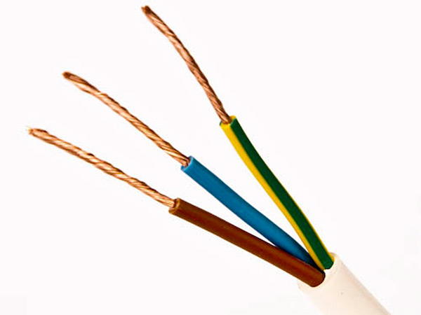
As in a two-wire network, one conductor is phase, the second is zero, but the third conductor is a protective earth wire that serves to protect against electric shock. In a three-wire network, a three-wire wire is used, usually with a brown, blue and yellow-green core.
The brown wire is a phase, the blue wire is the neutral conductor, the yellow-green wire is the conductor protective earth. To avoid confusion, it is not recommended to use a core with a yellow-green color as a phase or neutral conductor.
A three-core wire with colored wires is used to connect modern sockets European sample, which, in addition to the phase and zero contacts, also have a contact for connecting the ground conductor. Three-wire wires are also used to connect fixtures.
Color designations of wires in a three-phase network 380V
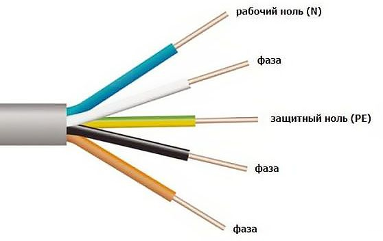
A three-phase electrical network can be four-wire or five-wire, i.e. with four or five wire cores. The only difference is the presence or absence protective conductor grounding. Those. a four-wire network is three phase conductors, a zero working conductor and the absence of a protective earth conductor. A five-wire network consists of three phase conductors, a zero working conductor and the presence of a ground conductor.
In both the four-wire and five-wire networks, a blue wire is used for the zero working conductor, and a yellow-green wire is used for the ground conductor. Concerning three phases A, B and C, then most often brown, black and gray cores are used for them, respectively. But there are also other colors of wire cores.
Four-core and five-core wire is used to connect three-phase load or for dividing a single-phase load into groups.
DC network
In a DC electrical network, two conductors are usually used. The first conductor is the plus and the second conductor is the minus. The red conductor is used as the positive conductor, and the blue conductor is used as the negative conductor.
As a result of all of the above, it is worth noting the following: despite certain standard requirements for the color marking of wires, it is not recommended to completely rely on the color of a particular wire core without preliminary verification.
In electrical installations and household electrical networks, conductors having various purpose. The main ones used for transmission electrical energy are the conductors phase voltage, zero working and zero protective.
All of them must be identified. Otherwise, even in the presence of fundamental, assembly or single line diagrams, explaining which contacts of electrical devices they are connected to, it will be impossible to figure it out. And the need for this arises constantly.
Another important reason requiring the identification of conductors is electrical safety. Touching any live parts, even those not under a life-threatening potential, is prohibited without checking the absence of voltage on them. But sections of the circuit containing both dangerous and safe potentials must be clearly marked. It is one of the many components of an organization. safe operation electrical installations.
Identification of conductors of power electrical circuits is carried out by two methods:
- conductors are painted in colors corresponding to their purpose;
- at the ends of the conductors or along their entire length, letter designations are applied that unambiguously determine the functional purpose.
Rules for applying color and letter marking to conductors used in power electrical circuits, are detailed in GOST R 50462-2009. Even though he has the status national standard RF, it completely repeats the IEC 60446-2007 standard. Thus, the rules for marking wires in Russia are brought into line with European standards. The relevance of this is dictated by the fact that Western equipment manufactured in accordance with European standards is supplied to Russia, and therefore, for its correct operation, our own rules must be brought into line with IEC.
So, now let's figure out what colors the wires and cable cores are for use in various circuits.
Marking of phase conductors
All Electricity of the net can be conditionally divided into:
- single-phase;
- three-phase;
- DC networks.
Each of them has its own rules for marking conductors. Let's start with phase.
In single-phase circuits, all phase conductors according to GOST must have Brown color. However, this does not mean at all that such wires should be used when installing a single-phase switchboard. Their color may not necessarily be brown, but any, but not blue or yellow-green. Additionally, the ends of the conductors can be marked with the letter L1, L2 or L3, indicating which phase of the three-phase network this shield is connected to.
However, if this single-phase circuit branches off from a three-phase one as part of a device or shield, then the color of its conductors must match the color of the wires of the phase to which it is connected: brown, black or gray.
Brown, blue and yellow-green colors are used for the cores of cables intended for the installation of single-phase networks.
Phase wires in three-phase networks used to be marked letters: A, B and C. In addition, tires were painted in the corresponding colors for identification:
- phase A - yellow;
- phase B - green;
- phase C - red.
Now GOST prohibits the use of green and yellow, as they can be confused with yellow-green, which has a different purpose, which will be discussed later.
It was not customary to mark the wires at all. A good example of this is the access switchboards. All the wires in them: both phase and zero are the same. An attempt to determine their purpose is fraught with some difficulties: after all, even to conclude that the conductor is connected to the phase of the mains, it is possible with certainty only when there is voltage on it, and you have an indicator in your hands. You can never be sure that the conductor is zero.
Therefore, GOST for phase conductors prescribes the following marking.
| phase wire | Letter | Color |
| Phase A (Phase 1) | L1 | brown |
| Phase B (phase 2) | L2 | black |
| Phase C (Phase 2) | L3 | grey |
It is allowed to mark wires in any of two ways or both at once. In the first case, tags with a letter designation are attached to the ends of the wires, in the second, the corresponding coloring of the current-carrying parts is used. Strictly speaking, use in switchboards when installing wires that have brown, black and gray colors not necessary at all. Color binding is more relevant to cable lines, as their veins are colored brown, black, gray, blue and yellow-green. When connecting cables to terminal blocks, consumers or to the outputs of electrical devices, it is necessary to comply with the requirements of GOST.
For the assembly of panel products, the installation of phase circuits is allowed to be carried out with single-color wires, while observing the conditions:
- blue color cannot be used;
- yellow-green color cannot be used;
- marking with letters applied to the beginning and end of the wire is required.
Western manufacturers do not paint tires in brown, black, gray, as well as blue and yellow-green, marking them with letter markings. At the same time, the cost of assembling panel products and complete switchgears decreases slightly. But instead, there is a drawback: in order to find out the purpose of the tire, you need to find the nearest marking plate on it or use the knowledge of the PUE, which indicates the requirements for relative position tires. But there are electrical installations in which the phase sequence cannot comply with the PUE. Therefore, when marking tires, it is necessary to stick the plates as often as possible. GOST prescribes marking at least twice within a panel or shield: at the bus inlet to the panel and at the output, or at its beginning and end.
Marking conductors "ground" and zero
Here, the labeling requirements are much more stringent, as this is directly related to electrical safety.
Protective zero (or ground), as well as live parts intended for the potential equalization system, are marked with alternating yellow and green stripes. For tires, this is a uniform alternation of yellow and green stripes, while wires and cable cores are colored appropriately at the factory.
It is prohibited to use yellow-green, as well as blue for marking other circuits, as well as marking the protective zero with other colors.
For the letter marking of the “ground” wire, the designation PE is provided, for the potential equalization conductor - GNYE.
Working zero is marked using only blue. Other markings, as well as the use of blue for other purposes, are prohibited. Working zero is denoted by the letter N.
It is a little more difficult to mark the zero combined, which is assigned the designation PEN. Since it combines the functions of a ground conductor and a working zero, this is also taken into account when marking. It is permissible to use two methods similar to each other: either take a wire that has a blue color and apply yellow-green markings at its ends, or apply blue markings at the ends of a yellow-green wire. This can be done either using insulating tape or heat shrink tubing.
Busbars for identification do not need to be painted over the entire length, since this method is difficult for these chains. On the tires designed to connect the conductors "ground" and zero, many holes are made for their connection, which makes solid coloring difficult, and at times impossible. It is allowed to apply colored stripes that have blue or yellow-green colors along the edges of the tire.
 (1 ratings, on average: 5,00 out of 5)

