Let's make a motion sensor together on our own. Assembling a motion sensor to turn on the light Schematic diagram of a sound motion sensor
Today, almost everyone knows what it is. This device has proven itself well, and office premises, and in the private sector. The cost is not always affordable. In this article we will describe in detail how to make a homemade sensor for lighting with your own hands, using a simple scheme.
Basic information about the motion sensor
Let's look at some information about the motion sensor for lighting and its scope.
A motion sensor is a device whose main function is to detect movement in its coverage area. There are three types of sensors - passive, active and mixed.
The operating principle of the active sensor is based on the radiation of ultrasonic and electromagnetic waves. Passive, has an infrared sensor that detects human heat. Mixed motion sensors have both control devices.
How the device works
Active sensors, by recording and comparing data received during radiation, alert movement if there is a shift in the data.
Advantages of ultrasonic sensors:
- Low cost.
- Unaffected by weather conditions.
- Recognize movement regardless of the material.
Disadvantages of ultrasonic devices:
- Range limitation
- They are designed for fairly sudden movements.
- Animals are sensitive to ultrafrequencies.
Most often, such devices are used in security systems for auto.
Pros of RF motion sensors:
- Their sizes are small.
- Long range models are available.
- Very accurate.
Disadvantages of radio frequency devices:
- Their cost is quite high.
- Due to the high sensitivity threshold, false motion detections occur.
- The high power of the device can have a bad effect on the human or animal body if left in the field for a long time.
They are used in security systems
Passive devices have infrared sensors that monitor the temperature within their range. When the temperature data changes, the device is triggered. This type of device is used more often for lighting in residential areas.
IR sensor device
Pros of an infrared sensor
- They are safe for people and animals.
- They can be easily customized.
- They work great both indoors and outdoors.
- The price is satisfactory.
Disadvantages of an infrared sensor
- Such a device only works within certain temperature limits.
- It does not pick up objects coated with infrared blocking material.
- The device malfunctions when exposed to heat flows from heaters and warm wind.
Everything you need for making
Required tools and elements for assembly:
- Volt-ohmmeter
- Soldering iron
- Wires
- Plumbing gasket
- Screw
- Laser pointer
- Transistors
- Photodiode FD 265
- Relay RES 55A
- Resistors
- power unit

Assembly diagram
Assembly works, work in stages
The motion sensor circuit for lighting is very simple. For those who have been involved in the repair of electrical appliances, this will not be difficult to do.
Stages of work:
- To get started, you should prepare the power supply. The connector should be cut off. Then use a voltmeter to find the plus.
- Then you should solder a 10 kohm resistor.
- The photodiode cathode must be soldered to a resistor, which is soldered to the positive.
- By soldering, we connect the photodiode anode to the construction resistor. The emitter of the transistor should be soldered to the negative of the resistor. The required collector is connected to the VT 1 base, which is soldered to R1.
- Then the emitter of VT 2 should be connected to the minus, the relay contact should be connected to the collector of VT 2. Another relay contact should be soldered to the plus of the power supply.
- The most common is the use of a laser pointer, and that’s what we use. To save money, we also solder two additional wires to the power supply.
- We insert the cord into the plumbing gasket, with the cap inside, you need to insert it into the pointer - so that the cap rests on the spring inside.
- One wire from the power supply should be connected to the screw, and the other should be inserted between the gasket and the body of the pointer.
Before turning on, you should check the diagram again. If everything agrees with the circuit, then we check the operation of the device.
How to connect the device and adjust the sensitivity
In order for the device to work properly and cope with the task, you need to take a responsible approach to its installation. The best place for installation is a doorway. For a more aesthetic appearance, the device can be placed in a plastic box by making a hole for the photodiode.
Mounts the sensor at a height of about a meter, from the floor. The pointer should be installed parallel to the floor and so that the beam hits the photodiode, then the sensitivity during operation of the device will not be impaired, and there will be no need to resort to repairing it.
After installation is complete, you can hide the wires so they won’t spoil appearance, and get underfoot. It is advisable to think about installing the device during repairs in the room, then it will be easier to hide the wires connecting to the lighting. When repairing, it is easier to think over the location of the device.
In order for the sensitivity to be good, you need to ensure that the pointer is set correctly. If it is installed correctly, then the sensitivity will be normal, and the device will not malfunction and will not need to be repaired.
When installing, it should be remembered that if the photodiode is dirty or the pointer beam is obstructed, it may disrupt the device's performance.
Summarize
Such a device is widely used when installing a security system using not only light, but also sound. This device lay down to connect to the lighting and make the light turn on automatically in the living room.
Thus, a system is created smart House. Enough economical option is such a device. It will help you significantly reduce your energy costs.

Various connection schemes
Very often it is used in bathrooms, in the kitchen, in hallways, and in the basements of a private house. In the bathroom and toilet, the device is connected not only to lighting, but also to ventilation, which greatly simplifies the ventilation of the room.
Several motion sensors with their own hands.
In this article we will start from the easiest and most primitive schemes and end with more complex and interesting solutions but first a little preface.
If you are reading this article in the hope of finding infrared motion sensor circuits or sensor circuits that are quite difficult to assemble at home, then this article is not for you. But if you decide to develop your horizons and your choice fell on studying the principles of operation of motion sensors, then this article is perfect for you.
The simplest motion sensor which you can come up with is a sensor using a wire resistor, or, as they are correctly called, potentiometric resistive converters. It’s worth making a small disclaimer that this is not exactly a motion sensor, but rather a displacement sensor and was included in the article only due to its simplicity.
Suppose we need to record the linear movement of a small-sized object from point A to point B. Here we need a similar sensor, since the use of more complex sensors for such purposes is simply impractical.
Picture 1:
As you can see, everything is very simple, our object is connected to a motor, which in turn moves across a resistor, changing the voltage on the voltmeter. It would not be entirely fair of me to keep silent about the fact that the design shown above is not entirely working. The problem is that the conversion of linear displacement into voltage does not occur according to a linear law, since usually these sensors are connected to some kind of load (in this circuit, instead of a voltmeter). But in the circuit shown in Figure 2, this drawback is eliminated.
Figure 2: 
Purpose of elements:
GB1- power supply.
R1- wirewound resistor.
R2– a resistor that shunts the upper arms of the potentiometer. For what? You will see this in Figure 3.
R3– load resistance, any type of indication can be connected here as a load, starting with ordinary light bulbs and ending with circuits capable of reproducing sound signal.
V– You can connect a voltmeter here.
Figure 3: 
The red line shows the motion-to-voltage conversion curve if there is no R2 in the circuit. And the green, almost straight line shows the transformation with R2.
Now let's discuss the advantages and disadvantages of such sensors.
+ Relatively simple to implement.
+ Fairly accurate.
Requires a little debugging before use. This debugging consists of taking a graph as in Figure 3 in order to determine the quality of the sensor.
Motion sensors using photocells.
Here, more difficult, but also interesting work lies ahead. We will take the simplest path, and to assemble such a sensor we will have to get a phototransistor. You can easily purchase it in a store or make it yourself, as it is not difficult enough. Take a transistor that has a package like in Figure 4.
Figure 4: 
Saw off upper part case so that a kind of window is formed at the top, or separate the case so that the entire crystal is exposed (Figure 5).
Figure 5: 
In this case, if light hits the transistor, it will work like a phototransistor, but perhaps in some cases will be less sensitive.
Now we need to assemble two fairly simple circuits. One circuit will be the light source and the other will be the photodetector circuit. Let's start from the end.
Figure 6: 
Purpose of elements:
VT1– phototransistor
R1– a resistor that performs two functions: it sets the operating point and plays the role of a collector load. Unfortunately, its denomination is selected empirically so please be patient.
C1- a capacitor, its purpose will be described in more detail below.
DA1 is an operational amplifier with feedback.
R2- a resistor on which the feedback of the op-amp is implemented. The higher its nominal value, the greater the gain, but it is worth remembering: the greater Ku, the less stability of the amplifier. Look for a middle ground.
The circuit works as follows. Light hitting VT1 can be mistaken for applying a small DC voltage to the base of the transistor. Then, after a beam of light hits VT1, it will open, capacitor C1 will charge, and at the moment when the light stops falling on the transistor, it will begin to discharge, while the voltage at point A will begin to gradually decrease. It follows that it will fall at the exit as well. Then why an operational amplifier? After all, you can do without it. Let's take it and make an output not after the op-amp, but from point A. This is possible, but the operational amplifier amplifies the signal taken at point A so that this sensor can be connected to various devices.
In fact, this is an ordinary photo sensor, you might think, and I would have to agree, but with only one caveat. Until we darken the transistor (the window sawn in the VT cover must be covered with dark light-transmitting material to reduce the influence of conventional lighting) and place a light source opposite it. Then we will have optical communication, and until someone blocks the light beam, the voltage at the output of the second part of the sensor will not change. But once the optical link is broken, the output voltage will almost instantly go to zero thanks to the op-amp.
Decide for yourself what to use as an emitter; you can install a simple LED, but then the distance to the photodetector will have to be greatly reduced. Or use a regular red laser, greatly gaining distance. Do you want the sensor to be invisible? Install IR diodes.
Also, do not forget that you can put a lens on the emitter that will focus the radiation.
I will not give diagrams of the emitter, since you just need to type the phrase “How to turn on an LED” into a search engine and you will get millions of diagrams.
We also need to analyze the information received from the sensor. To do this, we add one new element to the circuit - a relay.
Everything is very simple: we connect the relay winding to our input, apply voltage to one of the contacts, for me it is 12V. We ground the other, and on the third we connect, for example, a radio receiver, as in Figure 7.
Figure 7: 
Then, while light falls on the sensor, the power circuit of the receiver is connected to the case and the radio is silent, but when the light does not reach VT1, the relay is activated and closes the power circuit with 12V, Figure 8.
Figure 8: 
And then our radio will start working, thus giving you a sound signal. Instead of a radio, it can be whatever you want, it would be your imagination.
It is also important to clarify: if you decide to assemble this circuit and are not familiar with relays, familiarize yourself with the operating principle and basic parameters, this knowledge will greatly facilitate setting up the sensor.
Before finishing the article, a few words about the pros and cons.
+ Simple scheme.
+ Ability to analyze sensor states without converting the analog signal to digital.
- Complex calibration system.
A motion sensor is an electronic infrared device that detects the movement of living creatures and turns on power to lights and other electronic devices. Most often, such sensors are mounted for lighting, but can be used for other purposes, for example, turning on sound alarm.
The motion sensor operates on the principle of an electrical switch. We turn the usual one on and off mechanically by hand, and the motion sensor turns on automatically, reacting to movement, and turns off automatically when the movement stops.
The motion sensor is used in conjunction with lighting, as well as for turning on a sound alarm, opening doors, such as supermarket doors, etc.
Types of motion sensors
By location:
- Perimetric, used outdoors.
- Peripheral.
- Internal.
Based on the operating principle:
- Ultrasonic – a reaction to high-frequency sound waves.
- Microwaves – respond to high frequency radio waves.
- Infrared - uses heat radiation.
- Active - equipped with a receiver and transmitter.
- Passive - without a transmitter.
By type of operation:
- Thermal - work when the temperature changes.
- Sound - act on air vibrations.
- Oscillatory - triggered by the action of a magnetic field.
By design:
- 1-position - equipped with a transmitter and receiver in one housing.
- 2-position – receiver and transmitter in different housings.
- Multi-position - equipped with several blocks.
By type of installation:
- Multifunctional.
- Indoor.
- External.
- Overhead (wall-mounted).
- Ceiling (for suspended ceiling).
- Mortise (for offices).
Operating principle
The operating principle is not difficult to understand and is simple. The detector detects an object, sends a signal to the relay, which closes the circuit, the light turns on.
Connecting motion sensors using an example
To better understand how a motion sensor works, let’s conduct an experiment connecting it to a light bulb. For this we need:
- Motion Sensor.
- Electrical plug.
- Indicator screwdriver for phase search.
- Electric cartridge.
- Bulb.
- Screw clamp.
- The wire.
- Cleaning tool.
First, we will connect the light bulb directly to the socket, and then we will connect the motion sensor to the open circuit in order to understand the operation of the sensor.
Let's take it electrical wire and connect the ends to the plug. To strip the wire, we use a special stripping tool that is convenient to use. We install the cartridge on the opposite side. We turn on the light bulb.
By using indicator screwdriver We determine where the phase is in the socket. We insert the plug into the socket and make sure that the light is on. Now you need to install a motion sensor in the wire gap. Turn off the power supply and cut both wires. We clean the ends of the wires.
Now our task is to install the sensor into the gap in the supply wire. You need to connect a zero to the sensor according to the instructions to power it, and pass the phase through the sensor to the light bulb. The phase will go into the brown wire, come out of the red wire and go to the light bulb. We connect according to this diagram. Take the screw clamp and connect it.
There are two rheostats on the sensor itself. One rheostat is responsible for the time of day. It can be used not only for lighting, but also for turning on other devices. On the left knob, the sun is drawn to the left of it, and the moon is drawn to the right. That is, in order to use the sensor during daylight hours, we set the switch to the mode where the sun is indicated. If we use the sensor at night for lighting, then we switch the sensor to dark mode.

For our experience, we will turn on the checks in daylight mode, since we are doing the check in the light. The second sensor is responsible for the shutdown time. We can set it to minimum, and it will turn off after 5 seconds, or set it to maximum, that is, increase the time from the moment the movement stops. Now we turn on the plug in the socket, according to the previously established polarity. We make a movement with our hand, the sensor turns on the lamp. Now we don’t make any movements, a few seconds pass, the sensor turns off. Motion sensors are connected in a similar way.
Connection diagrams
The motion sensors are connected according to the usual circuit of closing and opening the light bulb circuit. If constant lighting is needed, but nothing moves, then a regular switch is included in the circuit parallel to the motion sensor. When the switch is turned on, the light will turn on due to the bypass circuit. When the switch is turned off, lighting control will transfer to the motion sensor.

Connecting motion sensors (several)
Most often, it happens that the shape of the room does not allow one sensor to cover its entire space, for example, around a bend in a corridor. In this case, several sensors are placed and connected in parallel. As a result of the activation of any sensor, the circuit is closed and voltage is supplied to the lighting devices. With this connection method, we must not forget that lighting lamps and sensors must be connected from the same phase. Otherwise a short circuit will occur.

Motion sensors are positioned in such a way that the viewing angle is greatest in the direction of the expected area of object movement. In this case, windows, doors and the interior of the room should not shield or interfere with the operation of the sensor.

Motion sensors have a permissible continuous power value of 500 to 1000 watts. Therefore, they are limited to high load use.

If it is necessary to turn on many powerful lighting devices, motion sensors are connected via .
When purchasing a sensor, see the installation and configuration instructions included with it. Usually the device diagram is indicated on the case. Under the sensor cover there is a connection block, and three contacts are visible by color. The wires are connected using clamps. If the cable is multi-core, then sleeve lugs are used.
Connection features
Electric current is supplied to the sensor through two conductors: brown - phase, and blue - zero. From the sensor, the phase goes to one contact of the light bulb. The other end of the lamp is connected to the zero terminal.
When movement occurs in the control location, the sensor is triggered and closes the relay contacts, which supplies a phase to the lamp.

The terminal block has screw terminals, so the wires are connected with lugs. It is recommended to connect the phase wire according to the diagram specified in the instructions.
Connecting motion sensors comes with some special features:
- After connecting the wiring, close the lid and proceed to connecting the wires in the junction box.
- 9 wires are supplied to the box: 2 - from the lamp, 3 - from the sensor, 2 - from the switch, 2 - zero and phase.
- Wires on the sensor: brown (white) - phase, blue (green) - zero, red - connection to the network.
- The wires are connected as follows: the phase wire (brown) is connected to the brown (white) phase wire of the sensor and the wire from the switch. The zero wire of the power cable is connected to the zero of the sensor and the zero of the lighting lamp.
- There are three wires left - red from the sensor, brown from the lamp and the second wire from the switch. They are connected.
The sensor is connected to the lighting. After power is applied, the sensor shows its reaction to movement, thereby closing the lighting circuit.
Installation instructions
We figured out the connection diagram and operating principle. Now there remains an important and final stage of work - to deal with the installation of the motion sensor.

To independently install and connect motion sensors to the power supply, you must follow a certain procedure:
- Select the connection diagram (one sensor or several, with or without a switch, etc.).
- Determine the most suitable place and direction for mounting the motion sensor. Usually the sensor is fixed on the ceiling or in the corner of the room. When installing outdoors, you need to look at the situation. The main parameter is the viewing angle of the sensor. It is necessary to select the most suitable location for the sensor housing so that there are no dead zones (places that the sensor does not cover with its action). To do this, it is recommended to use lamp supports or load-bearing wall building.
- Turn off the electricity at the switchboard to ensure safety when connecting wires.
- According to the selected circuit option, connect three wires to the contacts of the sensor housing and in the housing of the lighting device. At the same time, do not forget about observing the markings according to the colors of the wires and the designations of the connectors, in order to avoid confusion. If you connect the zero and phase incorrectly, you expose yourself to danger and also damage the electrical wiring, so when connecting you need to work carefully and carefully.
- On the sensor body, you need to adjust the regulators, select their optimal settings. There can be several common controls on the sensor body: Lux - light level for triggering, Time - time delay for turning off the light, Sens - sensor sensor sensitivity, Mic - noise level for sensor triggering. These settings are individual in each case.

- Apply power to the distribution board and test the operation of the motion sensor. If necessary, change the location of the sensor, or reconfigure the sensitivity and other settings.
When connecting the sensor to garden plot, it is better to place it further from bushes, trees and other objects that create interference.
Motion sensors - incredible convenient thing, which allows you to control the light in the room or control the opening and closing of doors, and can also notify you of unwanted guests. In this article we will tell you how to make a motion sensor with your own hands at home and consider the scope of possible applications of these devices.
Briefly about sensors
One of the simplest types of sensors is a limit switch or self-resetting button (without fixation).
It is installed near the door and reacts to its opening and closing. Using a simple circuit, this device turns on the light in the refrigerator. It can be equipped with a storage room or hallway vestibule, a door at the entrance, emergency LED lighting, or use this switch as an alarm that will notify you about the opening or closing of the door. Disadvantages of the design may be difficulties in installation, and sometimes unpresentable appearance.
 Devices based on magnets can be seen on the doors and windows of protected objects. Their operating principle is very similar to that of a button. A reed switch can open or connect contacts when a conventional magnet is brought to it. Thus, the reed switch itself is installed on the doorway, and the magnet is hung on the door. This design looks neat and is used more often than a regular button. Lack of devices for highly specialized applications. They are not suitable for monitoring open areas, squares, and passages.
For open passages, there are devices that respond to changes in the environment. These include photo relays, capacitive (field sensors), thermal (PIR), sound relays. To record the intersection of a certain area, control an obstacle, or the presence of movement of an object in the overlap area, photo or sound echo devices are used.
The operating principle of such sensors is based on the formation of a pulse and its recording after reflection from an object. When an object enters such a zone, the characteristic of the reflected signal changes, and the detector generates a control signal at the output.
For clarity, a schematic diagram of the operation of a photo relay and sound relay is presented:

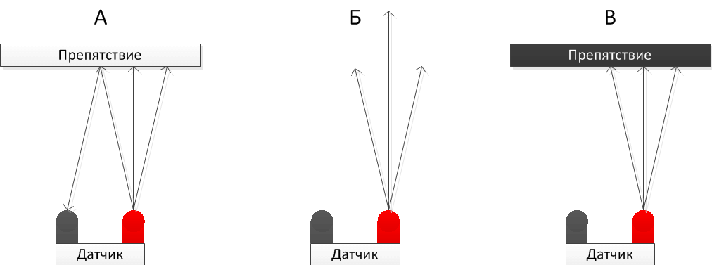
As a transmitting device in optical sensors Infrared LEDs are used, and phototransistors are used as a receiver. Sound sensors operate in the ultrasonic range, so their operation appears silent to our ears, but each of them contains a small emitter and a detector.
For example, it is great to equip a backlit mirror with a motion detector. The lighting will turn on only at the moment when a person is directly next to it. Don't want to make one yourself?
Assembly diagrams
Microwave
To control open spaces and control the presence of objects in the desired zone, there is a capacitive relay. The operating principle of this device is to measure the amount of radio wave absorption. Everyone has observed or been a participant in this effect when, approaching a working radio receiver, the frequency on which it operates gets lost and interference appears.
Let's talk about how to make a microwave-type motion sensor. The heart of this detector is a radio microwave generator and a special antenna.  This circuit diagram shows a simple way to do microwave sensor movements. Transistor VT1 is a high-frequency generator and also a radio receiver. The detector diode rectifies the voltage by applying a bias to the base of transistor VT2. The windings of transformer T1 are tuned to different frequencies. In the initial state, when the antenna is not affected by external capacitance, the amplitudes of the signals are mutually compensated and there is no voltage on the detector VD1. When the frequency changes, their amplitudes are added and detected by a diode. Transistor VT2 begins to open. As a comparator for clear processing of the “on” and “off” states, thyristor VS1 is used, which controls a 12-volt power relay.
Below is an effective diagram of a presence relay using available components, which will help you assemble a motion detector with your own hands or simply be useful for getting acquainted with the device.

Thermal
Thermal IR (PIR) is the most common sensor device in the business sector. This is due to cheap components, simple assembly scheme, lack of additional complex settings, wide temperature range work.

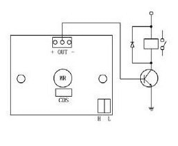
The finished device can be purchased at any electrical goods store. Often this sensor is supplied with lamps, alarm devices and other controllers. However, now we will tell you how to make a thermal motion sensor at home. A simple pattern to follow looks like this:  A special thermal sensor B1 and a photo element VD1 make up an automated lighting control complex. The device starts working only after dusk; the response threshold can be set with resistor R2. The sensor connects the load when a moving person enters the control zone. The time of the built-in timer for shutdown can be set using the R5 regulator.
Homemade module for Arduino
An inexpensive sensor can be made from special ready-made boards for a radio designer. This way you can get a fairly miniature device. For assembly we will need a motion sensor module for Arduino microcontrollers and a single-channel relay module.

Each board has a three-pin connector, VCC +5 volts, GND -5 volts, OUT output on the detector and IN input on the relay board. In order to make a device with your own hands, you need to supply 5 Volts (plus and minus) to the boards from the power source, for example, from a phone charger, and connect out and in together. Connections can be made using connectors, but it will be safer to solder everything. You can follow the diagram below. A miniature transistor, as a rule, is already built into the relay module, so there is no need to install it additionally.
 When a person moves, the module sends a signal to the relay and it opens. Note that there are high and low level relays. It must be selected based on the signal the sensor produces at the output. The finished detector can be placed in a housing and masked in in the right place. Additionally, we recommend watching videos that clearly demonstrate assembly instructions homemade sensors movements at home. If you still have any questions, you can always ask them in the comments.
Like(0) Dislike( 0 )
. Motion sensor circuits
LX01, electrical circuit diagram, connection, installation rules
On given time The most common and popular motion detection device is the volumetric passive infrared motion detector.
The principle of its operation is based on the reception of thermal radiation from any object by a pyroelectric infrared receiver. This element works in conjunction with a field-effect transistor, which acts as a pre-amplifier.
In order for the range of thermal waves emitted by the human body (5 - 14 microns) to be perceived by the photodetector, special light filters are used
To minimize false positives The design of the sensor includes two such receivers connected in a counter circuit.
Depending on external illumination and temperature, voltages are generated by each sensor separately. Their signals are subtracted and compensated, and when the threshold value is exceeded, the device reacts to movement.
Motion sensor LX01
 Let's take the LX01 detector as an example. The device consists of two boxes: mounting and hardware, which are connected by a movable bracket that facilitates setting the scanning area.
The hardware box contains a control board to which sensors are attached: a pyroelectric one that recognizes movement, a photosensitive photoresistor for determining the level of illumination.
The sensors are covered by a translucent plastic curtain with Fresnel lens elements pressed out over the entire area.
At the end there are corrugated handles for operational regulators connected to trimming resistors.
The mounting box has holes for exiting wires and fastening the housing of the lighting device.
The device is designed for switching electrical circuits with total load up to 1200 W. The device can be connected to incandescent lamps and other lighting elements designed for an alternating current voltage of 200 - 230 V.
Unlike detectors used exclusively for systems alarm system the device has Extra options regulating operation.
“TIME” regulator – adjusts the time after which the device turns off the lighting; if a person continues to be in the range of the device, the light will be turned on again.
Unlike presence detectors, motion sensors, when switched again, completely turn the lighting device on and off at a fast pace, which, if the response period is incorrectly set, leads to flickering of the light.
“DAYLIGHT” regulator – sets the light sensitivity of the device and allows you to accurately determine the eclipse threshold for automatically turning on the lighting.
“SENS” regulator – sets the sensitivity of the pyroelectric sensor of the detection detector. It can be used to adjust the radius of the detection zone.
Technical parameters of motion sensor LX01
- Scanning zone angle 1200.
- Maximum detection range 12m.
- Power supply: alternating current from 180 to 240V at 20mA.
- Shutdown time 5sec-600sec.
- Photosensitivity in the range of 10-2000 Lux.
The device is sensitive to low temperatures environment and maintains performance only up to -100C. It is recommended to install indoors at a height of 2m to 4m.
Schematic diagram of a motion sensor
The LX01 model includes an infrared sensor that detects movement and elements that amplify and process the signal.
A passive, infrared pyroelectric sensor is a transparent quartz plate that transmits infrared rays and a ceramic sensor.
There is also an amplifier in the housing that matches the high output voltage coming from the sensor.
The RE-46 pyroelectric sensor, which is used in the LX01 motion detector, is connected to an LM324N operational amplifier. He has complex structure, consisting of four stages of amplifiers.
The functions of amplifiers DA1.1 and DA1.2 are to correct the incoming signal with subsequent transmission to the third stage - DA1.3.
The comparator, which is connected to it, recognizes the preprocessed signal. The fourth stage DA1.4 regulates the lighting time.
It should be noted that with this principle of processing incoming signals, determining a moving object is reduced not to registering the presence of thermal radiation, but to identifying the dynamic changes in such radiation.
The photoresistor (R23), which determines the level of external lighting, is controlled by the tuning resistor R24, which in turn is connected to the base contact of the VT1 transistor.
If the light intensity increases, then the resistance of the photoresistor drops, and accordingly the current at the base of the transistor increases. It opens and the effect of raising the contact potential between resistors R25 / 21 and the ground potential occurs.
Thus, the signal from the DD1.4 cascade is prohibited from entering the base terminal of transistor VT2, which activates the connecting relay K1. If the relay is triggered earlier, the operation of the photoresistor will be blocked by diode VD4 for the entire period of the active phase.
The device operates from a regular power supply 220V, 50Hz. Voltage is supplied to the device through the fuse FU. Through the input of the quenching capacitor (C11 in the diagram) and the diode bridge (VD7-10), the output voltage will be 18 - 22 volts.
Next, the voltage is smoothed and rectified by capacitor C12 and supplied to the DA2 78L08 stabilizer. The increased voltage that appears at the output of the stabilizer is sent to the zener diode (in the VD6 diagram), which dampens it to 24V. When switching relay contacts, switching noise occurs, which is suppressed by a sequence of resistor R26 and C10.
Connection diagrams
 This model is designed for direct connection of lighting devices powered from the mains with alternating current 220V, but the power of connected devices is limited to no more than 1 kW.
For additional control lighting, which provides for both automatic and manual activation of the lighting device, the following diagram is used for connecting a motion sensor through a junction box.
It is possible to connect several motion detectors to control one lighting fixture. Such circuits are used to refresh staircases or long corridors that cannot be fully monitored by a single detector.
In order to increase the maximum load, use the method of connecting a motion sensor through an intermediate relay.

In this case, the maximum power consumption will be limited only by the load capacity parameters of the intermediate relay used. Thus, it is possible to connect powerful halogen spotlights with a load of several kilowatts.
Using as lighting elements, mercury lamps daylight, it should be remembered that the period between switching on must correspond to the cooling time of the lamp.
Rules for installing a motion sensor
 The stability and efficiency of the alarm system is influenced by the location chosen to install the motion detector.
In this case, it is necessary to choose correctly not only general scheme, but also a connection point in each room. When determining it, it is necessary to minimize Negative influence external factors, which can lead to false alarm system activation.
Avoid exposure to convection and intense air flows (air conditioners and radiators), as well as direct sun rays.
In addition, the surface on which the sensor is installed should not be subject to vibration or vibration (from opening a door or window).
The traditional installation of the detector is in a shaded corner of the room at a height of no more than 2.4-3 m with the scanning area directed towards the center of the room.  Symbols on the diagram: 1. Motion sensor2. Glass break sensor3. Reed switch4. Smoke detector
nabludau.ru
Motion sensor diagrams: types, device, connection and principle of operation
 Motion sensors are one of the main elements of security alarm systems. They record the slightest movements of a physical object that is in the control zone of such a sensor, and when triggered, they activate an alarm signal. By design, such a sensor is a relay that reacts to movement, and therefore such devices are widely used in automatic light control systems. There are motion sensors whose operation is based on different physical principles, so the design of the motion sensor may differ. All devices of this type are very compact, differ good design and fit into the interior of any room.
- Typical motion sensor circuit
- Wiring diagram for a motion sensor for lighting
- Scheme for connecting a motion sensor for an alarm
Design, types and features of motion sensors
Exist and are widely used following types motion sensors:
- Radio waves;
- ultrasonic;
- infrared;
- Hybrid.
Radio wave or microwave sensors operate on the Doppler effect. The main elements of such a sensor are a microwave signal emitter and a reflected signal receiver. If any object moves in the radiation field, the frequency of the reflected signal changes. An electronic circuit processes the difference between the direct and reflected signal and switches a relay, which can turn on a siren or sound an alarm. Radio wave motion sensors are highly sensitive, but are quite expensive. In children's and medical institutions microwave sensors are not used due to microwave radiation, despite the fact that its level is minimal and absolutely harmless. Due to their high sensitivity, radio wave sensors are susceptible to false alarms.
Ultrasonic sensors also use the Doppler effect, but instead of high-frequency oscillations, such systems use ultrasound. These devices have found application in Parktronic parking systems, but are rarely used in everyday life. The frequency of 25-60 KHz is well heard by cats and dogs, so the use of such sensors causes them severe stress. In addition, ultrasonic sensors have a short range and can be fooled by moving slowly.
In security alarms and automatic lighting control systems, infrared volumetric motion sensors are most often used. The thermal (infrared) radiation of an object that passes in the sensor’s capture zone hits the IR sensor through the Fresnel lens, after which an alarm signal is generated at the output of the electronic circuit (the circuit breaks).

IR motion sensor device
Due to their low cost, such devices are widely used for automatic lighting control, for example, in an entrance, when when a person appears, the lighting turns on for 1-3 minutes and then turns off. To control the lights in a parking lot or local area street motion sensors are used.
Hybrid or combined motion sensors are two sensors different designs, placed in one housing and connected to various inputs of the security alarm device. Typically, infrared and radio wave motion sensors are combined in one housing. The use of such devices increases the reliability of the security system. They can be used in banks, depositories and money vaults. The circuit for switching on a motion sensor for an alarm allows you to generate an alarm signal and control the operation of a siren or spotlight. Motion sensors may have the following main characteristics:
- Sensitivity;
- The presence of an anti-sabotage zone;
- The volume of the capture zone horizontally and vertically;
- Supply voltage.
Motion sensors with constant sensitivity are not recommended for use in apartments where there are pets, otherwise, in the absence of the owners, an alarm will sound for each passage of the cat. The magnitude of the response threshold can be adjusted, depending on the design, smoothly or with special jumpers on the board. There are also models of sensors that do not react to animals.
The anti-sabotage zone is additional zone grip directed vertically downwards from the sensor and blocking an attempt to disable the device. The passport indicates the viewing angle of the sensor in degrees and the dimensions of the guaranteed response zone. All sensors, regardless of design, are connected to typical devices, therefore the connection diagram of the motion sensor is always the same, and their supply voltage is usually 12V. An LED is usually installed on the case, indicating the standby or operation mode.
Typical motion detector circuit
All models of volumetric infrared motion sensors are similar in circuitry and design. There may be differences in some electrical parameters and housing design. The motion sensor circuit consists of the following elements:
- PIR sensor;
- Operational amplifier;
- Thermal compensation circuit;
- Comparator;
- Relay.
Passive Infrared Sensor records the temperature of a foreign object caught in the capture zone. The signal is amplified by an operational amplifier and sent to a comparator, which compares the signal corresponding to the ambient temperature and the signal received from the PIR sensor. The difference in signal levels indicates the presence of a thermal background of a foreign object. The difference potential causes the relay to operate, the contacts of which can be used to switch on various devices.

Operating principle of an infrared motion sensor
If the room temperature approaches the temperature of the human body, which could interfere with the operation of the device, the temperature compensation system is activated. The popular model of infrared motion sensor Colt 10 DP has the following main characteristics:
- Object detection zone – 10 meters 90°;
- Does not react to animals up to 10 kg;
- 3 sensitivity settings;
- Digital thermal compensation circuit;
- Not susceptible to electromagnetic radiation up to 50 V/m;
- Has protection against static electricity;
- Supply voltage – 9-16 V;
- Operating temperature range -25… + 60°С.
The sensor circuit contains a solid-state relay, which can be used to control external devices.
The figure below shows a typical motion sensor circuit using the LX-02 as an example.

Diagram of a typical motion detector using the example of LX02
Connecting a motion sensor for lighting
The low cost and reliability of infrared motion sensors allows them to be used to automatically turn on lighting. The motion sensor circuit for lighting consists of the same elements as a traditional security sensor. It is based on an element sensitive to infrared radiation. An electronic circuit processes the signal and controls the light source through a relay. Such systems are widely used in the entrances of multi-storey buildings, when the lighting is turned on only when a person appears in the room. After a certain time, the light turns off automatically. The connection diagram for a motion sensor for lighting is very simple and can be done independently.

Connecting an IR motion sensor used to turn on the light
Under the back cover of the motion sensor there is a block with three terminals, which are labeled with the letters “L”, “N” and “A”. Terminal “L” is connected to the phase wire of the network, which must be determined using an indicator screwdriver. A neutral wire is supplied to the “N” terminal, and the light source is connected between the “N” and “A” terminals, that is, the motion sensor relay controls the phase, and zero is supplied constantly. Motion sensors for turning on lights can also be used as an element of security for a country house, when when an intruder enters, the spotlight and siren turn on.

Connecting a sensor with a switch
In order for the lighting source to be controlled either automatically or manually, a switch is added to the circuit. Connecting a motion sensor via a switch is very simple. The mains voltage of 220 volts is also supplied to the “L” and “N” terminals, and a regular two-position switch is placed between the “L” and “A” terminals.
Sensor connection diagram for alarm
Almost all models of motion sensors, regardless of the operating principle, are connected to the security alarm control panel (RCD) via standard scheme. To gain access to the connection panel, you must remove decorative cover. Under it there is an electronics board and a block of three double terminals:
- Power supply - +12 V and “General”;
- Relay – N,C;
- Tamper – T,T.

Connecting an IR motion sensor with an alarm system
Supply voltage is supplied to the power terminals from the power supply unit or the GSM alarm device. The relay terminals are not polarized and are closed in standby mode. When a physical object appears in the detection zone, its thermal radiation is received by the PIR sensor, which causes the relay to operate and the circuit opens. This entails turning on the alarm signal of the control panel. On the device itself, you can select a self-healing mode, when the termination of the radiation source puts the motion sensor into standby mode and the alarm is turned off automatically.
In another mode, the alarm signal is given continuously until the "Reset" button on the base unit of the security system is pressed. The scheme for connecting a motion sensor to an alarm system implies protecting the device from unauthorized opening of the case. To do this, the design of the sensor provides a microswitch, the contacts of which are brought to the "Tamper" terminals.
In order to avoid false positives of the motion sensor, you must follow some rules. According to the technology, such sensors are usually installed on the walls or in the corners of rooms at a height of at least 2 meters. The sensor is mounted using a special bracket that allows you to choose the orientation of the sensor horizontally and vertically. The sensor must not be pointed at windows, sources artificial lighting and devices that generate strong electromagnetic radiation. In everyday life, such devices include, first of all, microwave ovens.
With this they read:
Did you like the article? Share with friends on social networks!nabludaykin.ru
Connection of motion sensors. Scheme. Types and operation
A motion sensor is an electronic infrared device that detects the movement of living things and turns on power for lights and other electronic devices. Most often, such sensors are installed for lighting, but can be used for other purposes, for example, turning on a sound alarm.
The motion sensor operates on the principle of an electrical switch. Ordinary electric switch we turn it on and off mechanically by hand, and the motion sensor turns on automatically in response to movement, and turns off automatically when the movement stops.
The motion sensor is used in conjunction with lighting, as well as for turning on a sound alarm, opening doors, such as supermarket doors, etc.
Types of motion sensors
By location:
- Perimetric, used outdoors.
- Peripheral.
- Internal.
Based on the operating principle:
- Ultrasonic – a reaction to high-frequency sound waves.
- Microwaves – respond to high frequency radio waves.
- Infrared - uses heat radiation.
- Active - equipped with a receiver and transmitter.
- Passive - without a transmitter.
By type of operation:
- Thermal - work when the temperature changes.
- Sound - act on air vibrations.
- Oscillatory - triggered by the action of a magnetic field.
By design:
- 1-position - equipped with a transmitter and receiver in one housing.
- 2-position – receiver and transmitter in different housings.
- Multi-position - equipped with several blocks.
By type of installation:
- Multifunctional.
- Indoor.
- External.
- Overhead (wall-mounted).
- Ceiling (for suspended ceiling).
- Mortise (for offices).
Operating principle
The operating principle is not difficult to understand and is simple. The detector detects an object, sends a signal to the relay, which closes the circuit, the light turns on.
Connecting motion sensors using an example
To better understand how a motion sensor works, let’s conduct an experiment connecting it to a light bulb. For this we need:
- Motion Sensor.
- Electrical plug.
- Indicator screwdriver for phase search.
- Electric cartridge.
- Bulb.
- Screw clamp.
- The wire.
- Cleaning tool.
First, we will connect the light bulb directly to the socket, and then we will connect the motion sensor to the open circuit in order to understand the operation of the sensor.
We take an electrical wire and connect the ends to the plug. To strip the wire, we use a special stripping tool that is convenient to use. We install the cartridge on the opposite side. We turn on the light bulb.
Using an indicator screwdriver, we determine where the phase is in the outlet. We insert the plug into the socket and make sure that the light is on. Now you need to install a motion sensor in the wire gap. Turn off the power supply and cut both wires. We clean the ends of the wires.
Now our task is to install the sensor into the gap in the supply wire. You need to connect a zero to the sensor according to the instructions to power it, and pass the phase through the sensor to the light bulb. The phase will go into the brown wire, come out of the red wire and go to the light bulb. We connect according to this diagram. Take the screw clamp and connect it.
There are two rheostats on the sensor itself. One rheostat is responsible for the time of day. It can be used not only for lighting, but also for turning on other devices. On the left knob, the sun is drawn to the left of it, and the moon is drawn to the right. That is, in order to use the sensor during daylight hours, we set the switch to the mode where the sun is indicated. If we use the sensor at night for lighting, then we switch the sensor to dark mode.
For our experience, we will turn on the checks in daylight mode, since we are doing the check in the light. The second sensor is responsible for the shutdown time. We can set it to minimum, and it will turn off after 5 seconds, or set it to maximum, that is, increase the time from the moment the movement stops. Now we turn on the plug in the socket, according to the previously established polarity. We make a movement with our hand, the sensor turns on the lamp. Now we don’t make any movements, a few seconds pass, the sensor turns off. Motion sensors are connected in a similar way.
Connection diagrams
The motion sensors are connected according to the usual circuit of closing and opening the light bulb circuit. If constant lighting is needed, but nothing moves, then a regular switch is included in the circuit parallel to the motion sensor. When the switch is turned on, the light will turn on due to the bypass circuit. When the switch is turned off, lighting control will transfer to the motion sensor.
Connecting motion sensors (several)
Most often, it happens that the shape of the room does not allow one sensor to cover its entire space, for example, around a bend in a corridor. In this case, several sensors are placed and connected in parallel. As a result of the activation of any sensor, the circuit is closed and voltage is supplied to the lighting devices. With this connection method, we must not forget that lighting lamps and sensors must be connected from the same phase. Otherwise a short circuit will occur.
Motion sensors are positioned in such a way that the viewing angle is greatest in the direction of the expected area of object movement. In this case, windows, doors and the interior of the room should not shield or interfere with the operation of the sensor.
Motion sensors have a permissible continuous power value of 500 to 1000 watts. Therefore, they are limited to high load use.
If it is necessary to turn on many powerful lighting devices, the motion sensors are connected through a magnetic starter.
When purchasing a sensor, see the installation and configuration instructions included with it. Usually the device diagram is indicated on the case. Under the sensor cover there is a connection block, and three contacts are visible by color. The wires are connected using clamps. If the cable is multi-core, then sleeve lugs are used.
Connection features
Electric current is supplied to the sensor through two conductors: brown - phase, and blue - zero. From the sensor, the phase goes to one contact of the light bulb. The other end of the lamp is connected to the zero terminal.
When movement occurs in the control location, the sensor is triggered and closes the relay contacts, which supplies a phase to the lamp.
The terminal block has screw terminals, so the wires are connected with lugs. It is recommended to connect the phase wire according to the diagram specified in the instructions.
Connecting motion sensors comes with some special features:
- After connecting the wiring, close the lid and proceed to connecting the wires in the junction box.
- 9 wires are supplied to the box: 2 - from the lamp, 3 - from the sensor, 2 - from the switch, 2 - zero and phase.
- Wires on the sensor: brown (white) - phase, blue (green) - zero, red - connection to the network.
- The wires are connected as follows: the phase wire (brown) is connected to the brown (white) phase wire of the sensor and the wire from the switch. The zero wire of the power cable is connected to the zero of the sensor and the zero of the lighting lamp.
- There are three wires left - red from the sensor, brown from the lamp and the second wire from the switch. They are connected.
The sensor is connected to the lighting. After power is applied, the sensor shows its reaction to movement, thereby closing the lighting circuit.
Installation instructions
We figured out the connection diagram and operating principle. Now there remains an important and final stage of work - to deal with the installation of the motion sensor.
To independently install and connect sensors to the power supply, you must follow a certain procedure:
Select the connection diagram (one sensor or several, with or without a switch, etc.). Determine the most suitable place and direction for mounting the motion sensor. Usually the sensor is fixed on the ceiling or in the corner of the room. When installing outdoors, you need to look at the situation. The main parameter is the viewing angle of the sensor. It is necessary to select the most suitable location for the sensor housing so that there are no dead zones (places that the sensor does not cover with its action). To do this, it is recommended to use lantern supports or a load-bearing wall of the building.
Turn off the electricity at the switchboard to ensure safety when connecting wires.
According to the selected circuit option, connect three wires to the contacts of the sensor housing and in the housing of the lighting device. At the same time, do not forget about observing the markings according to the colors of the wires and the designations of the connectors, in order to avoid confusion. If you connect the zero and phase incorrectly, you expose yourself to danger and also damage the electrical wiring, so when connecting you need to work carefully and carefully. On the sensor body, you need to adjust the regulators, select their optimal settings. There can be several common controls on the sensor body: Lux - light level for triggering, Time - time delay for turning off the light, Sens - sensor sensor sensitivity, Mic - noise level for sensor triggering. These settings are individual in each case.
Apply power to the distribution board and test the operation of the motion sensor. If necessary, change the location of the sensor, or reconfigure the sensitivity and other settings.
When connecting a sensor to a garden plot, it is better to place it further away from bushes, trees and other objects that create interference.
Related topics:
electrosam.ru
DIY motion sensor at home: video, diagram, photo
The presence of various detectors in the room allows you to monitor and manage most modern houses, remotely and automatically, according to a predetermined algorithm, without constant human control. In this article we will discuss how to make a motion sensor with your own hands at home, and also consider the scope of possible applications of these devices.
Briefly about sensors

A limit switch or self-resetting button installed at the door and responsive to opening and closing is the simplest motion sensor (intrusion, opening). Using a simple circuit, this device turns on the light in the refrigerator. You can also equip a storage room or vestibule in the hallway, a door in the entrance, with emergency LED lighting using this switch or an alarm that will notify you when it is triggered.  Such devices, based on a reed switch and a magnet, can be seen on the doors and windows of protected objects. Lack of devices for highly specialized applications. They are not suitable for monitoring open areas, squares, and passages.
For open passages, there are devices that respond to changes in the environment. These include photo relays, capacitive (field sensors), thermal (PIR), sound relays. To record the intersection of a certain area, control an obstacle, or the presence of movement of an object in the overlap area, photo or sound echo devices are used.
The operating principle of such devices is based on the formation of a pulse and its recording after reflection from an object. When entering such a control zone, the characteristic of the reflected signal changes, and the detector generates a control signal at the output.
For clarity, a schematic diagram of the operation of a photo relay and sound relay is presented:


Interactive slot machines, automatic doors, voice detectors, security alarm and other automation that responds to the precise position of an obstacle or object.
For example, it is great to equip a backlit mirror with a motion detector. The lighting will turn on only at the moment when a person is directly next to it. Would you like to make this kind of mirror lighting yourself?
Assembly diagrams
Microwave
To control open spaces and monitor the presence of objects in the controlled area, a capacitive relay has been developed. The operating principle of this device is to measure the amount of radio wave absorption. Everyone has probably observed or been a participant in this effect, when approaching a working radio receiver, it begins to change the wavelength or make noise, losing the station. Let's talk about how to make a microwave-type motion sensor. The heart of this detector is a radio microwave generator and a special antenna.  This circuit diagram shows a simple way to make a microwave motion sensor. Transistor VT1 is a high-frequency generator and also a radio receiver. The detector diode rectifies the voltage by applying a bias to the base of transistor VT2. The windings of transformer T1 are tuned to different frequencies. In the initial state, when the antenna is not affected by external capacitance, the signal amplitudes are mutually compensated and there is no voltage on the VD1 detector. When the frequency changes, their amplitudes are added and detected by a diode. Transistor VT2 begins to open. As a comparator, for a clear working out of the on and off state, a thyristor VS1 is used, which controls a 12 volt power relay.
Below is a working diagram of the presence relay on the available components, which will help you assemble a motion detector with your own hands or just come in handy to get acquainted with the device.

Thermal
Thermal IR (PIR) is the most common sensor device in the business sector. This is due to cheap components, a simple assembly scheme, the absence of additional complex settings, and a wide temperature range of operation.

The finished device can be purchased at any electrical goods store. Often this sensor is supplied with lamps, alarm devices and other controllers. However, now we will tell you how to make a thermal motion sensor at home. A simple pattern to follow looks like this:
 A special thermal sensor B1 and a photo element VD1 make up an automated lighting control complex. The device starts working only after dusk, set by the level of the resistor R2, when a moving person enters the control zone. The time of the built-in timer can be set with regulator R5.
Homemade on Arduino
An inexpensive sensor can be made from special boards for a radio designer. A fairly miniature device is assembled from ready-made modules. For assembly we will need a motion sensor module for Arduino microcontrollers and a single-channel relay module.

Each board has a three-pin connector, VCC +5 volts, GND -5 volts, OUT output on the detector and IN input on the relay board. In order to make a working device with your own hands, you need to supply 5 volts to the boards from the power source, and connect out and in together. The result should look like this in the diagram below.  The finished detector can be placed in a housing or disguised in convenient location. Finally, we recommend watching a video that clearly demonstrates instructions for assembling homemade motion sensors at home:
Now you know how to make a motion sensor with your own hands. We hope the provided diagrams and videos helped you in assembling a homemade sensor!
samelectrik.ru
Wiring diagram for a motion sensor for lighting

A motion sensor is an electronic infrared device that allows you to detect the presence and movement of a person and helps switch power to lighting devices and other devices. electrical appliances. It is based on a special detector of temperature changes in space (read about the PIR sensor here). Nowadays there are a lot of models of various Chinese detectors on sale, which are almost all similar to each other and differ only in the design and power of the switched lamps - the connection diagram itself is usually the same.
If you need to connect several powerful lamps at once through this device, then the best solution will apply magnetic starter or a powerful relay.
Installation Features
To install it, you need to choose a place that provides the best viewing angles both horizontally and vertically with a maximum coverage area. Most PIR motion sensors have a dead zone, the location of which should be taken into account when choosing their placement height and angle of inclination.
 Motion sensor HC-SR501 with regulators
 If the sensor is made in a fixed housing and does not have positioning adjustment, then it is necessary to check the technical data sheet for correct placement of the device. Sometimes this device requires the presence of not only phase and neutral wires, but also ground (ground). Although most operate from a regular two-wire 220 V network.
Electrical connection diagrams
How to connect a motion sensor with a switch

An option in which it is installed parallel to a conventional switch.
How to connect a motion sensor without a switch

And this is for connecting it directly to a 220 V network without any other buttons.
How to connect several sensors to the network at once

On long stairs or corridors you may need several pieces controlling one lamp or long led strip white glow.

Inside the PIR sensor there is usually terminal block, which displays standardly colored and labeled contacts:
- L, brown or black - phase wire.
- N, blue - neutral wire.
- Ls or L’, red - phase return to lighting lamps.
- ⊥, yellow-green - protective earth.
Lighting devices should be connected between contacts A and N. Electrical power should be supplied to L and N, strictly observing the polarity of the connection phase. If you are interested in the circuit diagram of the detector, then follow the link at the beginning of the article.
Setting and adjusting the sensor
After installation, it is necessary to carry out the procedure for adjusting the motion sensor for lighting. After all, the geometry of the room is different for everyone (humidity, lighting, wall material).
- LIGHT or LUX - illumination sensitivity threshold.
- TIME - trigger timer.
- SENSE - sensitivity.
The usual limits for adjusting the timer response time are set in most devices from a few seconds to ten minutes. The photosensitivity threshold can only be set in devices that have an appropriate light sensor. It determines the daylight brightness at which the device stops supplying voltage to the lighting. Setting the sensitivity of the sensor is the most subtle and capricious setting. In any case, the sensor should respond to the appearance of a person in the room, and not small animals. When changing the viewing angle of the device, sensitivity adjustment is often required.
Video
2shemi.ru
Motion sensor for lighting connection diagram. How to connect a switch with a motion sensor
As a rule, the term “motion sensor” in everyday life defines an electronic infrared device that allows you to detect the presence and movement of a person and helps switch the power to lighting devices and other electrical appliances.
If you want to make your home safer, buy motion sensors that will not only become convenient assistants for you, but will also help you save energy by turning it on or off when you enter or leave the room, respectively.
The motion sensor has a simple principle of operation - when movement appears in its sensitivity zone, all devices connected to it turn on. All devices are turned off when the circuit is automatically opened, and this happens in the absence of movement. In this article, we will take a closer look at the ultralight ask 1403 motion sensor for lighting, which has a viewing angle of 180 degrees.
Typically, a motion sensor is used to turn on lights, but these devices can be used for more than just this purpose. I would like to note that there are sensors with a viewing angle of 360 degrees.
That is, the sensor is capable of detecting any movement from any direction. Therefore, if you have a store, office or any object that needs an alarm system, then in this case a security alarm can be used.
Motion sensor connection diagram to the lamp
Connecting a motion sensor is a simple process that has many similarities with connecting a regular switch. After all, like a switch, a motion sensor closes (or opens) an electrical circuit with a lamp connected in series to it, which is the similarity in the connection diagrams of the sensor and the lamp via a switch.
When purchasing a sensor, you must also receive standard instructions for its installation, configuration and connection. Another option for studying the circuit is to look at it on the case of the device itself.
Under the back cover there is a terminal block, as well as three colored wires connected to it, which come out from inside the case. The wires are connected to the terminal clamps. If you use a stranded wire for connection, then it is better to use special insulated lugs NSHVI.
Power to the sensor from the network comes through two wires: phase L (brown wire) and zero N ( blue wire). After the phase leaves the sensor, it arrives at one end of the incandescent lamp. The second end of the lamp is connected to the neutral wire N.
If movement occurs in the control zone, the sensor is triggered, and then the relay contact is closed, which leads to the arrival of a phase to the lamp and, accordingly, to the lamp turning on.
Since the terminal block for connection has screw clamps, we connect the wires to the sensor using NShVI lugs.
It should be noted that connecting the phase wire is best done in accordance with the circuit diagram, which complements the instructions.
After the wires are connected, put on the cover and move on to the next stage - connecting the wires in the junction box.
Seven wires enter the box, three from the sensor, two from the lamp and two supplying phase and zero. In the power cable, the phase is brown, the neutral is blue.
Let's deal with the wires... For the cable that is connected to the sensor, the white wire is the phase, the green wire is zero, the red wire must be connected to the load.
The wires are connected approximately this way: we connect the phase wire of the power cable together with the phase wire from the sensor (brown and white wire). Then we connect together the neutral wire from the power cable, the neutral wire from the sensor (the one that is green) and the neutral wire from the lamp.
There are two unused wires left (red from the sensor and brown from the lamp) - we connect them together. All connections are ready, as you can see there is nothing complicated...
I'll show you how to connect a motion sensor in a box. I think figuring out the connection won’t be too difficult (if not, then write in the comments and we’ll sort it out). Now you can apply power.
The motion sensor is connected to the lamp. After that, we supply power, the sensor reacts to movement and closes the circuit, turns on the lamp.
Is it possible to connect a sensor with a switch
It often happens that the motion sensor must be connected to the lamp along with the switch. It would seem that two devices that are designed for almost the same task - turn on the lighting.
Indeed, the switch turns off the lamp (lamp) and the motion sensor under certain circumstances (motion detection) performs the same task - it supplies power to the lamp. Many people don’t understand why these two devices should be connected together. Therefore, let's look at how to connect a switch with a motion sensor and why do it?
If you want your lighting to be on for some period of time, regardless of the level of illumination and movements, try using a sensor connection scheme with a switch by connecting a conventional switch with one key to the circuit, in parallel with the sensor.
Thanks to this connection, when you turn on the switch, you can keep the lighting on for the desired period of time. At other times, lighting control should be completely transferred to the sensor, for which the switch should be turned off.
Connecting a motion sensor with a switch - how to do it and why?
A switch, which is connected in parallel to the sensor, can be added to the circuit to keep the luminaire in the room always on, regardless of whether there is movement in the room or not. In this case, the switch can duplicate the operation of the motion sensor, as a result of which it will be possible to forcibly control the lighting.
I'll tell you my situation for which I need to connect a switch with a motion sensor. I live in a private house and often come home late at night at night, especially in winter when it gets dark early.
To do this, I installed a motion sensor for lighting aimed at the entrance gate in the yard. That is, when I go into the yard in the evening, the sensor should work and turn on the lighting. Moreover, I set up the sensor so that the lighting worked for such a period of time sufficient to walk from the gate gate to the door of the house.
Now let’s imagine that in the evening or at night I need to go out of the house into the courtyard onto the street, for example, to the store or, say, I hear some rustling in the yard, but there is no lighting (by the way, the sensor does not cover the entire yard). To do this, do I need to go out in the dark and wave my arms until the sensor goes off?
That's why I needed to connect a switch with a motion sensor. And when I leave the house into the yard, I simply turn on the switch and the lamp lights up regardless of the sensor. Connecting a motion sensor with a switch is absolutely not difficult.
Now there is a circuit in which the switch and motion sensor are connected together, but the lamp operates from the switch (regardless of the sensor).
Setting up a motion sensor for lighting
Setting up a motion sensor is another important nuance in the operation of this device. Almost every sensor that can be used to control lighting has additional settings that allow it to work correctly.
Such settings take the form of special potentiometers designed for adjustment: setting the shutdown delay “TIME”, adjusting the illumination threshold “LUX” and adjusting the infrared sensitivity “SENS”.
1. Setting by time - “TIME”
Using the TIME setting, you can set the amount of time the lighting will remain on since the last time motion was detected. The value setting can vary from 1 to 600 seconds (depending on the model).
Using the “TIME” regulator, you can set the time delay setting for the activated motion sensor. The limits within which the trip setting is located range from 5 seconds to 8 minutes (480 seconds). The speed of human movement in the sensor sensitivity area plays the most important role here.
When a person passes through this space relatively quickly (for example, a corridor or staircase at the entrance), it is advisable to reduce the “TIME” setting. And, conversely, when staying in a given space for a certain time (for example, in a storage room, car park, utility room), it is better to increase the “TIME” setting.
2. Setting the trigger on the light level - “LUX”
The “LUX” adjustment is used for correct operation of the sensor in daytime. The sensor will trigger when motion is detected at a lower ambient light level than the threshold. Accordingly, the sensor response is not detected when more high level illumination compared to the set threshold value.
A drawing showing how to set up a motion sensor with your own hands. There are three knobs on the back of the sensor for adjustment: trigger sensitivity knob, time knob and dimmer knob. Experiment and everything will work out.
The “LUX” regulator sets the operation threshold according to the level of ambient illumination (from twilight to sunlight). Dividing the scale on which you can set the "LUX" setting, if your room has a large number of windows and the predominance natural light, should be minimal or medium.
Set the “LUX” setting to greatest division scales are recommended if available in your premises natural light or in small quantities.
3. Setting sensitivity to sensor response - “SENS”
You can adjust the sensitivity to triggering, depending on the volume and distance of the object, using the "SENS" knob. The sensor's response to movement directly depends on the sensitivity level. With a very large number of sensor activations, it is desirable to reduce the sensitivity, and adjust the brightness of the IR illumination, to which the motion sensor should respond.
You should increase the sensitivity if the sensor does not respond to you. If the lighting turns on spontaneously, you can reduce the sensitivity. If the sensor was configured in the winter, then it is likely that it will need to be reconfigured in the summer, and, conversely, with summer configuration it will need to be reconfigured in the winter.
And lastly, only by customizing the controlled zone as much as possible can you get a guarantee that he will “see” you. To do this, adjust the optimal tilt position of the head of this sensor. Here it will be sufficient to check the sensor’s response to movement at some point located in the distance.
Similar materials on the site:
electricvdome.ru
Motion sensor to turn on the light: types, selection, diagrams
It is unwise to turn on lighting in some rooms or outdoors for the entire dark period. To ensure that the light turns on only when needed, a motion sensor is installed in the lamp’s power circuit. In the “normal” state, it breaks the power circuit. When a moving object appears in its coverage area, the contacts close and the lighting turns on. After the object disappears from the coverage area, the light turns off. This operating algorithm has proven itself excellent in street lighting, in lighting utility rooms, corridors, basements, entrances and stairs. In general, in those places where people appear only periodically. So, for savings and convenience, it is better to install a motion sensor to turn on the light.
Types and varieties
Motion sensors to turn on the lights can be different types, intended for various conditions operation. First of all, you need to look at where the device can be installed.

Outdoor motion sensors have a high degree of housing protection. For normal use on outdoors take sensors with an IP of at least 55, but better - higher. For installation in a home, you can take IP 22 and higher.
Power type

The largest group is wired for connecting to 220 V. There are fewer wireless ones, but there are also enough of them. They are good if you need to turn on lighting powered by low-voltage power sources - battery or solar panels, For example.
Method for determining the presence of motion
The motion sensor for turning on the light can detect moving objects using different principle detection:

Most often, infrared motion sensors are used to turn on lights on the street or at home. They have a low price, long range, a large number of adjustments to help you customize it. On stairs and in long corridors it is better to install a sensor with ultrasound or microwave. They are able to turn on the lighting even if you are still far from the light source. Microwaves are recommended for installation in security systems - they detect movement even behind partitions.
Specifications
Once you have decided which motion sensor you will install to turn on the lights, you need to select its technical characteristics.

Viewing angle
The motion sensor for turning on the light can have a different viewing angle in the horizontal plane - from 90° to 360°. If an object can be approached from any direction, sensors with a radius of 180-360° are installed, depending on its location. If the device is mounted on a wall, 180° is enough, if on a pole, 360° is already needed. Indoors, you can use those that track movement in a narrow sector.

If there is only one door (a utility room, for example), a narrowband sensor may be sufficient. If the room can be entered from two or three sides, the model should be able to see at least 180°, and better yet, in all directions. The wider the coverage, the better, but the cost of wide-angle models is much higher, so you should proceed from the principle of reasonable sufficiency.
There is also a vertical viewing angle. In ordinary inexpensive models it is 15-20°, but there are models that can cover up to 180°. Wide-angle motion detectors are usually installed in security systems, and not in lighting systems, since their cost is considerable. In this regard, it is worth choosing the correct height for installing the device: so that the “dead zone”, in which the detector simply does not see anything, is not in the place where the movement is most intense.
Range
Here again, you should choose taking into account whether a motion sensor will be installed indoors to turn on the lights or outdoors. For indoor environments, a range of 5-7 meters is sufficient.

For the street, it is desirable to install more “long-range” ones. But look here too: with a large coverage radius, false positives can be very frequent. So having too much coverage can even be a disadvantage.
Power of connected luminaires
Each motion sensor for turning on the light is designed to connect a certain load - it can pass a current of a certain rating through itself. Therefore, when choosing, you need to know the total power of the lamps that the device will connect.

In order not to overpay for the increased capacity of the motion sensor, and even save on electricity bills, use not incandescent lamps, but more economical ones - gas discharge, fluorescent or LED.
Installation method and location
In addition to the obvious division into street and “home”, there is another type of division according to the location of installation of motion sensors:

If the lighting is turned on only to increase comfort, cabinet models are chosen, since they are cheaper with equal characteristics. Built-in ones are installed in security systems. They are miniature, but more expensive.
Additional functions
Some motion detectors have additional features. Some of them are obvious overkill, others, in certain situations, can be useful.

These are all features that may be useful. Pay particular attention to the animal protection and shutdown delay. These are really useful options.
Where to place
You need to install the motion sensor correctly to turn on the lighting - for it to work correctly, follow certain rules:

IN large rooms it is better to install the device on the ceiling. Its viewing radius should be 360°. If the sensor must turn on the lighting from any movement in the room, it is installed in the center; if only some part is monitored, the distance is selected so that the “dead zone” of the ball is minimal.
Motion sensor to turn on the light: installation diagrams
In the simplest case, the motion sensor is connected to the break in the phase wire that goes to the lamp. If we are talking about a dark room without windows, this scheme is workable and optimal.

If we talk specifically about connecting the wires, then phase and zero are connected to the input of the motion sensor (usually labeled L for phase and N for neutral). From the output of the sensor, the phase is supplied to the lamp, and we take zero and ground to it from the panel or from the nearest distribution box.
If we are talking about street lighting or turning on the light in a room with windows, you will need to either install a light sensor (photo relay) or install a switch on the line. Both devices prevent the lighting from turning on during daylight hours. Just one (photo relay) works in automatic mode, and the second is turned on forcibly by a person.

They are also placed in the gap of the phase wire. Only when using a light sensor, it must be placed in front of the motion relay. In this case, it will receive power only after it gets dark and will not work “idle” during the day. Since any electrical appliance is designed for a certain number of operations, this will extend the life of the motion sensor.
All the schemes described above have one drawback: the lighting cannot be turned on long time. If you need to do some work on the stairs in the evening, you will have to move all the time, otherwise the light will periodically turn off.

To make it possible to turn on the lighting for a long time, a switch is installed in parallel with the detector. While it is turned off, the sensor is in operation, the light turns on when it is triggered. If you need to turn on the lamp for a long period, flip the switch. The lamp stays on until the switch is turned to the off position again.
Adjustment (setting)
After installation, the motion sensor must be configured to turn on the light. There are small rotary controls on the body to adjust almost all parameters. They can be turned by inserting your fingernail into the slot, but it is better to use a small screwdriver. Let us describe the adjustment of a DD-type motion sensor with a built-in light sensor, since they are most often installed in private homes to automate street lighting.
Tilt angle
For those sensors that are mounted on walls, you first need to set the angle of inclination. They are mounted on rotating brackets, with the help of which their position changes. It must be selected so that the controlled area is the largest. It is impossible to give exact recommendations, since it depends on the vertical viewing angle of the model and on the height at which you hung it.

The optimal installation height for the motion sensor is about 2.4 meters. In this case, even those models that can cover only 15-20° vertically control sufficient space. Adjusting the incline angle is a very rough name for what you will have to do. You will gradually change the angle of inclination, check how the sensor works in this position from different possible entry points. Easy, but tedious.
Sensitivity
On the body this adjustment is labeled SEN (from English sensitive - sensitivity). The position can be changed from minimum (min/low) to maximum (max/hight).

This is one of the most difficult settings, since it determines whether the sensor will trigger on small animals (cats and dogs). If the dog is large, it will not be possible to avoid false alarms. With medium and small animals this is quite possible. The setup procedure is as follows: set it to minimum, check how it works for you and for inhabitants of smaller stature. If necessary, increase the sensitivity little by little.
Delay time
Different models have different shutdown delay ranges - from 3 seconds to 15 minutes. You need to insert it the same way - by turning the adjusting wheel. It is usually signed Time (translated from English as “time”).

Everything is relatively easy here - knowing the minimum and maximum of your model, you can approximately choose a position. After turning on the flashlight, freeze and note the time after which it will turn off. Next, change the position of the regulator in the desired direction.
Light level
This adjustment relates to the photo relay, which, as we agreed, is built into our motion sensor to turn on the light. If there is no built-in photo relay, it simply will not exist. This adjustment is labeled LUX, the extreme positions are labeled min and max.
Electrician in the house wiring diagrams

Do-it-yourself wiring diagrams in a country house

Socket on electrical diagram

Designation of capacitors in the diagram and reading them
Designation on the difavtomat diagram
 (1 ratings, on average: 5,00 out of 5)

