RD calculation of lightning protection. Distance between lightning protection down conductors. General provisions and design principles
Lightning is concentrated electricity, which is emitted by a thundercloud formed when high humidity air and sudden temperature changes. Lightning can travel vast distances. A direct hit by a lightning discharge on an object causes heating to ultra-high temperatures followed by melting and even evaporation. Explosions can occur in structures due to a sharp increase in electrodynamic voltage. There is also a subsequent negative impact of a lightning discharge: the magnetic field provoked by the strike generates electromotive force on closed circuits made of metal structures, which, in turn, can cause sparks and strong heating, damage electrical installations and cause electric shocks and other accidents to people. To prevent negative consequences against lightning strikes it is necessary to provide a lightning protection device.
What is lightning protection of buildings and structures
Briefly, this is a set of actions and measures, as well as various protective devices to prevent accidents and fires in buildings and structures for residential and industrial purposes when they are struck by lightning.
Lightning protection measures are divided into external and internal. External protection consists of devices that intercept the electric charge from lightning and direct it to the ground through special down conductor channels. Such structures, installed in accordance with mandatory technical rules for lightning protection, reliably protect buildings and people inside them from damage.
External lightning protection measures for buildings and structures are divided into active and passive.
Passive protection is presented in the followingoptions:
- lightning protection mesh made of steel rods or wire rods, its use is permitted by all lightning protection standards, although at small excesses the mesh is not able to protect the roof surface reliably;
![]()
- metal rods (from one to several pieces) for receiving lightning strikes, a special cable connects them and grounding circuits - lightning rods;
- lightning-receiving metal cables.
All external lightning protection devices have the same standard and consist of three main parts: an interceptor of an electric discharge from a thundercloud - a lightning rod; a structural part that conducts electricity to the grounding conductors, and a grounding element that discharges the lightning charge into the soil.
The internal set of lightning protection measures is aimed at preventing damage that may occur to electrical equipment from a sudden surge in voltage in the network as a result of a lightning strike. The design of internal lightning protection is presented in two types: 1 – resistance to a direct lightning strike, 2 – resistance to an indirect strike passing near buildings/structures.
The secondary effects of a lightning discharge in the form of high potentials inside buildings are combated using competent organization grounding. Electromagnetic induction in long iron structures is removed by installing metal jumpers. The introduction of high electrical potentials through communication inputs is prevented by valve-type arresters and special spark breakers, which are triggered by a sudden voltage surge.

The problem is also solved by prohibiting the entry of overhead lines for certain categories of structures and replacing them with underground cable entries.
Operating principles of lightning rods
The operation of these devices is based on the fact that lightning always strikes the highest and most prominent metal parts. All lightning rods have their own protection zone - this is an area that is protected from direct lightning strikes. When a discharge approaches, the very first lightning strikes the highest point of a building or structure, and the protection deflects electrical energy into the soil, and the protected object itself is not affected. In the case where the dimensions of the structure exceed the dimensions security zone one lightning rod, install additional devices of this type (three or four interconnected rod devices with a common grounding).
The reliability of the protective zones provided by lightning rods, according to GOST, is divided into types: “A” – the degree of reliability is close to one hundred percent (99.5) and “B” – the degree of protection is from 95 percent. The protective zone itself is cone-shaped; its height and base area are determined by the dimensions of the building. The highest height of lightning rods allowed building codes, is 150 meters.
Lightning rod device
Any lightning rod consists of three main elements: a lightning receiver, conductor conductors (usually made of copper or steel) and a clamping circuit that transmits the accumulated charge into the ground to a depth of one and a half to three meters. The simplest form Such a device is a metal mast. The support posts of lightning protection devices are usually designed in the form steel pipes of the same diameter, as well as columns made of wood or reinforced concrete. Current-carrying parts of lightning removal devices are often attached to the structural elements of the structures themselves. Lightning traps on rod-type lightning rods are made of steel and must be at least 20 centimeters high.

Cable lightning rods are also called linear; they are a wire stretched between a pair of iron masts. Such a device allows you to collect all lightning strikes entering the protection field. Linear lightning rods are connected to the ground loop with a large-diameter copper cable or simple metal fittings.

On high-rise buildings Often a metal or reinforced concrete frame is installed as a down conductor.
Note! It is imperative to establish a reliable connection (provided by the snip) for all frame elements. Balcony railings, emergency evacuation stairs and other metal structural elements can also serve as down conductors. Conductor conductors are attached to the wall surfaces of structures using plastic clips; you can also use a cable channel, which will help increase the service life of the lightning conductor. When planning construction, it is necessary to provide for the presence of grounding loops with a pitch of 20-30 meters along the entire perimeter of the building.
Classification of objects to be protected
According to GOST standards, buildings and structures that must be protected from lightning strikes are divided according to the degree of danger into ordinary and special objects. Common objects are considered to be residential and administrative buildings for commercial, industrial and agricultural purposes, the height of which does not exceed 60 meters. Special facilities include instructions for lightning protection of buildings and industrial structures:
- potentially dangerous to surrounding people and buildings;
- hazardous to the environment;
- capable, in the event of a lightning strike, of causing radiation, biological or chemical contamination - emissions exceeding sanitary standards(as a rule, this applies to state-owned enterprises);
- structures with a height exceeding 60 meters, temporary shelters, playgrounds, objects under construction and others.
For such objects, a lightning protection level of at least 0.9 is established. The owner of the structure or the customer of the construction can independently set an increased reliability class for the building.
Conventional construction projects, according to GOST, have four levels of reliability of protection against direct lightning strikes:
- first (at a peak lightning current of 200 kiloamperes), reliability – 0.98;
- second (lightning current 150 kiloamperes), reliability – 0.95;
- third (current 100 kiloamperes), reliability – 0.9;
- fourth (current 100 kiloamperes), reliability – 0.8.
Lightning protection categories
Guiding documents (RD) identify three main categories of lightning protection, determined by the average number and duration of thunderstorms in a particular area, the location of the building and the likelihood of it being struck by lightning, and the presence of fire and explosion hazard zones in the building.
The first category of road lightning protection includes objects industrial production with B-2 and B-1 explosion hazard categories. The second category of complete lightning protection is assigned to buildings with explosion hazard classes B-2a, B-1a and B-1b; such areas occupy at least 30 percent of the premises. The same level of protection against lightning strikes is assigned to fuel and lubricants warehouses, fertilizer warehouses, ammonia refrigerators and flour mills. According to the RD, in industrial buildings with lightning protection category 2, it is necessary to ground all electrical machine housings made of metal. When transitioning overhead lines to cable lines, it is necessary to install a jumper arrester on each phase.

Lightning protection category 3 is installed on structures with 3 and 4 degrees of fire resistance, as well as with an annual thunderstorm duration of at least 20 hours: children's institutions, schools, hospitals, entertainment centers, water towers, poultry farms and livestock complexes, as well as detached residential buildings buildings with a height exceeding 30 meters.
Regulatory documents on lightning protection
Due to the importance of protecting buildings and structures from lightning strikes, the state regulates the requirements for lightning protection by issuing regulatory documents:
- technical regulations;
- national standards - GOST (for example, GOST R IEC 62305-1-2010. Risk management. Lightning protection);
- departmental and local instructions guidance documents– rd (for example, “Instructions for lightning protection of buildings and structures” rd 34.21.122-87);
- device rules electrical installations– pue (currently edition No. 7 is in effect).
Also used international standards ISO.
Electrical discharges accumulated in thunderclouds and brought to the surface of the earth by lightning can cause significant damage to buildings, structures and people and other objects located in them and nearby. To prevent negative consequences, lightning protection measures are applied, in the form of a system of various devices and special measures that minimize the possibility of electric shocks, accidents and fires.
Video
Active
For buildings and structures, more than 70% of the total area of which are premises that are not subject to lightning protection according to , and the rest of the building consists of premises of I, II or III lightning protection categories, only protection should be provided against the introduction of high potentials through communications introduced into premises subject to lightning protection: category I - according to, ; for categories II and III - by connecting communications to the grounding device of electrical installations that complies with the instructions, or to the reinforcement of the reinforced concrete foundation of the building (taking into account the requirements). The same connection must be provided for internal communications (not introduced from outside).
1.6. In order to protect buildings and structures of any category from direct lightning strikes, existing high structures should be used as natural lightning rods as much as possible ( chimneys, water towers, floodlight masts, overhead power lines, etc.), as well as other nearby structures.
If a building or structure partially fits into the protection zone of natural lightning rods or neighboring objects, protection from direct lightning strikes should be provided only for the remaining, unprotected part. If, during the operation of a building or structure, reconstruction or dismantling of neighboring facilities will lead to an increase in this unprotected part, corresponding changes in protection against direct lightning strikes must be made before the start of the next thunderstorm season; if dismantling or reconstruction of neighboring facilities is carried out during the thunderstorm season, during this time temporary measures must be provided to provide protection from direct lightning strikes to the unprotected part of the building or structure.
1.8. Reinforced concrete foundations of buildings, structures, external installations, lightning rod supports should, as a rule, be used as lightning protection grounding conductors, provided that continuous electrical connection is ensured through their reinforcement and connected to embedded parts by welding.
Bitumen and bitumen-latex coatings are not an obstacle to such use of foundations. In moderately and highly aggressive soils, where protection of reinforced concrete from corrosion is carried out with epoxy and other polymer coatings, and also when soil moisture is less than 3%, use reinforced concrete foundations not allowed as grounding conductors.
STO 083-004-2010
STANDARD NP SRO "UNION OF CONSTRUCTION INDUSTRY OF THE SVERDLOVSK REGION"
LIGHTNING PROTECTION OF BUILDINGS, STRUCTURES, OPEN AREA AND INDUSTRIAL COMMUNICATIONS BY SYSTEMS WITH ADVANCED STREAMER EMISSION. TECHNICAL REQUIREMENTS, DESIGN, DEVICE TECHNOLOGY AND TECHNICAL OPERATION
Date of introduction 2011-01-15
Preface
This Organization Standard (STO) has been developed in accordance with the goals and principles of standardization in Russian Federation, established by the Federal Law of December 27, 2002 N 184-FZ “On Technical Regulation” as amended by the Federal Law of May 1, 2007 N 65-FZ “On Amendments to the Federal Law “On Technical Regulation”, as well as the rules of application national standards of the Russian Federation - GOST R 1.0-2004 * "Standardization in the Russian Federation. Basic provisions" and GOST R 1.4-2004 "Standardization in the Russian Federation. Organization standards. General provisions", Federal Law of July 22, 2008 N 148-FZ "On Amendments to the Town Planning Code of the Russian Federation and Certain Legislative Acts of the Russian Federation".
________________
* The document is not valid on the territory of the Russian Federation. GOST R 1.0-2012 is valid. - Database manufacturer's note.
This Standard implements the provisions of articles -, Federal Law "On Technical Regulation", Article 55, paragraph 2 of the Federal Law "On Amendments to the Urban Planning Code of the Russian Federation and certain legislative acts of the Russian Federation".
Information about the Standard
1. DEVELOPED by the Ural State Forestry University (Ekaterinburg), KrovTrade Company LLC (Ph.D., Associate Professor V.V. Pobedinsky), TD Electrical Products LLC (A.V. Alimov), Department of the State Construction supervision in the Sverdlovsk region (chief specialist of the fire supervision department S.K. Gigin). Under the general editorship of V.V. Pobedinsky.
2. NP SRO "Union of Construction Industry of the Sverdlovsk Region" was introduced.
3. APPROVED by the decision of the general meeting of the NP SRO "Union of Construction Industry of the Sverdlovsk Region", minutes No. 9 of December 17, 2010.
5. AGREED BY "UralNIIproekt RAASN", OJSC "Uralgrazhdanproekt", Ural Department Federal service for Environmental, Technological and Nuclear Supervision, Coordination Council for Self-Regulation of Regions of the Urals Federal District.
Introduction
Introduction
This Standard contains two parts - technical requirements and rules for use and operation. Thus, the requirements that must be observed when designing and installing lightning protection, as well as fire safety requirements, are set out in the technical requirements section. The rules section provides methods for designing and implementing mandatory requirements for lightning protection systems active type.
The main difference between these standards is the maximum possible reduction in descriptive requirements for the means and methods of lightning protection of buildings, while the document specifies the division of standards into recommended and mandatory, and defines the requirements for active type lightning protection and basic structural elements. Taking into account European standards, these standards increase the requirements for corrosion protection of structural elements, as well as internal lightning protection, which provides more high level safety of objects and reliability of systems.
Equipping various objects with lightning protection systems is mandatory procedure during construction, which is regulated on the main points by PUE (Electrical Installation Rules) and standards. As lightning protection systems develop, new, more efficient technologies and equipment appear. World science has developed methods and means of a new generation of protection against the consequences of atmospheric discharges, which have shown in practice high efficiency. One of these areas is the use of lightning protection systems with anticipatory streamer emission or active lightning protection, which are provided with appropriate regulatory framework(standards IEC 61024*, IEC 62305*, IEC 61312*) of the International Electrotechnical Commission (IEC) and have been used worldwide for over 30 years.
________________
* Access to international and foreign documents mentioned here and further in the text can be obtained by following the link to the website http://shop.cntd.ru. - Database manufacturer's note.
Experience in using active lightning protection systems has appeared since last years in the Russian construction industry. Their advantages are obvious, but the lack of an appropriate regulatory framework for a long time did not allow realizing the possibilities of more advanced protection technology. But the increase in the number of floors of buildings, the responsibility of objects, the increase in the equipment of almost all buildings with computer, information systems, microprocessor controls, sensitive to surge voltages and interference in electrical networks, have made the task of improving lightning protection extremely urgent.
In general, the use of an active system does not contradict the generally accepted one, since theoretical basis protection of buildings and industrial communications remain unchanged. The difference lies in the design of the lightning rod, which makes the system much more efficient, reliable, and less labor-intensive during installation and operation.
Reliable operation of a lightning protection system depends on correct design, objective purpose of design solutions, strict adherence to device technology, application quality materials and components, as well as compliance with maintenance and repair regimes of the structure. For this purpose, a section of rules has been developed in these standards, which sets out methodological recommendations for the design, construction and operation of active lightning protection systems.
1 area of use
1.1 These standards have been developed taking into account the standards in force in the Russian Federation and establish requirements for lightning protection systems with proactive streamer emission (active lightning protection), recommended for all organizations operating in the Sverdlovsk region, regardless of their form of ownership and state affiliation.
1.2 This Standard was developed on the basis of European Union standards, recommendations of the International Electrotechnical Commission and is harmonized with them in basic provisions.
1.3 The standards apply in construction areas of the Sverdlovsk region for buildings, structures for various purposes, open areas and industrial communications.
1.4 The rules developed in development of the technical requirements section (sections 4, 5, 6) apply to the design and installation of lightning protection by systems with anticipatory streamer emission for buildings, structures, open areas and industrial communications.
1.5 The rules section provides guidelines for the design and constructive solutions lightning protection devices, the main components and practice-tested means and methods for arranging lightning protection structures with systems with anticipatory streamer emission are considered, as well as methods of technical operation, the implementation of which ensures compliance with mandatory technical requirements.
1.6 When designing and installing lightning protection, in addition to the provisions of these Territorial Urban Planning Standards, the requirements of the current design standards, labor protection and fire safety rules must be met.
2 Normative references
4.1.5 All structural elements located on the roof of the building (antennas, masts, etc.) must be located inside the protected space.
4.2 Requirements for structures
4.2.1 The air-termination rod with pre-emptive streamer emission must be fixed to the top of a metal mast so that its top point is at least 2 m above the surface or highest point of the object, including antennas, roofs, tanks and other protruding parts.
4.2.2 The height of the lightning rod above the roof surface is determined in accordance with the required category and lightning protection radius.
4.2.3 Antenna masts located on the roof must be connected through a spark gap to the down conductor wiring.
4.2.4 When the mast of a television or other antenna is located at a distance of less than 10 meters from the mast of the lightning rod, both supports at roof height must be connected to each other with a single-core copper wire cross-sectional area is not less than that of the down conductor conductors. In this case, it is also necessary to install an air terminal on the antenna mast.
4.2.5 The distance of lightning rods to power lines must be at least 3 m.
4.2.6 Each lightning rod must have at least one connection to grounding.
4.2.7 Down conductor wiring must be connected to the grounding circuit of the building.
4.2.8 Down conductors must be fixed to the surface of the coatings and to the walls. Depending on the location of the down conductors, the distance between the fastening elements is provided as follows:
For down conductors on walls, low-slope and pitched roofs:
According to DIN V VDE V 0185 every 0.5 m;
According to NFC 17-102, NFC 17-100 at least 3 holders per meter of length, i.e. in increments of 0.33 m;
According to Russian standards, in increments of 1.5-2 m.
4.2.9 Each vertical down conductor must be connected to a separate grounding point in accordance with the requirements of NF C 17-102 (Tables 4-6), .
4.2.10 In accordance with DIN V VDE V 0185 standards (part 3, clause 4.4.1), the grounding resistance should be no more than 10 Ohms.
4.2.11 When locating lightning rod grounding points near underground power supply cables or metal gas pipelines, precautions must be taken in accordance with the requirements of NFC 17-102 (Tables 4, 5). In this case, the grounding must be located at a safe distance from utilities located in the ground (metal pipelines, power cables, communication cables, gas pipelines). The values of safe distances are given in Table 1. These distances must also be observed for pipelines not connected to the grounding loop of the building.
4.2.12 For non-metallic pipelines, safe distances are not standardized.
4.2.13 For all facilities equipped with lightning protection in accordance with the requirements of the international standard CEI 61643-11, the French standard NF EN 61643-11 for overvoltage protection, the installation of type 1 arresters (DDS according to NF EN 61643-11) is mandatory.
4.3 Material requirements
4.3.1 The materials and products used must be certified or have the appropriate Technical Certificates.
Table 1 - Safe distances to the ground electrode
|
Underground communications |
Minimum distances to ground electrode, m |
|
|
Soil resistance |
Soil resistance >500 /m |
|
|
Grounded electric cable safety pipes |
||
|
Ungrounded electrical cable safety pipes |
||
|
Grounding system for power lines |
||
|
Metal gas pipeline pipes |
||
4.3.2 The parameters of the conductors of the lightning protection system, depending on the materials, are given in Table 2.
Table 2 - Parameters of lightning protection system conductors
|
Material |
Down conductor wire cross-section, mm |
Grounding cross-section, mm |
|
|
Aluminum |
|||
4.3.3 At joints, conductor materials should be electrochemically compatible or have a neutral conductive gasket, for example, brass between copper and galvanized steel.
4.3.4 All lightning protection design elements, exposed to influences aggressive factors must have an anti-corrosion coating. Grounding conductors must have a conductive anti-corrosion coating, and the connection points in the ground must additionally have waterproofing, for example, special adhesive tapes, mastics, etc.
4.3.5 The roof covering, when used as natural conductors, must have the following thicknesses:
At least 0.5 mm, if it is not necessary to protect it from damage (burn-through) and there is no danger of ignition of flammable materials located under the roof;
Not less than the values specified in Table 3 (Polish standard PN-IEC-61024), when it is necessary to protect the roof (pipes, tank bodies) from thermal deformation or burn-through;
4.3.6 Process pipes and tanks located on the roof, when used as natural conductors, must have the following wall thickness:
At least 2.5 mm, if burning through these walls does not lead to dangerous consequences;
In cases where thermal deformation or burn-through can lead to dangerous consequences, not less than the values specified in Table 3.
Table 3 - Thickness of natural conductors
|
Material |
Thickness, mm |
|
|
Aluminum |
||
5 DESIGN OF LIGHTNING PROTECTION SYSTEMS WITH ADVANCE STREAMER EMISSION
5.1 General provisions and design principles
5.1.1 The installation of lightning protection for buildings and industrial communications is a mandatory measure to ensure safety conditions, therefore they form the content of a separate section of the project and are included in the construction or reconstruction schedule of a building or structure in such a way that lightning protection occurs simultaneously with the main construction and installation work.
5.1.2 In addition to these Urban Planning Standards, when designing and installing lightning protection, RD 34.21.122, SO 153-34.21.122, PUE - edition 7, GOST R are used 50571.19-000.
5.1.3 These standards contain the basic provisions for comprehensive lightning protection, which provides both protection from direct lightning strikes (external lightning protection) and protection from surge voltages and interference in electrical networks with rated voltage up to 1000 V, information networks, data transmission systems, control, monitoring and measurement, alarm systems (i.e. internal lightning protection against secondary lightning manifestations).
5.1.4 Lightning protection is understood as a complex of technical solutions and special devices. Lightning protection design can be carried out for a facility under construction and for a facility being reconstructed, which was originally equipped with a classical system in accordance with.
5.1.5 For a newly constructed building, the design process includes the following stages:
Depending on the risk factors and protection category, the concept of protection is adopted;
Determination of the protection calculation method;
Determination of the design features of the building, structure and communications system;
Performing general calculations of the design parameters of the protection system;
Performing calculations and developing individual elements of the building protection system;
Performing calculations and developing individual elements of a communications protection system;
5.1.6 For a reconstructed facility, initially equipped with a classical protection system, this process includes an examination of the existing state of external and internal lightning protection.
5.1.7 V general view The design process is presented in Figure 1.
Figure 1 - Algorithm for the lightning protection design process
Figure 1 - Algorithm for the lightning protection design process
5.1.8 Before designing external lightning protection, it is necessary to establish the category of protection that is necessary for an object of this type, the installation location of the lightning rod, the location and type of grounding conductors and grounding devices. Architectural constraints must be taken into account. Taking into account restrictions can make adjustments to the design of the lightning protection system, reducing its effectiveness.
5.1.9 These rules cover the lightning protection device for objects of any height above the ground, with additional requirements taken into account for objects over 60 m.
5.1.10 The principle of selecting an active lightning rod is divided into two parts:
Possibility of lightning strikes and establishment of lightning protection category;
Selection of installation location for the lightning protection system and its elements.
5.1.11 When designing, the following factors are taken into account:
Object dimensions;
Characteristics of the building's environment (single object, on a hill, surrounded by other buildings, trees, the height of which may be greater than, equal to, or less than the height of the building);
Number of people in the building, evacuation conditions, etc.;
Possibility of panic during evacuation;
Availability of free passages (passages);
Level of control of technological processes of the facility;
Presence of sensitive electronic equipment and devices in the building;
Presence of flammable materials in the building;
Roof slopes and configuration;
Type of roof, walls and supporting structures;
Availability metal parts roofs and large structures (gas heaters, porches, antennas, water tanks);
Type of roof drainage and presence of downpipes;
Types of materials of the main building structures (metal or insulating materials);
The presence of the most unprotected points of the facility (architectural and landscape objects, protruding parts of the building, towers, pipes and chimneys, drains, entrances, engineering equipment on flat roof, ventilation elements, wall cleaning systems, railings, etc.;
Metal pipelines of the facility's engineering communications (water, gas, electrical, etc.);
The presence of additional obstacles that can block the path of lightning (ground electrical lines, metal fences, trees, etc.);
A state of the environment that causes increased corrosion of metals (presence of industrial emissions containing chemically aggressive elements, cement, salt, petroleum products).
5.2 Lightning protection levels for buildings and structures
5.2.1 Required degree of protection of buildings, structures and open installations from the influence of atmospheric electricity depends on the explosion and fire hazard of objects and is ensured the right choice category of lightning protection device and type of zone protecting the facility from direct lightning strikes. The protection category is established based on detailed information about the object and assessment of risk factors.
5.2.2 In accordance with the purpose of the objects, the lightning protection category is determined according to clause 4.1 depending on the danger of lightning strikes for the object itself and its surroundings.
5.3 Lightning protection means with anticipatory streamer emission
5.3.1 Lightning protection means today are divided by type into:
Figure 2 - Various systems lightning protection
A) - classic system with the installation of lightning rods in the center of the roof, the protection zone (on the left) is uneven, courtyard not protected; b) - classic system with the installation of lightning rods along the perimeter of the roof, the protection zone (on the left) is uniform, the courtyard is not protected; c) - active lightning protection system with one lightning rod and down conductor, the protection zone (on the left) covers the entire building and the surrounding area; d) - active lightning protection of tanks; e) - active lightning protection of hangars; f) - active lightning protection of open areas; g) - a classic system of tensioned cables to protect open areas.
Figure 2 - Various lightning protection systems
5.3.13 Comparative characteristics Lightning protection systems of various types are given in Table 4.
Table 4 - Comparative characteristics of lightning protection systems
|
Characteristics |
Active lightning protection system |
Classic lightning protection system |
|
Operating principle |
The electronic system creates ionization (counter leader) much earlier and at a higher field strength than in the case of classical lightning protection |
Physically, a passive lightning rod acts similarly to an active one - an ionization zone is created around the tip and lightning is “attracted” from the protected objects, but at distances many times smaller than that of an active lightning rod |
|
Protection zone |
The protection zone of an active lightning rod is many times greater than the protection zone of a conventional pin lightning rod. All objects covered by an elliptical sphere in the form of a “capsule”, antenna and architectural elements roofs, as well as the entire territory (open areas) located in the protection zone of the active lightning rod |
The space in the vicinity of an air terminal of limited geometry, the protection zone of which includes only the object located in its volume. The protection radius is approximately 10-12 times smaller than that of an active lightning protection system |
|
Lightning rods |
One active lightning rod is sufficient for a protection radius of about 100 m |
To ensure an equal level of protection, it is necessary to build a system of pin or horizontal lightning rods, “spatial cells” in increments depending on the lightning protection category |
|
Down conductors |
One (in some cases two) down conductor is enough |
Down conductor system with complex architecture, “spatial cells” |
|
Horizontal belts |
Horizontal belts are used every 30 m only for objects with a height of more than 60 m |
Artificial down conductors are connected by horizontal belts near the ground surface and every 20 m along the height of the object |
|
Grounding switches |
Each down conductor must be provided with an artificial grounding conductor of at least two rods connected by a horizontal electrode |
Due to the many down conductors, a grounding system is provided |
|
Design |
The height of the mast on which the head is installed is determined (according to the instructions), based on the level of protection and the radius of the protected area |
The justification for the choice of protective equipment, types of lightning rods and calculation methods, the choice of materials for lightning rods, down conductors, their cross-sections and total quantity is carried out |
|
Lowest installation complexity |
The complexity and labor-intensive installation of multiple lightning rods, meshes and lightning rods of classical lightning protection |
|
|
Exploitation |
Labor costs for maintenance and repair are proportional to the number of system elements |
Maintenance required (inspections, checks, repairs) large quantity connections, fasteners |
|
Aesthetics |
The aesthetic appearance of the object does not deteriorate. The active head takes up minimal space when installed |
When installing lightning mesh or numerous rods, the architectural appearance of the object is spoiled |
|
Electromagnetic influence |
Minimal negative impact of the electromagnetic field due to the limited number of down conductors |
A large number of down conductors exposes almost the entire object to the electromagnetic field |
|
Economic effect |
It provides an overestimated level of protection for low-rise individual housing construction, which is not economically justified. With increasing size, complexity and required level of protection of the object, the effect increases. Cost savings reach 50% of the cost of installing a classical system due to reduced cost of materials, reduced labor costs and operating costs |
Economically more effective for low-rise individual housing construction with low protection requirements (IV category), without a comprehensive lightning protection system |
5.3.1 Purpose and scope
5.3.1.1 The active lightning protection system is designed to protect objects from direct lightning strikes without the use of additional lightning protection mesh on the roof of buildings and structures. At the same time, internal lightning protection is provided.
5.3.1.2 The active lightning protection system is used to provide I, II, III categories of lightning protection for industrial and strategic objects, objects in civil engineering, objects individual construction and open areas.
5.3.1.3 The lightning rod provides the level of lightning protection of categories I, II, III in accordance with SO 153-34.21.122 (clause 2.2).
5.3.1.4 The use of an active lightning protection system at facilities with the required level of lightning protection category IV is recommended after an economic justification.
5.3.2 Operating principle
5.3.2.1 The operating principle of the active lightning protection system uses the phenomenon of the formation of an ionization region during a thunderstorm around the lightning rod. To provide optimal conditions for the upward discharge, the presence of primary electrons at the upper end of the rod is required. The electrons emitted in the form of plasma should contribute to the formation of an upward discharge, i.e. the ionized plasma must be in phase with the rising electric field at ground level. Such conditions are implemented in lightning protection with anticipatory streamer emission.
5.3.2.2 When electromagnetic field strength appears between the thundercloud and the ground, the ionizer is charged under the influence of the field gradient. As the descending leader approaches, tensions increase. At a time when tension electric field between the thundercloud and the surface of the earth reaches a critical value (i.e., a lightning discharge becomes inevitable or from 50 to 100 kV/m), the induction amplifier generates the start of an “ascending leader” (high voltage pulses) directed towards the “descending leader” (lightning from clouds). In this case, a channel is formed for the passage of a lightning charge to the lightning rod and, if the lightning continues its path towards the protected object, it will be “pulled” to the lightning rod (within its design protection zone).
5.3.2.3 The lightning rod is completely autonomous system, becomes active only when it occurs real threat lightning strike, does not require external power supply and maintenance.
5.3.2.4 The schematic electrical diagram of lightning protection with anticipatory streamer emission is shown in Figure 3. The lightning rod head consists of a body and a rod, which are both an electrode that collects an electric charge from the electric field of a thundercloud (or outgoing leader) - in the above diagram it is a capacitor. Inside the case there is a special coil with high inductance (about several Henrys) - in the diagram it is an inductive-resistor unit. A spark gap with a capacitance is connected in series with the coil.
Figure 3 - Electrical diagram lightning protection with anticipatory streamer emission
Figure 3 - Electrical circuit of lightning protection with anticipatory streamer emission
5.3.2.5 High-voltage resistors and capacitors are connected according to the Marx circuit. The capacitors are charged from an external field through resistors, and discharged through spark gaps set to a voltage of about 12-14 kV. When capacitors are discharged, the voltages add up and a pulse with an amplitude of more than 200 kV is formed.
5.3.2.6 The process of lightning protection activation consists of two phases.
First phase- origin (appearance) of the lower leader.
When a thunderstorm front approaches, the field strength at the earth's surface increases, which leads to voltage induction at the antennas of the lightning rod, which charges the capacitor to the maximum voltage (about 10-30 kV). The discharge of the spark gap causes current to flow through the coil. A voltage appears (induced) on the head rod, the value of which can be almost twice the value that appears in the case of using a classical system.
Second phase- swimming across the lightning current.
When the voltage on the capacitors reaches 10-30 kV, the spark gaps break down and a short pulse of more than 200 kV is formed. The polarity of the pulse is opposite to that of the thunderstorm front. The pulse creates an ionized channel (reverse discharge) to direct the lightning into the lightning rod. This ionized channel conditionally increases the effective height of the lightning rod, which does not depend on the polarity of the lightning discharge, and greatly expands its protection zone.
5.3.2.7 As follows from the principle of operation, the main characteristic of an air terminal with pre-emptive streamer emission is the time period for creating a reverse discharge. This parameter is determined experimentally for each type of lightning rod. Real-life conditions are simulated in a high-voltage laboratory using the principle of superposition by adding the strength of the direct field that is created during a thunderstorm and the downward pulsed field of a lightning discharge. The test results are compared with the time it takes to create a discharge from a classical-type lightning rod under the same conditions.
5.3.3 Construction
5.3.3.1 The design of active type lightning protection (Figure 4) consists of the following elements:
Figure 4 - Diagram of the external lightning protection system
1 - lightning rod head; 2 - tubular mast made of stainless steel; 3 - mast holder; 4 - connector of the mast and down conductor; 5 - down conductor; 6 - lightning counter; 7 - control connector; 8 - grounding.
Figure 4 - Diagram of the external lightning protection system
1. Lightning rod
1.1. Lightning rod head
1.2. Mast
1.3. Mast holders (mounts)
1.4. Tower support
2. Down conductors
2.1. Conductors
2.2. Holders
2.2.1. Universal
2.2.2. Skate
2.2.3. For soft roof
2.2.3. Tiled
2.2.4. Remote
2.2.5. Brackets, anchors, clamps
2.3. Connectors
2.3.1. Tests
2.3.2. Cross-shaped
2.3.3. T-shaped
2.3.4. Universal flat
2.3.5. With ground electrode
3. Lightning strike counter
4. Devices for protecting communications from impulses
4.1. Spark gaps or varistors for limiting current pulses
4.2. Varistor surge suppressors
4.3. Special pulse limiters for information and control systems
5. Grounding conductors
5.3.3.2 Lightning rod head
1) Elements of the lightning rod circuit are placed inside a sealed pipe made of stainless steel or copper, on inner surface which contains an insulating structure that protects against the development of a surface electric discharge, and a system of protective arresters that protects the lightning rod from destruction at the moment of a lightning discharge.
2) On the upper flange of the head there is an lightning rod that ensures the operation of the circuit elements. Mounting to the mast is usually done using a screw. Appearance heads of various brands are shown in Figure B.1, the device is shown in Figure B.1, e.
5.3.3.3 Racks and masts
1) Made of special high-strength steel and galvanized inside and out, the racks provide the ability to install lightning rods to a height of up to 8 m without the use of guy wires.
2) Telescopic sections (Figure B.2, l) are fastened together with two stainless steel clamping screws with waterproof bushings (Figure D.1, c).
3) The lightning rod is screwed into top part first section. Racks can be made of stainless steel up to 5 m high or copper up to 2 m high.
5.3.3.4 Light tower supports
1) Light tower supports of the load-bearing structure (Figure B.2, g) are made of high-strength steel and subjected to hot-dip galvanizing. They allow you to install lightning rods at a height of up to 40 m, for example, to protect open areas.
2) Tower supports are supplied in the form of sets of sections 3 or 6 m long. The set may include metal mounting brackets, which are embedded in a concrete foundation block. A stand for fastening the lightning rod can be installed at the top of the tower support (Figure A.2, g).
3) The maximum occupied area on the ground surface is no more than 1.0 m (Figure B.2, g).
5.3.3.5 Tower supports with guy wires
1) Hot-dip galvanized steel tower towers, designed for guy wire installation, are manufactured in sections 3 m long and 0.25 m wide. The sections are bolted to each other and the bases can be supplied either with a tenon or as a flat base for mounting on the ground.
2) Guy wires must be attached every 6 m (every 2 sections) to three separate anchors located at ground level at a distance from the base equal to half the height of the tower support.
3) A stand for fastening the lightning rod can be installed at the top of the tower support (Figure B.2, i).
5.3.3.6 Lightweight load-bearing masts
1) Made from lightweight hot-dip galvanized pipes (Figure B.2, c, l), in sections of 3 or 6 m, fastened with bolts, lightweight masts of the supporting structure are installed either on the ground using brackets embedded in concrete, or attached to the end wall of the building using cantilever mounting brackets (Figure B.1, j).
2) Lightweight masts with a supporting structure allow you to install lightning rods at a height of up to 15 m. The lightning rod is screwed into the upper part of the mast.
3) If there is a reliable foundation, guy wires are not required (Figure B.1, i).
5.3.3.7 Fastening single rods and posts
1) Brackets made of galvanized steel with bolts for side fastening (Figure D.1, e). Used for cantilever mounting of a stand with an offset of up to 300 mm on a vertical surface. The bracket is secured with two cast iron studs.
2) Screw mounting brackets are used to mount the stand on a vertical surface.
3) To fasten the rack on any vertical tubular base, use mounting brackets for offset (150-240 mm) fastening made of galvanized steel or ring fastening clamps (Figure D.1, h).
4) For side mounting of the rack, wall anchors (holders) made of galvanized steel are used, which are embedded in the wall during installation (Figure D.1, w-th).
5) Clamps made of galvanized steel for fastening with a slight offset of up to 100 mm.
6) Universal brackets are used to mount the stand on a vertical or horizontal tubular base.
5.3.3.2* Conductors
_______________
1) Flat conductors made of metal strip, most often 25, 30, 40 wide and up to 3.0 to 3.5 mm thick. The tape can be in the following design:
Tinned copper;
Aluminum;
Stainless steel;
Made from galvanized steel.
2) Round uninsulated conductors with a diameter of 8 or 10 mm, in rods of 3 m or in coils, can be the following:
Copper without coating;
Tinned copper;
Galvanized steel;
Aluminum.
5.3.3.2* Connections
_______________
*Numbering corresponds to the original. - Database manufacturer's note.
1) To connect the conductors of down conductors, universal, cross-shaped or T-shaped flat clamps are used (Figure D.1, g, m, p, p).
2) For copper down conductors, brass clamps are recommended; for steel down conductors, galvanized steel clamps should be used. The connection of conductors made of different metals is made from bimetallic clamps (Figure D.1, even).
3) Designs of clamps are provided for connecting flat, round and round with flat strips (Figure D.1, even j). 9) Lightning counter (Figure B.2, d), spark gaps for connecting surfaces with high potential (antenna masts, metal structures of large mass, towering elements) to the down conductor.
5.3.4 Lightning rods
5.3.4.1 An air terminal is an integral part of an external lightning protection system designed to catch a lightning discharge.
5.3.4.2 When reconstructing lightning protection, a system with anticipatory streamer emission can be used without dismantling classic lightning rods.
5.3.4.3 Lightning rods of the classical system are structurally divided into the following types:
|
Rod |
With a vertical lightning rod; |
|
Cable (extended) |
With a horizontal lightning rod mounted on two grounded supports; |
|
Parallel and intersecting conductors at right angles on protected objects. |
5.3.4.4 The design and installation methods of the classical system must comply with the requirements of SO 153-34.21.122 (clause 3.2.4) or RD 34.21.122 (clause 3).
5.3.4.5 If the protection of an object is provided by the simplest lightning rods (single rod, single cable, double rod, double cable, closed cable), the dimensions of the lightning rods can be determined using the protection zones specified in SO 153-34.21.122.
5.3.4.6 For a system with proactive streamer emission, the calculations determine the protection zone of one lightning rod (Figure 5).
Figure 5 - Lightning protection zone of an active lightning rod
Figure 5 - Lightning protection zone of an active lightning rod
5.3.5 Lightning counter
5.3.5.1 Registration of the number of lightning discharges into an active lightning rod is carried out using a lightning counter (atmospheric discharge counter), which is attached to one, usually the shortest of the down conductor wires (Figure 24). The meter can be installed above the control connection and at a height of at least two meters above the ground.
5.3.5.2 The operating principle of the meter is based on the fact that a pulse of current flowing in the lightning conductor wire with a value of 1 to 100 kA creates an electromagnetic field around the lightning conductor wire, which is proportional to the current voltage in the conductor. This dependence allows indirectly, i.e. measure the lightning current by measuring the electromagnetic field voltage.
5.3.5.3 The measuring element of the meter is the so-called antenna in the form of a coil with a ferrite rod. The counting (recording) element of a lightning discharge is a pulse electromechanical counter, which, when registering each pulse, changes the reading - increases the digital reading of the display by “1”. This discharge counter has a microprocessor that analyzes the inductive voltage in the antenna and controls the electromechanical counter. The microprocessor is powered by a battery, which ensures operation of the meter for at least 3 years. Counters of two versions are common (Appendix B) in the form of display readings from 0 to 9 and from 0 to 99. Testing of operation, reading and deleting meter readings is carried out using a magnetic key.
5.3.6 Down conductors
5.3.6.1 Down conductors in any lightning protection system are designed to transmit lightning current from the lightning rod to the ground electrode. The difference between the design of active lightning protection down conductors and classical ones is only in their number. Otherwise, the technical requirements, device, installation are similar and are carried out in accordance with the requirements.
5.3.6.2 Down conductors connected to the lightning rod must comply with the requirements of SO 153-34.21.122 (clause 3.2.2, 3.2.3).
5.3.6.3 The installation of down conductors must comply with the requirements of SO 153-34.21.122 (clause 3.3).
5.3.6.4 The number of down conductors is determined depending on the dimensions and category of the protected object.
5.3.6.5 When using steel down conductors, preference should be given to galvanized steel, since ordinary steel, corroding on the walls of buildings where they are laid, forms indelible rust stains.
5.3.6.6 In order to reduce the likelihood of dangerous sparking, down conductors are located so that between the point of injury and the ground:
Down conductors were laid along the shortest route;
Depending on the design features, the current was carried through several parallel conductors.
5.3.6.7 At least one conductor must be provided to connect each active lightning rod to the grounding system. Two or more conductors are required in the following cases (Figure 6):
Horizontal projection IN conductor is larger than its vertical A projection;
An active lightning rod is installed on buildings higher than 28 meters.
Figure 6 - Calculation diagram for selecting the number of down conductors
Figure 6 - Calculation diagram for selecting the number of down conductors
5.3.6.8 When laying two conductors, they must be located on two opposite walls of the building.
5.3.6.9 When using non-combustible insulating channels, their internal cross-sectional area must be at least 2000 mm.
5.3.6.10 When designing, one should take into account the lower efficiency of lightning protection when down conductors are installed internally, the difficulty of inspection and maintenance in this case, as well as the risk arising from the spread of a lightning discharge inside the building.
5.3.6.11 If the object has a non-combustible coating (metal, concrete, screed, etc.), the down conductor can be laid under the coating and, if necessary, secured to the supporting structures. Conductive elements of the coating and supporting structures must be connected to the down conductor from top (from the beginning) to the bottom (to the end). It should be taken into account that laying down conductors under structural layers and introducing a lightning discharge under coatings are the least preferable solutions. In these cases, the possibility of servicing the conductors is excluded; thermal effects can lead to destruction of monolithic coatings, for example, screeds, and other disadvantages are possible.
5.3.6.12 Down conductors are made of round or flat conductors. Their minimum cross-sectional area must be at least 50 mm steel, 25 mm aluminum and at least 16 mm copper conductors. The materials and dimensions of typical down conductors are given in Table 5.
Table 5 - Characteristics of down conductors
|
Material |
Minimum dimensions |
Notes |
|
Electrical copper |
Tape 30x2 mm; Wire 8 mm Braided conductor 30x3.5 mm |
|
|
Stainless steel |
Tape 30x2 mm; Wire 8 mm |
|
|
Aluminum |
Tape 30x3 mm; Wire 10 mm |
Used on aluminum surfaces |
|
Cink Steel |
Tape 25x4 mm; Wire 8 mm |
5.3.6.13 It is not allowed to use coaxial cable for down conductors.
5.3.6.14 It is recommended to use copper conductors with anti-corrosion coating due to their physical, mechanical and electrical properties (conductivity, processability (flexibility), anti-corrosion properties, etc.).
5.3.6.15 Control connection
Each down conductor is connected to the ground electrode by a control connection, which must be able to be disconnected for measurements of the ground electrode resistance. As a rule, control connections are placed on down conductors at a distance of at least two meters above the ground. Connections of down conductors to the grounding loop are installed in special boxes for control connections, which are indicated by a grounding symbol.
5.3.6.16 Using building elements as down conductors
1) The active lightning rod must be connected to the metal structures of the building, electrically connected to the grounding system of the facility. Building elements can be used as grounding conductors subject to the following requirements:
External connecting structures must have a transition resistance of no more than 0.03 for each contact;
External metal structures, the length of which does not exceed the height of the object;
Tightly connected internal or wall-mounted metal structures that have connections that guarantee reliable electrical contact between different sections.
2) If pre-tensioned reinforced concrete reinforcement is used as down conductors, the risk of heating caused by lightning current should be assessed.
3) Metal sheets covering the protected area, provided that:
Electrical conductivity is guaranteed for a long period of operation between all parts;
Metal sheets do not have a protective coating with insulating material ( thin layer paint, a layer of bituminous coating up to 1 mm or a layer of PVC up to 0.5 mm is not considered insulation).
4) The possible replacement of elements of a given building during operation should be taken into account and, in case of reconstruction, other conductors should be provided.
5.3.7 Equipotential connections for lightning protection
5.3.7.1 During a lightning discharge, a potential difference is created between down conductors, grounding and metal structures not connected to them, therefore, in the event of a breakdown of electricity, a spark may appear. To ensure safety, all metal structures of the structure must be electrically connected to the lightning protection system or an appropriate safe distance must be maintained between these structures and the lightning protection system. Safe distance - minimum distance from down conductors to grounded metal structures through which a spark may occur. Failure to maintain this distance increases the risk of dangerous spark discharges from a lightning strike.
5.3.7.2 Determination of the safe distance of conductors from conductive masses
1) The safe distance is determined by the formula:
where is the coefficient of lightning current in down conductors, depends on the number of vertical conductors connected to the lightning rod, and can be determined in accordance with DIN V VDE V 0185 (part 3) as follows:
|
with the number of vertical conductors, |
||||
Protection level factor,
|
At III, IV |
Medium coefficient between two conductors (for air 1, for hard material, concrete, brick, etc. 0.5);
The amount of vertical distance either between the metallic mass in question and its own mains ground, or between the metallic mass and the equipotential connection to the nearest vertical down conductor.
2) Thus, equipotential connections of external metallic masses are provided in cases where the distance separating the metallic mass from the vertical down conductor is less safe distance, calculated according to formula (1).
Example
A lightning rod with anticipatory streamer emission protects a building 25 meters high, protection category II. Determine the need to connect the vertical conductor to a metal mass on the roof connected to the network ground and located 2 meters from the vertical conductor.
Using formula (1), the safe distance from the conductor is calculated:
The actual distance (2 m) is greater than the safe distance (1.88 m), so the connection of the vertical conductor to the metal mass may not be performed.
3) The distance of lightning rods to gas pipelines must be at least 3 m.
4) Additionally, for equipotential connections of vertical down conductors, the following conditions must be met:
All external metal objects located at a distance of up to 1 m from the vertical conductor must be connected to the down conductor;
All metal objects extending along the height of the building must be connected at the top and bottom to down conductors.
If there is no conductive element in the wall (for example, fittings), vertical conductors must be located at a distance of at least 1 m from the metal conductive element (for example, electrical cable lines).
5.3.7.3 For antennas or masts supporting electrical cables, equipotential connections must be made via a spark gap.
5.3.7.4 Equipotential connections of internal metal masses are provided taking into account the following requirements:
Inside the protected structure, one or more grounding bars must be provided, connected to the nearest grounding circuit;
All metal masses within the building must be connected to a grounding bus;
All steel structures, water pipes, metal shielding and conductors of the power supply system, telephone network, etc. must also be connected to the ground bus;
Electrical and telephone cables without shielding must be connected to the lightning protection system through a surge protector.
5.3.8 Grounding
5.3.8.1 Grounding is an integral part of the external lightning protection system, designed to distribute the discharge current in the ground.
5.3.8.2 A necessary condition for limiting lightning overvoltages in the lightning rod circuit, as well as on metal structures and equipment of the facility is to ensure low grounding resistance. Therefore, in a lightning protection system, the grounding resistance and other resistance-related characteristics are subject to standardization.
5.3.8.3 The distribution of lightning current without the occurrence of overvoltages may depend on the shape, dimensions and design of the grounding. IN certain cases, in the absence of working grounding of buildings, natural grounding conductors may be provided taking into account the requirements of RD 34.21.122 various designs grounding (Figure 7).
Figure 7 - Typical grounding schemes
A) - two vertical grounding conductors; b) - three horizontal grounding conductors (“crow’s feet”); c) - three vertical grounding conductors at the ends of horizontal ones; d) - three horizontal with vertical; e) - "crow's feet" with grids of grounding conductors; f) - combination of grounding conductors; g) - connection into an equilateral triangle; h) - connection of triangles.
Figure 7 - Typical grounding schemes
5.3.8.4 Grounding conductors must be connected to a potential equalization device.
5.3.8.5 In accordance with the accepted concept of lightning protection by Russian regulatory requirements, the grounding of the electrical equipment of the facility and lightning protection must be common. Each down conductor must be connected to a grounding electrode. Grounding devices must meet the following requirements:
The grounding resistance should not exceed 10;
For reliable removal of lightning current, the grounding structure must consist of at least two rods.
5.3.8.6 The grounding switch must be equipped on the outside of the building, horizontal conductors must be laid at a depth of at least 0.5 m and at a distance of no closer than 1 m to the foundation.
5.3.8.7 Grounding resistance depends on the initial soil resistance (Table 6). Taking this resistance into account, the length of the horizontal or vertical ground electrode is calculated using the formula:
Where is the initial soil resistance (m);
Ground resistance (); .
Table 6 - Initial soil resistance
|
Soil type |
Initial resistance, m |
|
swampy area |
|
|
Chernozem |
|
|
Wet peat |
|
|
Plastic clay |
|
|
Dense clay |
|
|
Clay soil |
|
|
Gravel |
|
|
Soft limestone |
|
|
Dense limestone |
|
|
Granite |
5.3.8.8 At the point of connection of each down conductor with the ground electrode, a connection element (test connector) must be installed so that, by disconnecting it, the resistance of the ground electrode can be measured.
5.3.8.9 The parameters of conductors for grounding conductors are given in Table 7.
Table 7 - Parameters of conductors for grounding conductors
|
Grounding switches |
||
|
Materials |
Minimum dimensions |
|
|
Bare or tin plated electrical copper An error has occurred The payment was not completed due to a technical error, cash from your account | ||
The procedure for installing lightning drains (lightning protection) at industrial and civil facilities is regulated by a number of regulations and standards, starting with the PUE and ending with individual departmental instructions. All these documents contain requirements for lightning protection in terms of design (calculation), installation, commissioning and maintenance of these systems.
Parts of the structure
For a more precise understanding of the essence of the requirements, it should be taken into account that the standard consists of the following main parts:

Thus, each of the constituent elements of lightning protection performs its own, well-defined function that meets the requirements of current regulations, in particular PUE.
Normative base
The list of standards and regulatory documents that define the key points for the arrangement of lightning protection includes:

Paragraphs 4.2.133-4.2.142 PUE define general principles organization and the resulting overvoltages. The requirements of these paragraphs apply to the RU ( distribution devices) and so on ( transformer substations) open and closed type, operating in power supply circuits, as well as other distribution and station electrical equipment.
Instruction RD 34.21.122-87 extends its effect to the procedure for organizing lightning protection for designed civil and industrial facilities taking into account their main functional purpose. In addition, it classifies each of these buildings into a specific category, assigned depending on the danger of a lightning strike.
Another instruction (under the name SO 153-34.21.122-2003) concerns all types of buildings and structures, including industrial communication systems. It determines the procedure for taking into account lightning protection documentation during project development, construction, operation and reconstruction of all specified facilities.
And finally, the requirements of GOST (including the standards and rules in force in construction) apply to the procedure for arranging individual elements of lightning protection systems. Let's look at each of the documents listed above in more detail.
PUE (seventh edition)
Separate paragraphs of the PUE stipulate that switchgear and 20-750 kV open-type transformer substations must be equipped with lightning rods. For some types of structures, the absence of special lightning protection is allowed, but only under the condition of a limited duration of thunderstorms throughout the year (no more than 20 hours). The same closed structures require lightning protection only in areas with a thunderstorm duration index of more than 20.
Grounding
In the case where closed buildings have metal roofing– lightning protection is carried out using grounding devices connected directly to the coating. If the roof covering is made of reinforced concrete slabs, then if available good contact between separate elements buildings are allowed to be grounded through the fittings included in their composition.

Protection of closed switchgear and transformer substations buildings is carried out either using rod-type lightning rods or by laying a special metal mesh.
Note! The use of these protective structures is considered justified only in cases where lightning protection is installed on the reinforced concrete roof of buildings, the slabs of which do not have an electrical connection with the ground.
Rod and mesh protection
 When installing standard lightning rods on a protected structure, at least 2 down conductors are laid from each of them towards the grounding conductor, located on different sides of the building.
A specially designed lightning protection mesh, laid on top of the roof on special holders, is made of steel wire with a diameter of 6-8 millimeters. At hidden installation according to the PUE, such a lightning rod is placed under roof covering(on a layer of insulating or waterproofing material with non-flammable properties).
The protective structure, made in the form of a mesh, should consist of cells with an area of no more than 12x12 meters, and its nodes are recommended to be fixed by welding. Down conductors or descents used to connect the lightning protection mesh to the charger must be installed along the perimeter of the building every 25 meters (at least).
The ground electrode included in the lightning protection must ensure unimpeded flow of the discharge current into the soil, which is achieved due to its low contact resistance and good contact with the ground.
Instruction RD 34.21.122-87
In accordance with the provisions of this document when designing buildings and structures for economic and household use the requirements for their equipment with special lightning protection must be observed. The standards defined by this instruction do not apply to power lines, switchgear and transformer substations, as well as contact networks and communication equipment.
 This document establishes the procedure for arranging lightning protection systems at constructed facilities, taking into account their placement outside and inside buildings. In addition, it defines a list of protective measures taken in the event of reconstruction of a building or installation on it open spaces(on the roof, in particular) additional electrical equipment.
In addition to the requirements of this instruction, when designing structures for one purpose or another, the current provisions and rules established by state standards and construction regulations must be taken into account.
According to the rules prescribed in RD 34.21.122-87, all objects subject to lightning protection in accordance with the features of their design and geographical location are divided into 3 categories. The table, which brings together the various types of objects to be protected, their location, as well as the category assigned to them depending on this, can be found in the Appendix.
| Item no. | Buildings and constructions | Location | Type of protection zone when using rod and cable lightning rods | Lightning protection category |
| 1 | Buildings and structures or parts thereof, the premises of which, according to the PUE, belong to the zones classes B-I and B-II | Throughout the USSR | A | I |
| 2 | The same classes B-Ia, B-Ib, B-IIa | With the expected number of lightning strikes per year of a building or structure N<1 — А; N≤1 — Б | II | |
| 3 | Outdoor installations that create, according to the PUE, a class B-Ig zone | Throughout the USSR | B | II |
| 4 | Buildings and structures or parts thereof, the premises of which, according to the PUE, belong to zones of classes P-I, P-II, P-IIa | For buildings and structures of fire resistance degrees I and II at 0.1 |
III | |
| 5 | Small buildings located in rural areas of III - V degrees of fire resistance, the premises of which, according to the PUE, belong to zones of classes P-I, P-II, P-IIa | In areas with an average duration of thunderstorms of 20 hours per year or more at N<0,2 | — | III (clause 2.30) |
| 6 | Outdoor installations and open warehouses, creating, according to the PUE, a zone of classes P-III | In areas with an average duration of thunderstorms of 20 hours per year or more | At 0.1 |
III |
| 7 | Buildings and structures of III, IIIa, IIIb, IV, V degrees of fire resistance, in which there are no premises classified according to the PUE as explosion and fire hazardous class zones | Same | At 0.1 |
|
| 8 | Buildings and structures made of light metal structures with combustible insulation (IVa degree of fire resistance), in which there are no premises classified according to the PUE as explosion and fire hazardous class zones | In areas with an average duration of thunderstorms of 10 hours per year or more | At 0.02 |
III |
| 9 | Small buildings of III-V degrees of fire resistance, located in rural areas, in which there are no premises classified according to the PUE as zones of explosion and fire hazardous classes | In areas with an average duration of thunderstorms of 20 hours per year or more for III, IIIa, IIIb, IV, V degrees of fire resistance at N<0,1, для IVa степени огнестойкости при N<0,02 | — | III (clause 2.30) |
| 10 | Computer center buildings, including those located in urban areas | In areas with an average duration of thunderstorms of 20 hours per year or more | B | II |
| 11 | Livestock and poultry buildings and structures of III-V degrees of fire resistance: for cattle and pigs for 100 heads or more, for sheep for 500 heads or more, for poultry for 1000 heads or more, for horses for 40 heads or more | In areas with an average duration of thunderstorms of 40 hours per year or more | B | III |
| 12 | Smoke and other pipes of enterprises and boiler houses, towers and derricks for all purposes with a height of 15 m or more | In areas with an average duration of thunderstorms of 10 hours per year or more | B | III (clause 2.31) |
| 13 | Residential and public buildings, the height of which is more than 25 m higher than the average height of surrounding buildings within a radius of 400 m, as well as free-standing buildings with a height of more than 30 m, distant from other buildings by more than 400 m | In areas with an average duration of thunderstorms of 20 hours per year or more | B | III |
| 14 | Detached residential and public buildings in rural areas with a height of more than 30 m | Same | B | III |
| 15 | Public buildings of III-V degrees of fire resistance for the following purposes: preschool institutions, schools and boarding schools, hospital hospitals, dormitories and canteens of healthcare and recreation institutions, cultural, educational and entertainment institutions, administrative buildings, train stations, hotels, motels and campsites | Same | B | III |
| 16 | Open entertainment institutions (auditoriums of open cinemas, stands of open stadiums, etc.) | Same | B | III |
| 17 | Buildings and structures that are monuments of history, architecture and culture (sculptures, obelisks, etc.) | Same | B | III |
Requirements SO 153-34.21.122-2003
In addition to issues related to the arrangement of lightning protection at government facilities of any form of ownership, the instructions under this designation discuss the procedure for preparing and storing all accompanying documents.
Documentation
The as-built documentation prepared in this case must include a complete set of calculations, diagrams, drawings and explanatory notes that determine the procedure for installing special equipment within the protected area. When preparing it, both the location of the building on the general development plan (taking into account the laid communications) and the climatic conditions in the area should be taken into account.
Delivery of the object
In addition, this document establishes the general procedure for the technical acceptance of lightning protection systems, as well as the specifics of their commissioning. It is specifically stipulated that for the acceptance of a building or structure, a special commission is appointed, consisting of representatives of the contractor and the customer, as well as a fire service inspector.
The working commission must be provided with all documents on the lightning protection being installed, including a test report for down conductors and grounding conductors. Members of the commission must familiarize themselves with the results of a visual inspection of all components of lightning protection, as well as with the measures taken to protect the facility from the removal of dangerous potentials and overvoltages.
Based on the results of studying the documentation provided by the developer, acts of acceptance and admission of lightning protection equipment into operation are issued. After this, special working passports must be issued for each individual device (for the entire system and the ground electrode), which remain with the person responsible for the electrical facilities of the facility.
Examination
In the sections of the instructions relating to the operation of the lightning protection devices put into operation, it is separately stipulated that the procedure for their maintenance and maintenance is determined by the basic provisions of the PUE. At the same time, in order to maintain the systems in working order, annual inspections of all its components must be carried out.
Important! Such surveys are organized before the start of the thunderstorm season, as well as after any changes or improvements are made to the lightning protection design.
Technical standards
The list of working documents regulating purely technical issues of lightning protection includes various standards, regulations and amendments, drawn up in the form of a set of special recommendations. A number of standards included in the regulatory framework and listed in the second section of the article can be taken as a sample of such amendments and special comments.
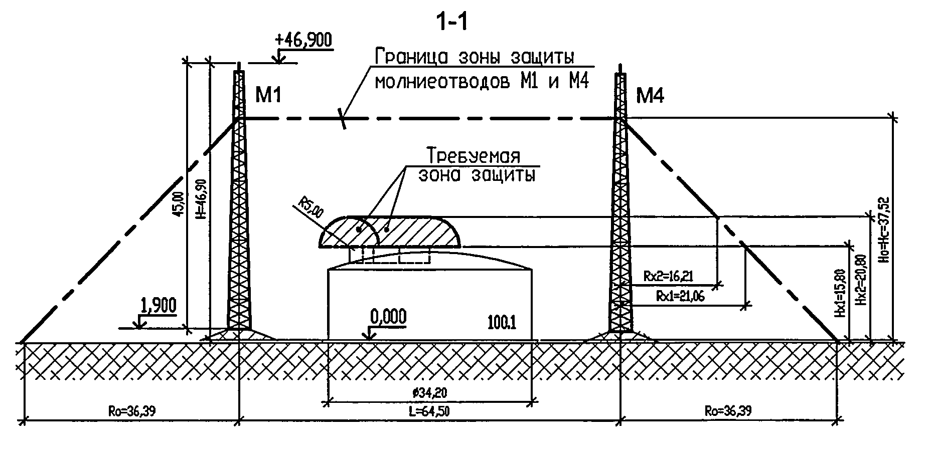
Note! The last remark concerns building codes and regulations, as well as a number of GOSTs and standards related to the development and operation of modern lightning protection equipment.
In conclusion, it should be noted that all the documents reviewed naturally complement each other, covering a complete list of issues related to the arrangement and maintenance of protection systems against natural electricity discharge.
Lightning protection is a set of measures aimed at reducing material damage and injuries to people from lightning strikes.
Lightning protection device on the roof
Dangers from lightning strike:
- complete or partial destruction of structures and buildings, utility networks;
- failure of electrical appliances located in the lightning strike zone;
- injuries and death of living organisms caught inside or near a structure struck by lightning.
What is lightning?
Lightning poses a great danger both to humans and to buildings and structures. Lightning is a high-power electrical discharge that, if hit, can destroy structures and disable electrical appliances and power lines. When constructing high-quality lightning rods, the number of injuries and destruction of structures and utility networks is reduced. The nature of lightning is such that upon reaching the lower layers of the atmosphere, the strike occurs at the highest point within the radius of the danger zone.
The main condition for the formation of thunderclouds is rapid temperature changes and high humidity. Under such conditions, negatively charged clusters of clouds appear in the atmosphere. Due to electrostatic induction on a moving charged cloud, discharges are formed in the atmosphere. Those. Conventionally, it is a capacitor, and the distance between the cloud and the surface of the earth is the gap between the plates. Over time, the electric field strength increases, and tall structures (trees), ionizing the air, reduce the resistivity and provoke lightning strikes to the ground.
Thanks to this property, structures have been developed that are capable of taking a blow and discharging dangerous potential into the ground without damage or fires. Standards for the design and installation of lightning protection: PUE, instruction RD 34.21.122-87, GOST R IEC 62561.2-2014, SNiP 3.05.06-85. Lightning rods are a mandatory measure of protection against lightning strikes if the building is not located in an urban high-rise building, if there is a pond nearby, etc.
Damaging factors of lightning
- Primary. Characterized by thermal and mechanical effects. A direct lightning strike on a building or power line, resulting in the possibility of a fire. Without additional equipment it is impossible to protect against the primary factor. A lightning protection device is required.
Effect of lightning: melting of metal structures (less than 4 mm thick), partial or complete destruction of buildings made of concrete, brick and stone (due to mechanical impact). Rapid heating of structures causes stress in them, provoking explosions (instruction RD 34.21.122-87).
- Secondary. When a discharge hits nearby structures, electromagnetic induction appears in the electrical network, which can damage electrical appliances. To protect against a secondary factor, it is enough to disconnect all electronic devices from the network. This factor is impossible without the manifestation of a primary influence (instruction RD 21.122-87).
Appears as:
- electrostatic induction, expressed by sparks between metal surfaces of structures and electrical appliances. Caused by static charges from clouds onto ground structures;
- electromagnetic induction. Occurs during a lightning discharge due to a changing magnetic field. Induction causes heating of closed circuits and is accompanied by heating that is not dangerous for equipment and people.
Because Lightning is an electric charge, its movement occurs along the path of least resistance. Lightning protection must effectively conduct charges to the ground. When lightning strikes lightning rods, the current goes into the ground without causing damage to buildings inside and outside the protection zone.
The type of lightning protection depends on the type of building, electrical appliances, type of grounding of the electrical network, and the frequency of thunderstorms in the selected climatic region.

Cable lightning protection of a building
Based on the need for lightning protection, buildings and structures are divided into categories:
- Category 1. Explosive and flammable substances are not permanently stored in buildings. The process of processing and storing hazardous substances openly or in unpacked containers takes place. The occurrence of explosions in such structures is accompanied by significant destruction and casualties (RD).
- Category 2: In buildings, hazardous substances are stored in sealed containers. Explosive mixtures are formed only in the event of industrial accidents. The explosion is accompanied by minor destruction, without casualties (RD).
- Category 3. A direct lightning strike causes fires, large destruction of buildings and utility networks, and injury to people and animals. Such buildings must have effective protection against direct lightning strikes (LD).
Protection options
- Active. A new type of protection against lightning strikes. Artificially attracts discharges to itself using a built-in ionizer (ID).

Active lightning protection
Advantages:
- 100% performance;
- eliminating the appearance of a secondary factor of lightning damage.
Flaws:
- Price.
- Passive lightning rods. The peculiarity of the work is that lightning does not strike it in all cases.
Flaws:
- does not work in all cases.
Advantages:
- high reliability;
- low cost of work;
- possibility of construction manually.
Type of protection (RD and GOST R IEC 62561.2-2014)
External type
Protects buildings from the primary factor of lightning - from destruction and fire. Allows you to intercept discharges and deflect the blow to the ground.
During a lightning strike, lightning rods take up the current and conduct it through the system into the ground, where the energy is completely dissipated.

External lightning protection of a building
Requirements for lightning protection - with proper design and installation of the system, complete safety is ensured outside and inside the building.
Types of external protection (instruction RD 34.21.122-87):
- mesh lightning rod;
- lightning rod;
- stretched lightning rod.

Cable structure for protection against lightning strikes
Components of lightning protection (RD and GOST R IEC 62561.2-2014):
- Lightning rods are structures that intercept the discharge. They are made of metal, usually stainless steel, copper or aluminum.
- Descents (down conductors) are metal outlets along which the discharge is diverted from the lightning rod to the grounding conductor.
- Ground electrode is a protective grounding device consisting of conductive materials that are in contact with the ground. It has an external and underground part (ground loop).
Internal type
Protects homes from secondary exposure to electric current. Consists of a number of devices (surge protection devices). The purpose of the devices is to prevent the failure of household electrical appliances from overvoltages in the electrical network, which are caused by lightning strikes.
Overvoltages can be caused by direct (when lightning strikes a building or power line) and indirect (strikes in the immediate vicinity of structures or power lines) lightning strikes.
Based on the type of impact, there are several types of overvoltage:
- 1 type Caused by direct impacts, they pose the greatest danger.
- Type 2 Caused by indirect current shocks, the stored energy is 20 times lower than in type 1 overvoltages.
SPD types according to GOST R 50571.26-2002
- 1 type Capable of withstanding current loads completely from the resulting lightning discharge. Type 1 SPDs are recommended for installation in rural areas with overhead power lines in buildings with lightning rods, in detached buildings located in close proximity to high objects.
- Type 2 Used in conjunction with type 1. The devices are not able to withstand lightning strikes. The permissible surge voltage is 1.5..1.7 kV.
- Type 3 SPD type 3 is used after stage 1 and 2 protection. Designed for installation at the consumer's site: surge protectors, automation devices on household electrical appliances (boilers, etc.).
SPDs are installed together with circuit breakers to prevent burnout and fire in the electrical panel. Long-term overvoltages can damage the SPD.
Input circuit breakers with a rated operating current of less than 25A can act as SPD protection (GOST R 50571.26-2002).
Lightning protection connection is carried out according to two schemes:
- With safety as a priority. The SPD is not destroyed, lightning protection works uninterruptedly. In the event of a lightning strike, it completely disconnects consumers.
- With continuity as a priority. In this case, disconnecting consumers is unacceptable; in the event of a lightning strike, lightning protection is turned off.
When installing devices, a minimum permissible distance of 10 m should be maintained, which ensures the necessary inductance for triggering the machine of a higher stage.

Surge protection device type 1
It is possible to install 1st and 2nd stage SPDs together in one housing (GOST R 50571.26-2002). For each grounding system, SPDs are designed accordingly.
Rod lightning rod
It is installed on the roof of buildings so that the structure is higher than all other points. To maintain the aesthetics of the appearance of the house, the lightning rod should be installed on a separate support (tree).
The following are used as lightning rods (according to the PUE): angle steel 50x50, round steel with a cross-section of more than 25mm 2 .
It is also permissible to use a metal pipe with a diameter of 40..50 mm with sections welded at both ends as a lightning rod.
The number of lightning rods is selected by calculation depending on the size of the structure. For houses with an area of less than 200 m2, one design is sufficient. For buildings with an area of more than 200 m2, it is necessary to install two rods, the distance between which should not exceed 10 m. To prevent current flow into the house, the rod is secured to the roof with insulating materials, for example, wooden blocks, etc.

Excavation work for lightning protection installation
Cable lightning rods
They are used to protect long buildings and structures and high-voltage power lines, i.e. for narrow, long structures.
The main element is a metal cable that is suspended along the entire length of the roof. It is fixed on wooden supports so that there is no contact with the roof surface. At least 2 down conductors are constructed on all sides of the building.
For lightning rods, galvanized steel rope TK with the required design cross-section, but not less than 35 mm 2, is used. The design of cable lightning rods is carried out taking into account the area's icy conditions and the requirements of the PUE. The coverage area of this type of lightning rod has the form of a triangular prism, the upper edge of which will be a tensioned cable on the roof of a building. If the roof has a large slope or several structures of different heights, it is necessary to install lightning rods in order to reduce financial costs.
In the case of rod and cable lightning rods, the distance from the nearest structures must be at least 15 m, or installation is supposed to be on different sides of the building.
Mesh lightning rods
They are made of steel (aluminum) wire with a cross-section of 6 mm in the form of cells with an area of no more than 150 mm 2 so that the mesh does not have points of contact with the roof (6..8 cm from the surface). The mesh is stretched over the entire roof area along isolated supports, with a total size of at least 6x6 m. Down conductors are laid in the corners of the building for every 25 m of the perimeter.
All protruding parts of the structure must fall into the protective area of lightning rods. All ventilation and gas exhaust pipes must be within the lightning protection zone, subject to their mandatory protection with special structures.
Free-standing lightning rods are used in the following cases:
- it is necessary to protect several buildings with one structure;
- It is impossible to install lightning rods on the roof.
Metal lightning rods are used to protect buildings with a height of more than 30 m.
Down conductors
The task of down conductors is to effectively remove the charge from the lightning rod to the grounding structure.
As down conductors, steel wire with a diameter of 6 mm and a metal strip with a wall of at least 2 mm and a width of 30 mm are used.
Provided that the walls do not contain conductive elements, down conductors are fixed along the wall anywhere, subject to the clearance of proximity to doors and windows. To secure the structure, bolting and welding are used.
The number of current collectors is taken based on the number of lightning rods. For rod rods, it is taken equal to the number of rods; for mesh and cable rods, the minimum number is at least 2.
Grounding
One circuit is constructed with a common ground electrode of the electrical network. The simplest design is a triangular ground loop. The tops are vertical electrodes driven into the ground to a depth of 3 m. The optimal distance between the peaks is 3m.
A horizontal grounding conductor (connecting the vertices of a triangle into a single structure) is laid to a depth of at least 0.5 m. The connection is made exclusively by welding.
Installation of lightning protection
For private houses, passive lightning protection rods are most often built.
Preparatory work:
- First of all, it is necessary to carry out all measurements: width, height of the house, estimated protection radius (for rod lightning rods).
- After this, it is necessary to determine the height of the lightning rod and the method of securing it.
- The length of the down conductor is calculated after determining the installation point of the lightning rod. The path from the impact point to grounding must be the shortest, therefore the design of complex structures is not recommended, connections in the form of a ring are prohibited.
- The grounding element, according to PUE and SNiP, must be located at a distance of at least 1 m from the wall of the building, and must not cross pedestrian paths and porches.
After making accurate calculations of the length and design of the grounding, it is necessary to proceed directly to construction and installation work.
Grounding device:
- For grounding, angle steel 50x50 (GOST 8509-93) or strip steel 40x4 (GOST 103-76) is used. Round steel can also be used.
- The grounding loop is made in the form of a polygon, into the vertices of which vertical electrodes with a length of at least 2 m are driven. The vertices of the triangle are connected by welding with strip steel into a single metal structure.
Installation of lightning rod:
- Wooden supports are installed on the roof of the building, installation on which completely eliminates contact of the rod with the roof of the building.
Down conductor installation:
- The last stage is the installation of a down conductor and the connection of all lightning protection elements. The down conductors are mounted on special structures - skates, which also prevent contact with the surface of the house.
- After completion of excavation and construction works, it is necessary to measure the resistance of the lightning rod and whether the obtained values correspond to the calculated values.
- For wooden houses, the process of constructing a lightning rod system is similar. All elements of the lightning protection structure must be 150 mm away from the wall plane.

Lightning protection for wooden houses
Internal protection of buildings and structures
SPDs provide protection of electrical equipment from surge voltages and large inductive loads.
Sources of surge voltages during thunderstorms:
- DLM (direct lightning strikes) into a lightning protection device, strikes into nearby power lines;
- lightning strikes near objects.
SPDs are installed in residential and administrative buildings and industrial facilities. It is mandatory to include an SPD in the power supply circuit in country houses, with one- and two-story buildings (GOST R 50571.26-2002).
Advantages of using SPD:
- reliable protection against surge voltages;
- low cost of devices.
The operating principle of the devices is based on the nonlinearity of the current-voltage characteristic. With a significant increase in voltage, the varistor retains the ability to pass electric current.
The devices fail after several protection activations. The SPD must be checked after each operating cycle.
Fuses are included in the circuit in front of the SPD to protect against heavy currents.
In networks up to 1 kV, three stages of surge protection are provided:
- SPD 1st stage. Class B. Designed for current surges up to 100 kA. Installed in prepared metal cabinets in the input distribution device or on the main electrical panel.
- SPD 2 stages. Class C. The amplitude of pulse currents is 15..20 kA. They are used in areas completely protected from direct lightning strikes. Installation is provided in distribution panels at inputs to buildings and premises.
- SPD 3 stages. Class D. Designed to protect equipment from residual overvoltage currents. Installation is provided directly in front of electrical appliances, the minimum permissible distance is 5 m.
SPD selection parameters according to GOST R 50571.26-2002:
- rated mains voltage;
- long-term permissible operating voltage of the protective device - the highest voltage that can be applied before the protection operates;
- Varistor leakage current;
- protection response time;
- pulse current;
- maximum voltage value when current flows through the SPD;
- classification voltage;
- maximum pulse discharge current – the maximum current load during which the device remains operational.
Maintaining the distance between devices is necessary to guarantee the time delay and provide an impulse to trigger the next protection stage:
- between SPDs of 1st and 2nd degrees - at least 10 m;
- between stage 2 and 3 SPDs – at least 5 m;
- between class 3 SPDs (between each other) – at least 1 m.
Each SPD must be connected to the grounding device with a separate conductor.
A 3-stage surge protector protects devices at a distance of up to 10 m. If it is necessary to protect the network further, the installation of the next device is required.
To reliably protect buildings and structures, it is necessary to use internal and external lightning protection. Surge protection devices will not perform their functions if there are no effective lightning rods.
Video about lightning protection
For country houses, a high-quality lightning protection system is extremely important, because helps prevent the destruction of houses and damage to property. The construction of passive lightning protection systems can be done with your own hands, in accordance with the requirements of the PUE. Active protection requires high qualifications and cannot be installed without the help of specialists.
 (1 ratings, on average: 5,00 out of 5)