Installation of various types of electrical wiring. Hidden wiring installation technology
In practice electro installation work pipeless concealed electrical wiring, carried out by APPVS and APV wires with their laying directly in the thickness of building structures, has become widespread: in gypsum, concrete partitions, under plaster, in voids and channels of ceilings and walls, with embedding in building construction during their manufacture at the factories of reinforced concrete products.
Hidden laying of wires is carried out, observing the following requirements: wires in thin-walled partitions up to 80 mm or under, a layer of plaster is laid parallel to the architectural and construction lines; between horizontally laid wires and floor slabs, the distance should not exceed 150 mm; in building structures with a thickness of more than 80 mm, wires are laid along the shortest routes.
In the premises of brick buildings, as well as in large-block buildings with partitions made of slabs small size, hidden electrical wiring with flat wires is performed as follows: in brick and cinder-concrete plastered walls - directly under a layer of plaster; in the walls of large concrete blocks - in the seams between the blocks, and individual sections - in the gates; in gypsum concrete partitions individual slabs- in furrows, in ceilings made of prefabricated hollow-core slabs - in slab voids or not metal pipes laid on top of floor slabs in floor preparation.
The installation of electrical wiring begins after completion construction works and flooring work.
Technological operations of installation of hidden electrical wiring are performed in a certain sequence. First, mark the route of the electrical wiring, the installation location of the junction boxes for switches and sockets, hooks for lamps. The markup begins with the installation sites according to the project of shields, lamps, switches and socket outlets. Next, mark the routes for laying wires. Flat wires in the horizontal direction are laid at a distance of 100-150 mm from the ceiling or 50-100 mm from the beam or cornice. Wires can be laid in the gap between the partition and the ceiling or beam. Lines to socket outlets are laid at the height of their installation (800 or 300 mm from the floor) or in the corner between the partition and the top of the floor slab. Descents and ascents to switches, lamps are performed vertically. The marking of the installation sites of the fixtures is carried out similarly to the marking of open wiring with flat wires.
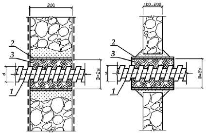
An example of wiring in the channels of a large-panel administrative building;
1 - floor panel; 2 - wall panel; 3 - channels for wires; 4 - niche of the lighting panel; 5 - niche for low-current devices; 6- recess in the panel for connecting wires
Holes in concrete and brick are made with electric and pneumatic tools. In gypsum concrete partitions and brick walls furrows are made by the MVB-2MU1 mechanism. Punch work on brick and concrete is performed with pneumatic chipping hammers, and drilling for junction boxes, plug sockets and switches is performed with KGS crowns.
The preparation of measured segments of flat wires is carried out directly at the installation site. A separating film 75 mm long is cut out at the ends of the wires, and 40-60 mm long at the bends. For three-core wires, after cutting the film in the places of bending, one core is diverted with a half-loop inside the corner. Hidden wiring cannot be fastened with nails. The wires are fastened by “freezing” with alabaster mortar, plastic staples, and cotton tape. Next, the wires are inserted into the boxes, connections, branches are made and their ends are insulated.
When laying wires and cables in the channels of prefabricated building structures, it is not necessary to mark the routes and places for installing devices. Before tightening the wires with a gauge, the suitability of the channels is checked. The diameter of the gauge must be at least 0.9 of the design diameter of the channel. Wherein Special attention pay attention to the presence of sagging and sharp edges at the interface building elements building. Then check the condition of the connecting niches of neighboring wall panels. The niche is made semicircular with a radius of 70 mm, sockets for wiring accessories - with a taper with a diameter of 72-74 mm when installed without boxes and 85 mm - with boxes. The wires are pulled into the channels from the device to the boxes and niches. The tightening force should not exceed 20 N per 1 mm 2 of the total cross section of the cores. With a channel diameter of 20 mm, up to five wires can be tightened, with 25 mm - up to eight wires with a cross section of up to 2.5 mm 2. With a limited number of wires and a short length of straight channels, tightening is done manually, with large numbers- steel wire, previously tightened into the channel, or a device.
An example of wiring in channels is shown in fig.
Modern overhaul often involves the installation of electrical wiring in the apartment. The performance of such work imposes a great responsibility, since not only the correct operation of electricity consumers, but also the fire and electrical safety dwellings.
Wiring diagram
Before proceeding with any wiring work, it is necessary to draw up its diagram. To do this, you need to follow this algorithm:
- You should start by drawing up a plan of the premises of the apartment, which should be made to scale with an indication of the dimensions. Subsequent application of all elements electrical wiring to this plan is carried out with the distribution of consumers into groups, depending on their type and location.
- Determined general power consumers of electricity in the apartment, as well as their distribution in the premises. This is quite easy to do if we take as a basis a similar wiring plan, for example, such as in the figure.

- Determined required amount in each room. If the future interior design is approximately known, then sockets can be arranged based on the maximum convenience of their operation. Otherwise, at least one such device should be provided for every 6 m2 of living space, in kitchens - for every 3 m2. You can not install sockets in the toilet. In the bathroom, their installation is allowed, but this can only be done using devices that have. Such sockets are connected through an isolating transformer, as a result of which their galvanic connection with the general household electrical network is excluded. This solution provides the maximum level of electrical safety, but entails additional material costs.
- The location of powerful household appliances(more than 2 kW), such as electric stoves, boilers, hobs, dishwashers and washing machines, groups of air conditioners, etc. For each of these devices, you need to draw a separate line that has a ground and is connected directly to the input.
- The required number and cross-section of cables, nominal, or are calculated. To make such calculations, you need to clearly determine the number of consumer groups, as well as their power.
Wire section selection
For right choice wire cross-sections, as well as nominal parameters protective devices you can use the following tips:
- For lighting circuits, circuit breakers with rated current 16 A and time-current characteristic type B.
- For individual sockets or their groups, as a rule, switches with a rated current of 20 A are used.
- To connect powerful household appliances, you need to choose circuit breaker, whose rated current corresponds to the power of these consumers. For example, when connecting a device with a power of 5 kW, a switch with a rated current of 25 A is needed.
- It is desirable to connect all consumer groups through an RCD, as a result of which protection against damage is provided. electric shock in case of damage to the insulation. As for powerful electrical appliances, the use of devices that respond to the occurrence of differential currents is mandatory when connecting them.
- The choice of brand and section of wires that must be laid for reliable operation wiring can be done using tables that clearly demonstrate what cable section is needed to connect a group of consumers of a certain power.

In most cases, for the installation of high-quality electrical wiring, it is used, having a cross section of 1.5 mm2 for lighting networks, 2.5 mm2 for connecting sockets, 4 or 6 mm2 for connecting powerful electrical appliances.
Features of the installation of electrical wiring
There are two main wiring options:
- Open way. Currently, it is used quite rarely, mainly in rooms where it is impossible to arrange hidden wiring. Wires are laid in cable channels or special boxes fixed on the walls and ceiling with self-tapping screws or mounting clips.
- Hidden. The most common way. To covertly lay wires, it is necessary to perform wall chasing. This method of wiring installation is associated with the performance of certain construction work, therefore it is performed simultaneously with.
When laying wires in the walls, they should be placed strictly vertically or horizontally, all turns of the wire are performed only at right angles.
Light switches are located next to doorways at a height of 1.5 m or 0.8 m.
It is customary to place electrical sockets in rooms at a height of up to 1 m. It is necessary to pre-lay wires for sockets designed to power wall-mounted TVs, boilers, air conditioners, etc. If this is not done, then later it may be necessary to lay external wires or use extension cords .
It is advisable to start work on the installation of electrical wiring by installing a separate electrical panel in the apartment. An introductory circuit breaker and one modular socket are initially installed in this shield. This solution allows you to turn off the voltage in all circuits of the old electrical wiring and at the same time use a power tool for work.

The procedure for wiring the electrical cable
The wiring in the apartment is as follows:
- Markup. When performing these works, you need to ensure that the wire channels with which parallel-connected sockets are connected are located on the same level with them.
- Chasing walls with an angle grinder or puncher. The depth of each strobe is from 1.5 to 2 cm. In order to properly route the wires in load-bearing walls strobes for them should not be made too deep, as this can lead to a violation of the strength of the building structure. To properly lay the wire, you should be guided by the following requirements:
- distance to the floor is at least 200 mm.
- distance to the ceiling at least 150 mm.
- distance to door or window openings is at least 100 mm.
- Drilling recesses for mounting boxes for sockets and switches, as well as for accommodating junction boxes. To perform such work, special crowns are used.
- Laying wires in strobes. Such work is carried out with the power turned off on a common shield. Laying of wires is carried out using special fasteners or alabaster putty. In this case, it is necessary to carefully monitor the absence of contact between the wire insulation and metal parts building structures.
- Installation of modular elements of the electrical panel.
- Installation of mounting boxes. It is also performed with the help of alabaster. If the apartment has plasterboard partitions, then special socket boxes with appropriate fasteners are used for them.
- IN junction boxes wires are connected in accordance with the developed wiring diagram. It is extremely important to ensure high-quality electrical contact, for which soldering, terminal or bolted connections. Any wiring connections must be made only in the junction boxes.
- and switches. It should not be forgotten that each switch must be installed in such a way that when it is turned off, it is precisely phase wire. When installing lighting fixtures, the phase wire is connected to a contact located deep in the bulb holder.
Electrical wiring is divided into power and lighting, trunk and distribution. To speed up the installation process, wiring harnesses for the same type of products are manufactured separately from the devices.
A bundle is a bundle of wires laid and interconnected, terminated with lugs for connection to circuit elements or products. The bundle combines direct and reverse conductors with industrial frequency currents according to its scheme. The wires used in high-frequency devices are not bundled, as this increases the capacitance between the conductors.
Bundles are made with a sheath for fastening and shielding, as well as without a sheath. The wires of the harnesses are fastened with a bandage of cotton threads, and for the operation of the electrical circuit at elevated temperatures - glass threads followed by impregnation of the bandage with wax or paraffin, sometimes they are fastened with varnish or glue. Shells can be tubular, tape, strip and wicker. Tubular shells can be soft and hard. For soft shells, PVC tubes are used, for hard shells, aluminum tubes are used, which ensure safety under significant mechanical loads. In addition, they perform the functions of electrical shielding.
The manufacture of harnesses includes the following operations:
Preparation of wires by type, color and section;
A piece of wire;
Laying wires in the required combination according to the template;
Bonding of wires with a viscous or dressing sheath, continuity and marking, termination of wires and control of the bundle.
When installed inside and outside buildings and structures, lighting and power wiring with voltages up to 1000 V are made with insulated wires of various grades and sections, as well as unarmored cables with rubber insulation with a cross section of up to 16 m2.
Wiring requirements:
1) in rooms without increased risk of electric shock, wires must be located at a height of at least 2 m, and in rooms with increased or special danger - at least 2.5 m from the floor;
2) the wires are laid along the upper part of the wall at a distance of 150-200 mm from the ceiling, and the wires to the fixtures general lighting- on the ceiling;
3) if the height of the room does not allow maintaining the specified dimensions, then the wires are laid in pipes or hidden in the thickness of the walls of the room. This requirement does not apply to cable runs to light switches and sockets in rooms without an increased risk of electric shock.
Installation rules:
1) in one pipe (box or tray), a closed channel of a building structure, it is prohibited to lay mutually redundant circuits, emergency and working lighting circuits, lighting circuits and power, lighting circuits with voltage up to 42 V with voltage circuits above 42 V;
2) in dry and wet rooms for non-combustible structures, all types of wiring are allowed. In dusty, damp and especially damp rooms, wiring on rollers is not allowed;
3) in especially damp rooms and in rooms with a chemically active environment, it is impossible to lay wires in plastic pipes, under plaster and on rollers;
4) in fire hazardous premises, it is not allowed to lay wires in plastic pipes, on cables and cable wire, on rollers, and in case of combustible structures - under plaster and in vinyl plastic pipes;
5) all conductors of flexible wires and cables (including grounding) must be in a common sheath, braid or have a common insulation. The insulation of wires and cables must comply with rated voltage networks;
6) when choosing wires for electrical wiring, their mechanical strength is taken into account. For example, for aluminum wires the smallest sections for inputs to consumers and wiring to electric meters are taken - 4 mm2, for wires on insulators, the distance between which is up to 6 m - 4 mm2, up to 12 m - 10, up to 25 m - 16 mm2;
7) in places where mechanical damage to electrical wiring is possible, openly laid wires and cables must be protected by sheaths or pipes, boxes, fences.
Installation of electrical wiring is carried out strictly according to project documentation, which describes the brands of wires and cables, installation locations for electrical equipment and lamps, starting and switching devices, places for passages through ceilings or walls, wiring routes, etc.
Installation of electrical wiring involves the following operations:
1) markup;
2) installation of rollers, insulators, brackets;
3) punching furrows, etc.;
4) laying of wires;
5) wire connection;
6) installation of wiring accessories, apartment shields, lamps, etc.;
7) termination of wires and their connection to electrical receivers;
8) performing measurements;
9) commissioning.
After the completion of the installation work, the entire wiring diagram is assembled, the connections are checked for correctness, and the assembled control and signaling circuits are fully tested. Measurements and testing of electrical wiring by personnel assembly organizations during installation, as well as by commissioning personnel immediately before commissioning, are drawn up by the relevant acts and protocols. Let's take a look at each of the above steps in turn. Marking is carried out before the start of plastering, painting and other finishing works. This takes into account the ease of use and maintenance of wiring during operation, subject to the rules of electrical and fire safety.
The marking of the route and the main axes for the placement of electrical equipment and lamps is carried out as follows: marks are made on the floor or ceiling in the form of a black strip 10-12 mm wide and 120-150 mm long.
Marking is done with the help of tape measures, and the lines are beaten off with a cord dyed with blue or dry ocher. The taut cord is pulled back and abruptly released to strike the surface. The location of the fasteners is marked with transverse risks on the broken line. The route for open wiring should be parallel to the lines of building structures.
When marking, determine the location of the transition boxes, fastening of electrical wiring, holes for wires, cables, pipes and niches for shields. After that, the dimensions of the electrical wiring elements and their configuration are specified. At the harvesting site, in accordance with field measurements of the routes, wires are cut for each section of the route.
The ends of wires and cables must be prepared for connections, branches and connections to equipment (luminaires): they are cleaned of insulation, the connection diagrams are checked and the wiring is marked. Prepared sections of electrical wiring are mounted at the installation site using various fasteners.
To protect wires from mechanical damage, into holes for their passage through wooden or brick internal walls houses and interfloor ceilings (see fig.) lay segments of metal or insulating pipes, respectively.
Rice. Laying wires through the wall and interfloor overlap
The ends of the pipes should protrude 10 mm from the walls and ceilings, and the upper end of the pipe laid through the ceiling should rise at least 1.5 m above the floor of the second floor.
The ends of the pipes on both sides are made out with porcelain or plastic bushings. They lay a tube of PVC or semi-hard rubber with a diameter of about 15 mm and such a length that its ends protrude from the bushings by 10 mm. Then a wire is laid through the tube.
In this case, connections and branches of wires are allowed to be made only inside the branch boxes. Routes are laid along the shortest distance between connected devices, parallel and perpendicular to walls, ceilings and columns, with a minimum number of turns, intersections with technological communications and the smallest number detachable pipe connections; away from technological equipment, subjected to frequent disassembly, from places dangerous to service personnel where heating to temperatures above 60 degrees and mechanical and chemical damage are possible; in places convenient for installation, maintenance and repair.
Routes for laying plastic pipes and unarmoured cables on open structures and outdoor installations are selected taking into account their protection by building elements, overpasses from direct sun rays. When the directions of piping and other electrical networks coincide, it is recommended to perform them combined, if this is permissible under the conditions of joint laying, in common channels, tunnels and overpasses.
Bending radii of pipes must be at least 10 outer diameters of the cable at temperatures up to -40 ° C, for areas with low temperatures up to -50 ° C, the permissible bending radius must be at least 20 outer diameters of the cable. When laying technological pipes and electrical wiring jointly along the installed prefabricated structures, the cables are placed below the pipes.
The distance between ducts and pipelines with hot liquids or gases must be: in parallel laying - to pipelines passing from either side, at least 250 mm; when crossing - to pipelines passing under the boxes or from their sides, at least 100 mm; above them - at least 250 mm.
The route line is applied along the walls, columns, ceilings, then the places of attachment and installation of supporting structures and other elements of the route are marked, the correctness of the route breakdown is checked for compliance with its project.
As floors in residential and civil buildings use multi-hollow reinforced concrete panels. The voids of these panels are often used for laying wiring in them. In places where the output of wires to the lamp is required, and for its fastening on the lower floor, passages are punched. The holes are marked so that they are, if possible, in the center of the voids of the panel. To do this, you need to familiarize yourself with the dimensions of the structures, keeping in mind that the panels are standard. In each individual case, it is necessary to first check these distances on the panels used at this object, and then proceed to the marking.
Furrows for hidden electrical wiring are punched in brick, concrete and gypsum building structures. Punching grooves in reinforced concrete is generally unacceptable. To form furrows 8 mm wide and 20 mm deep in gypsum or brick, a furrower is used, in which the working tool is a disk cutter - a steel disk with hard alloy plates arranged radially in the form of teeth. Each insert has a clearance cutting angle of 15°. Work is started after marking the furrows, checking the serviceability of the furrower by testing its work in vain. During operation, the switch handle is held right hand. As the dust container fills, it is cleaned. Large transverse grooves are punched with an electric or pneumatic hammer or a manual puncher. To get furrows correct form after preliminary marking with a furrower, contour lines are outlined, and then the middle part is pierced with a hammer or a manual puncher.
under the outer understand electrical wiring that is laid along the outer walls of buildings, between them on supports (no more than four spans up to 25 m each), etc.
outdoor wiring may be open or hidden. External wiring must be inaccessible to accidental contact or fenced. Unprotected insulated wires external wiring with respect to touching them should be considered as uninsulated (bare).
Indoor networks should be made with insulated wires, while the distance from them to the ground should be at least 2.75 m.
Unprotected insulated wires of external electrical wiring must be located or fenced off so that they cannot be touched by people and animals. Wires laid openly along the walls must be at a distance of at least:
for horizontal laying:
above the porch ……………………………..2.5 m
above the window …………………………………0.5 m
under the window (from the window sill) …………….1.0 m
for vertical laying:
to the window …………………………………..0.75 m
from the ground …………………………………2.75 m
Shielded wires and cables are not subject to these restrictions.
When performing external electrical wiring on supports near the building, the distance from the wires to the window must be at least 1.5 m with a maximum deviation of the wires. In cases where the above safe distances wires must be securely protected from touch.
Above carriageway wires must be suspended at a height of at least 6 m from the surface of the earth (road), and above impassable, footpaths - at least 3.5 m.
The distance between the wires must be: for a span of up to 6 m - at least 0.1 m; with a span of more than 6 m - not less than 0.15 m.
Insulated wires along the walls of the house are laid on insulators or in pipes, and under sheds, where rain or snow does not get on them, on PC-type rollers specially designed for this purpose. The wire suspension height must be at least 2.75 m from the ground. The distance between the points of attachment of wires to insulators installed on the walls should not exceed 2 m.
Laying of wires and cables of external electrical wiring in pipes and flexible metal hoses must be carried out in accordance with the requirements set forth in the section "Installation of electrical wiring in pipes" (note!) in all cases - with a seal. Wiring in steel pipes ah in the ground outside the building is not allowed.
To prevent damage to the wires when throwing snow from the roof of the house, it is better to place the wires not in a horizontal, but in a vertical plane, one above the other. In this case, the distance from the wires to the protruding part of the building must be at least 0.2 m.
Crossing wires with drainpipes and other obstacles is carried out in a steel pipe or hidden in a groove in the wall. At the ends of the passage (bypass), porcelain funnels are installed on both sides with the socket down and filled with insulating mastic.
When installing external electrical wiring on the territory garden plot special attention must be paid to the exclusion of the possibility of contact of wires with tree crowns.
Not allowed to lay outdoor wiring over the roofs of houses.
Installation of open wiring
In the production of open laying of wires and cables along walls, partitions and ceilings, for aesthetic reasons, one should adhere to the architectural lines of the premises - cornices, lines of artistic processing, protruding corners, etc.
So, in rooms pasted over with wallpaper, it is recommended to carry out the upper horizontal wiring above the wallpaper. Wire routes with hidden laying should be easily determined during the operation of the wiring.
In order to eliminate the possibility of accidental damage to wiring during installation work wall lamps, watch, sconce, etc., the choice of the route of hidden laying of wires should be made according to the following rules:
1) horizontal laying along the walls should be carried out parallel to the lines of intersection of the walls with the ceiling at a distance of 100-200 mm from the cornice or beam. Mains of socket outlets are recommended to be laid along a horizontal line connecting socket outlets;
2) descents and ascents to switches, sockets and lamps are carried out vertically at a distance of up to 100 mm parallel to the lines of door and window openings or corners of the room;
3) hidden laying of wires on ceilings (in plaster, cracks and voids of slabs or under a floor slab) should be carried out according to the shortest distance between the most convenient place transition to the ceiling from the junction box to the fixtures. The marking of the routes of hidden wiring, recessed into the grooves of walls and ceilings, can be done in the shortest direction from the inputs to the electrical equipment and lamps.
In rooms without increased danger, the height of the reinforcement suspension must be at least 2 m from the floor to the cartridge. If the ceilings are low and this requirement cannot be met, luminaires are used in which access to the lamps is closed.
It is allowed to lay flat wires in light-resistant insulation (APPV, APPR), protected wires in a metal sheath (APRF) and cables ANRG, AVRG, AVVG, APVG on fireproof and non-combustible substrates (plaster, brick, concrete).
Directly on combustible substrates (wood, chipboard, hardboard) it is possible to lay only APPR, APRF wires and cables with a sheath made of slow-burning materials - ANRG, AVRG, AVVG. Other wires and cables must be laid on a separating layer of non-combustible insulating material- on a strip of sheet asbestos with a thickness of at least 3 mm or a layer of plaster with a thickness of at least 10 mm. The separating layer must protrude from under the wire by at least 10 mm on each side.
Wires are laid along the line of cornices and the ceiling at a distance of 100 × 150 mm from them, fixed at regular intervals at a distance of up to 400 mm from each other with metal strips or nails. Under the metal strips to protect the insulation of the wires, pads of insulating cardboard are placed, which should protrude 2 mm on both sides of the strip. Metal strips are bent in the form of brackets and nailed or fixed in a lock. In damp and damp rooms, washers made of fiber, polyethylene or polyvinyl chloride are placed under the nail heads.
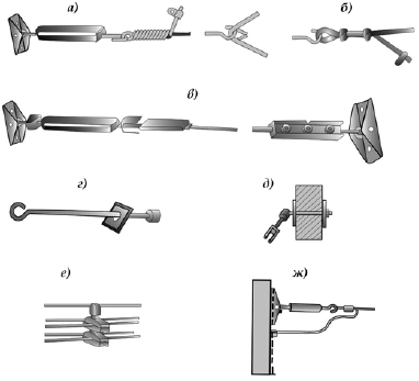
Rice. 35. Methods for fixing wires and cables:
A- steel bracket; b- plastic bracket; V- a plastic strip with a buckle; G- plastic toothed strip
With a parallel arrangement of wires, the distance between them should be 3–5 mm. At the intersection of the wires, 2-3 layers of PVC insulation are applied to the lower wire. At the turn of the wire route in one plane along one wall, the connecting film at the bend is cut out at a length of 60 mm, and the inner core is bent to the center of the corner. When turning the route to another wall or when moving from the ceiling to the wall, the wire is bent without cutting the film, and the bending radius is taken at least 20 mm.
In order to connect wire cores to screw or wedge terminals of apparatus and electrical installations, the insulation is removed from the ends of the wires. In junction boxes, wires are connected by welding, soldering, crimping or screw clamps.
In fire and explosive, especially damp rooms, as well as in attics, electrical wiring is installed in steel pipes, at the ends of which threads are knurled. Zero wire laid in the pipe together with phase.
A package of several pipes is fixed using special support structures and brackets; single pipes are fixed to the surfaces of building structures with brackets, overlays or clamps.
In order to prevent moisture from condensing vapors from accumulating inside the pipes, pipe routes are mounted with a certain slope towards broaching cabinets and boxes.
The length of the route between the broaching boxes depends on the number of bends and should be: with one bend - up to 50 m, with two - up to 40 m, with three or more - up to 20 m. Bending radii for open laying should be at least 6 diameters, with hidden - no more than 10 diameters. Standard sizes bending radii for turning the route at angles of 90°, 105°, 120°, 135°, 150° are respectively 160, 200, 250, 400, 800 mm.
In order to protect the electrical wiring from the effects of an aggressive environment, fire or explosion, the pipeline must have tight connections of all links. The distances between the attachment points - brackets, overlays, fasteners - depend on the diameter of the pipes and are: for small diameters - 2.5 m, for diameters of 50 mm and more - 4 m. Pipelines are attached to the apparatus by welding, threaded connections or special nuts. Welding work on the laying of pipes is carried out before tightening the wires into them.
Light switches install:
¦ in accessible places on the wall near the doors on the side of the handle so that they are not closed by the door when it is opened;
¦ on the left side at a distance of 100 mm from the doorway;
¦ for rooms with damp and especially wet conditions(toilets, baths, etc.) - in adjacent rooms with the best conditions environment;
¦ in attics, in storerooms, basements and other premises - in front of the entrance to them;
¦ at a height of 1.5?1.8 m from the floor of the room.
The installation of socket outlets is planned in places convenient for use, and depending on the interior design. They must be located at a distance of at least 0.5 m from grounded fittings (pipelines for heating, water, gas, etc.). In kitchens, this distance is not standardized.
Requirements for installing socket outlets:
1) installation height in rooms and kitchens is not standardized;
2) the installation height of socket outlets with a grounding contact, intended for connecting air conditioners and electrical appliances that require grounding, is not standardized;
3) sockets of the above-plinth type are installed at a height of 0.3 m from the floor;
4) socket outlets should be installed for a current of 6 A based on: living rooms- one for every full and incomplete 10 m of living space, in kitchens - two, regardless of the area of \u200b\u200bthe room.
Open laying unprotected insulated wires on rollers and insulators is allowed at a height of at least 2 m. The height of the open route of protected wires, cables and wires laid in pipes, metal sleeves, as well as descents to switches, sockets and lamps that are installed on the wall, is not standardized.
Open electrical wiring indoors in places where mechanical damage is possible must be additionally protected.
When laying two or more flat wires in parallel with open or hidden wiring they should be laid flat on the wall (ceiling) next to each other with a gap of 3-5 mm.
Light switches for kitchens, bathrooms, toilets, etc. are placed outside these rooms, and lamps are placed on the wall adjacent to the corridor. As a rule, in toilets and bathrooms, hidden wiring should be used, the wires should be laid in PVC or other insulating tubes.
It is not allowed to use protected wires in a metal sheath and lay them in steel pipes.
The actual installation work begins with marking the installation sites of the apartment panel with an electric meter, sockets, lamps and switches, since the location of these elements determines the beginning and direction of the routes. After that, mark the places for installing junction boxes, avoiding obstacles, punching holes, passing through walls, partitions and ceilings, crossing wires and cables between themselves and with various pipelines, etc.
To attach the wire to the surface of the wall or ceiling, use pieces of steel tape measuring 0.5x10x80 mm or the same strips of tinned sheet.
TO wooden surfaces strips are nailed.
If the wall is made of brick or concrete, then the strips are fixed with screws, screwing them into expansion dowels made of polyethylene, embedded in nests about 40 mm deep, which require a drill or punch with a carbide tip.
Wooden plugs for fixing screws in brick and concrete walls it is not recommended to use, since they, either swelling or drying out in conditions of variable humidity, decrease in size and cease to stick to the wall.
Instead of a spacer dowel, you can use an insulating PVC tube. It is cut along the generatrix and the resulting tape is rolled into a tight roll of such a diameter that it fits into the nest as tightly as possible. When screwing in the screw, the roll will increase in diameter and will be securely fixed in the socket along with the screw.
The screw in the socket can also be fixed with alabaster, having previously screwed a wire in the form of a spiral onto its thread. After the alabaster hardens, the wire forms a metal-shaped thread in the thickness of the wall, which allows you to screw in and out the screw repeatedly.
In nests with a diameter of 10-12 mm and a depth of about 40 mm, metal strips 0.5x10x150 mm in size folded in half can be fixed with alabaster.
The strips are placed at a distance of 400 mm from each other along the wire laying line. The strips closest to the switch, socket or junction box must be 50 mm away from them.
A 15x40 mm rectangle of electric cardboard - pressboard is laid on each strip, and a wire is placed on top of it. The cardboard spacer protects the wire insulation from possible damage the edge of the strip. Having covered the wire with a gasket and wrapped around it with a strip, its ends are connected “in a lock” or fastened with a flat steel buckle.
Flat wires in rooms without increased risk of electric shock may be fixed to wooden walls and ceilings with nails 1.4x20 mm with a head diameter of not more than 3 mm. Nails are hammered every 200-300 mm strictly into the middle of the dividing strip of the wire using a hammer weighing up to 0.2 kg and a mandrel, which excludes damage to the core insulation when driving nails. In unheated wet rooms, it is necessary to put washers made of fiber, polyethylene, ebonite or rubber 1.5 × 1 mm thick under the caps.
With open wiring, sockets and switches are installed on round or rectangular sockets made of wood, chipboard or plastic, fixed to the wall with screws.
Before laying the wire, it is necessary to smooth it out by stretching it through a rag clutched in your hand.
At switches, sockets, in junction boxes, a wire reserve of about 100 mm is left for making connections, branches and connections to equipment terminals.
Before connecting a flat wire to a socket, switch or other device, a separate strip 20 mm long should be cut from its end, and then the ends of the separated wires should be freed from insulation and arranged with a “ring” or “pin” to make the connection.
When changing the direction of the laying line, the flat wire is bent by turning it “on edge” or by cutting out a dividing strip between the cores and bending one of the cores into the corner.
Bending the wire core inside the corner is often difficult even for professional electricians, and they prefer to bend the wire “on edge”, which is easier, but less aesthetically pleasing. Meanwhile, known the simplest trick, which allows you to successfully bend the wire core even without the skill of its implementation. In the place of the required bend, the wire is folded in half, a dividing strip is cut by 5 mm and one of the cores is bent to the side at an angle of 90 °. After that, it remains only to straighten the double-folded wire.
When laying trunk line wires, do not cut them in junction boxes. In each of the boxes, you need to leave a supply of wire in the form of a loop about 200 mm long and continue laying the wires along the wall.
Flat wires must not be used for charging hanging lamps and cartridges lighting lamps. Flat wires are connected to copper stranded wires.
APRF cables and wire with a protective metal sheath are attached to walls and ceilings using metal brackets with one or two legs. The attachment points of the single-leg brackets on the horizontal sections of the wiring along the walls should be located below the cable.
To protect the cable from damage, a pad of electrical cardboard is placed between it and the bracket.
The distance between adjacent brackets should not exceed 500 mm on horizontal, 700 mm on vertical sections of wiring. The brackets closest to the switches, sockets and junction boxes must be 50 mm away from them.
Pieces of wire on walls and ceilings are temporarily fixed with brackets at the ends, at turns and after 1.5 m on straight sections of wiring.
After making connections, branches and connections in accordance with the wiring diagram, the cable is again aligned and finally fixed with brackets.
The laying of the APRF wire has features: on the vertical sections of the wiring, the seam of its shell - the fold - must be adjacent to the wall, on the horizontal ones it is turned down to prevent water from flowing into the shell. When bending the wire, the fold should be located inside the corner. If it is on the side during bending, it will inevitably disperse and the wire will be damaged.
Installation of cable wiring (Fig. 36)
Cable wiring is a type of open wiring and is used to power power and lighting electrical receivers. industrial premises, territories, driveways, warehouses, etc.
bearing element These wires are a steel cable with a diameter of 3–6.5 mm or a galvanized wire with a diameter of 5–8 mm. With the help of anchor and tensioning devices, the cable (wire) is pulled along the route. If the length of the wiring is more than 6 m, then support strings made of galvanized wire with a diameter of 1.5–2 mm are installed. The sag should be no more than 100–150 mm. The wires are connected in junction boxes, and the branches are made in junction boxes suspended on a carrier cable. The cores of the wires are connected by welding, crimping or squeezing.
Rice. 36. Cable wiring installation:
A- ABT wire; b- insulated wires on plastic hangers on a longitudinal cable; V – stranded wires and cables of small sections on plastic clips on a longitudinal cable; G- the same, but fastening with a bandage; d– power and control cables on suspended fir-tree structures fixed on a cable
Rope wiring is carried out with special ABT wires, protected and unprotected insulated wires and unarmored cables suspended from a tensioned steel cable. A steel cable with a diameter of 3.0–6.5 mm or galvanized steel wire with a diameter of 5–6 mm is used. The diameter of the cable depends on the length and load on it.
Anchor or through bolts are used for the end fastening of steel cables.
Unprotected insulated wires (APV, PV, APR, PR) may be fixed on a cable or wire with a bundle of galvanized steel brackets and strips. The distance between the brackets along the length of the route should be 200–300 mm, the thickness of the brackets and strips should be at least 1.5 mm, and the width should be 15 mm. Brackets and stripes must have protective covering from corrosion. At the attachment points, the wires are wrapped in two or three layers. insulating tape or put gaskets made of electric cardboard (roofing material) between the bracket and the wire. The width of the gaskets is chosen so that the gasket protrudes from under the brackets on both sides by 1.5–2 mm.
Insulated wires of the APR, APRV and APV brands, as well as unarmored cables of the AVRG, ANRG, ASRG, AVVG and APVT brands are used for cable wiring.
Rope electrical wiring is also made of special wires with rubber insulation and with plastic insulated with a steel carrying cable built into the wire; in this case, cable wiring is grounded.
Insulating hangers are used, the distance between which should be no more than 1.5 m when hanging a wire or cable from a cable.
Wires and cables with plastic insulation in rooms with fireproof ceilings can be fastened directly to the cable with a plastic perforated tape with buttons or a steel strip “in the lock”. The distance between the fasteners is no more than 0.5–0.6 m.
The luminaires are attached to the anchor devices of the clicks, the wires from them are connected to the main line using flat clamps in a plastic case. The cable can simultaneously serve as a working ground for lamps.
Cable wiring finds the most various uses V national economy And individual construction(for example, to supply energy to summer kitchen, outbuildings, a garage, a workshop or for powering individual electrical receivers and mechanisms with an electric drive that are used on the site). This type of wiring has a number of advantages. First of all, this is the ease of installation work, installation of fasteners and reliable fastening to the bases. Cable guides can be adapted to almost any conditions environment.
Installation of hidden electrical wiring
Hidden electrical wiring is laid under plaster, in closed channels of building structures, voids in large-panel ceilings, walls. It can be replaceable or non-replaceable. Replaceable hidden wiring provides for the replacement of damaged wires between pull boxes.
![]()
Rice. 37. Scheme of wiring in channels panel house
Wires of the APR, PV, PRV, APV, APRV, etc. brands are used for the installation of hidden electrical wiring in plastic, rubber-bitumen and semi-solid pipes.
Laying wires in the voids of walls and partitions completely eliminates penetrating and Finishing work. The wires are pulled using a pre-stretched wire with a diameter of 1.0-1.5 mm. Wires of the APR, APRV, PRV, APV, PV, APPV, PPV, APPVS and PPVS brands are laid in the channels.
Replaceable concealed wiring is laid in steel pipes, which are laid in the channels and grooves of walls and ceilings, followed by sealing them with mortar. For this type of wiring, wires of the APRTO, APRV, PRV, APV and PV brands are used. As noted above, wires are pulled into pipes after welding is completed.
Non-removable hidden electrical wiring is laid under a layer or in a layer of plaster along the shortest path; in this case, wires of the APPV, PPV, APPVS, PPVS, APN and APV brands are used.
The device of passages through walls, intersections of wiring
Passages through internal and external walls, partitions and intermediate floors should be made in a pipe or opening, which would make it possible to replace the electrical wiring. The passages of unarmored cables and wires through fireproof walls and interfloor ceilings should be carried out in metal or insulating semi-solid rubber, polyvinyl chloride tubes (uncut) or in segments of plastic pipes, and through combustible walls - in insulating tubes enclosed in steel segments. The ends of metal pipes must be terminated with bushings or funnels. Installation insulating tubes necessary not only to ensure the replacement of wiring, but also to strengthen the insulation of unprotected wires.
Wires with a folded seam (APRF, PRF, PRFl) are allowed to be laid through wooden walls without additional protection.
Passages can be open and closed. Open passages of wires and cables are carried out in buildings with wooden walls and ceilings. In a brick building, the passage can be made hidden, in a furrow carved into the wall, but not under a layer of plaster.
When preparing passages through walls and ceilings, it is necessary to take into account the environment of the adjoining premises. If the adjoining premises are classified as dry, then the wire in the wall is laid through one hole. When passing from a dry room to a damp, damp or outside, from damp to damp, each wire must be pulled in a separate insulating pipe.
To ensure the flow of water, the holes are made with a slight slope towards a damp, damp room or outside. On the side of a dry room, the hole is framed with an insulating porcelain or plastic sleeve, and on the side of a wet, damp or outside room, with a porcelain funnel. Bushings and funnels are smeared with alabaster or cement mortar so that the collar of the bushing lies tightly on the wall surface, and the outlet of the funnel completely comes out of the wall and is directed downwards. The bushings are put on the insulating tube.
The connection of wires when leaving a dry, damp room to a damp or outside building should be carried out in a dry or damp room at the roller or in a junction box installed at the aisle.
To prevent the penetration of water, the spread of fire, open passages of cables and wires through the outer walls of the premises should be sealed with easily removable fireproof materials after laying electrical wiring ( mineral wool, slag, etc.). Funnels on both sides are filled with an insulating compound, such as bituminous mass. Open passages through the internal walls of normal non-explosive and non-flammable rooms may not be sealed.
Open passages of wires through interfloor ceilings are made in an insulating tube with protection against mechanical damage to a height of at least 1.5 m. When wires are laid hidden through interfloor ceilings, wires are passed in insulating tubes, the exits of which are terminated with porcelain funnels.
When making passes through interfloor ceilings, where protection of the wire from mechanical damage is required when it exits top floor, it is forbidden to use wires of the PRD, PRHD brands (these wires are not laid in steel pipes.)
When making a passage through the interfloor overlap, single-core insulated wires of the APR, APV, APRV, etc. brands are used. Insulated pipes in the passages they should not have breaks along the length and are sealed with the outer edges of the bushings and funnels (they can protrude from them by 4–5 mm).
It is forbidden to make passages in wooden walls at the joints between logs.
Intersections of wires and cables are not recommended. In open wiring, when unprotected wires intersect with unprotected or protected insulated wires (with a distance between them of less than 10 mm), additional insulation must be applied to the unprotected wire: a piece of a whole PVC tube is put on it or 3-4 layers of insulating tape are applied.
IN brick buildings crossings of wires are carried out hidden in plastered grooves - twisted two-core wires of one of the intersected lines are laid in a groove, putting an insulating or PVC tube on them. At the points of entry and exit of the wire from the groove, porcelain funnels are put on the insulating tube.
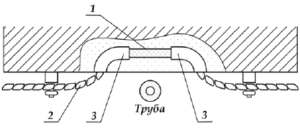
Rice. 38. Pipeline bypass:
1 - wire; 2 - rubber tube; 3 - funnel
In cases where wiring is carried out with single-core wires, each of them is placed in a separate insulating tube.
Around the metal structures of buildings, beams, pipes and especially pipelines with hot liquids, condensation and rust can form, which destroy the insulation. Therefore, when crossing protected and unprotected wires and cables with pipelines (Fig. 38), the distance between them must be at least 50 mm, or wires and cables at the intersection must be laid in insulating or metal pipes embedded in the furrow. If the distance from wires and cables to pipelines is less than 250 mm, they should be additionally protected from mechanical damage at a length of at least 250 mm in each direction from the pipeline.
With open parallel laying, the distance of wires and cables, as well as the distance from the hidden laying junction boxes to pipelines, must be at least 100 mm.
When crossing with hot pipelines, wires and cables must be protected from exposure high temperature
Cable routing on rollers
First, consider the laying of twisted two-core wires of the PRD, PRHD brands (Fig. 39).
Twisted two-core wires of these brands are used for wiring lighting networks only in dry, heated rooms with a normal environment. In this case, rollers of the type RP-2.5, RP-6, RSh-4, etc. are used.
The marking of routes and wiring elements is carried out in accordance with the requirements for open wiring.

Rice. 39. The sequence of operations when attaching wires PRD, PRD to rollers
The rollers are installed at a distance of 800 mm from each other, from the ceiling and from the adjacent wall - at a distance equal to twice the height of the roller, the height from the floor is at least 2 m.
On wooden bases, the rollers are fixed with screws with round head- they do not split the roller when fastened. Screws are screwed into a hole, previously pricked with an awl or drilled with a drill bit of a smaller diameter than the screw.
It is allowed to fasten the rollers with nails, but at the same time, elastic washers must be placed under the head of the nails.
On brick and concrete bases, the rollers are also fixed with screws. The holes are punched with a jumper, the screws are screwed into nylon or polyethylene dowels, pieces of insulating tubes, wooden plugs, a wire spiral.
After installing the rollers, the wires are laid and fixed: at one end the wire is tied to the final roller, then they are pulled and the places of the branches performed on the rollers are marked. Having made a branch, the wire is pulled again and tied to another end roller.
For uniform tension, the wires are first put on the middle intermediate rollers, then on the subsequent ones. The wire is tied to the rollers with cotton braid, cord or thin twine at certain points of the line: on branches, end and corner rollers, on transitions from the ceiling to the wall and from one wall to another, on the ledges of the surface and at the aisles. The wire is only put on the intermediate rollers, but not tied. The nodes are placed under the wire.
If necessary, the third and fourth cores can be woven into the two main wires. Such three- and four-core wires are laid on rollers in the same way.
Single-core insulated wires of the APV, PV, APRV, PR brands are laid on rollers in dry and damp, heated and unheated rooms, under sheds and in external wiring in the same sequence as the two-core wires of the PRD, PRHD brands. In dry and damp rooms, wires are laid on rollers of the RSH-4, RP-2.5, RP-6 type, etc., in damp rooms and outdoor wiring - on rollers of the PC-10 and RS-25 type.
Only one wire is attached to each roller. The wires are tied to the rollers with a "cross", and on the corner and end rollers, where more precise fastening is required, - with a "cross with a clamp". For knitting, soft galvanized steel wire is used, since it is not afraid of corrosion. Diameter steel wire for knitting wires with a cross section of 2.5 mm should be at least 0.6 mm. Wires to the rollers can be attached copper conductors remaining wire scraps. In places of knitting, 2-3 layers of insulating tape are applied to the wire.
The connection of conductors branched off from the main line is carried out by crimping, welding or soldering, then tied to the roller so that it does not experience tension in the form of tension.
Wiring with single-core insulated wires of the APR, PR, PV, APRV brands on insulators is most often performed in damp and especially damp rooms and outdoor installations. Insulators are mounted on walls on steel pins, hooks and supports, on the ceiling, anchors and semi-anchors.
The branching of the wires is carried out only on insulators, to which the wires are attached with galvanized wire. To insulate the wires, it is necessary to make a winding of 2-3 layers of insulating tape.
Wires, with the exception of corner and end wires, are attached to pin insulators using rings or a PVC cord.
On intermediate pin insulators, the wires are laid on the necks or heads, on the corner ones - only on the necks and with outside angle. On the end insulators, it is allowed to install plugs, wires with aluminum and copper conductors (with a cross section of at least 4 mm and at least 1.5 mm, respectively).
When laying single-core insulated wires, the following minimum allowable distances between attachment points must be maintained: for wires with a cross section of up to 10 mm indoors and outdoors - more than 2 m; between the mounting axes - at least 70 mm; from the wire to the floor level in rooms without increased danger - at least 2 m, in all other cases - at least 2.5 m.
Installation of electrical wiring with flat wires
Wires of the brands APPV, PPV, APPVS, APPR and the like are allowed to be laid openly and hidden in dry, damp and damp rooms of a country (garden) house and in outbuildings.
APPV, PPV wires have light-resistant insulation, so they can be used for open electrical wiring directly on the surfaces of fireproof walls, partitions and ceilings (coated with dry gypsum or wet plaster wallpapered). It is allowed to lay wires on wooden and other combustible structures with PVC insulation with a lining under them of non-combustible materials, for example, asbestos with a thickness of at least 3 mm, protruding from each side of the wire by at least 10 mm.
The insulation of flat wires is made of a material that softens and melts at a temperature of 150–190 ° C, and the current-carrying cores of flat wires are at a close distance from each other, so if the insulation melts when heated, a short circuit may occur. In addition, the insulation of flat wires is not protected from mechanical damage, and the presence of hidden damage to the insulation during operation can lead to an accident.
For the above reasons, it is not allowed to use flat wires for open laying in fire-hazardous, especially damp rooms and attics, for hidden laying - in especially damp rooms.
Flat wires are not allowed to be used for charging lighting fixtures and hanging lampholders on them.
With hidden electrical wiring, it is prohibited to embed wires of all brands in building structures, as well as laying flat wires under a layer cement mortar, when in plaster mortars or concrete mixtures add potash, soap naphtha and other components that destroy insulation and aluminum conductors.
Installation of wiring with flat wires consists of the following operations: straightening, marking routes, laying, fastening, bending and crossing, passing through walls, etc.
Editing flat wires is best done this way: clamp one end in a vice or secure it in another way, and then stretch the wire through a cloth or glove. When straightening single-core wires with PVC insulation (PV, APV, etc.), it is not recommended to pull them with great effort, since the insulation may be shifted.
The laying of wires is carried out in sections: apartment shield - junction box - socket; junction box - lamp, etc.
All wire connections are made only in junction boxes, the connection of wires to each other outside the boxes is not allowed.
The wire is cut into pieces equal to the length of individual sections. At the end of the cores, a separating base (if any) is cut out with pliers, 80-100 mm long (a jumper between the second and third is allowed for a three-core wire). The wire is laid with light tension along the entire length of the straight section from the box to the turn of the track. When turning the wire, the separation base is cut out to give the corner the correct shape. After laying, the wire is temporarily fixed at the other end of the section, further straightened, and then finally fixed.
When conducting the wiring, it must be possible to freely make wire connections in junction boxes, boxes for switches and sockets. Such a need arises when repairing or replacing switches, sockets, lamps. Therefore, the ends of the wire with separate cores are inserted into the boxes with a margin of 50–70 mm, after which the wire is fixed at the box. When laying in parallel, the wires must have a gap of 3–5 mm.
If necessary, asbestos gaskets are fixed before the installation of wires, hammering nails into them every 200-500 mm in a checkerboard pattern.

Rice. 40. Fastening wires and cables:
A– APPR to wooden base; b, c– APP and AR to a wooden base; G– APV, APPV to brick and concrete foundations; d, f, w- ANRG, AVRG to concrete and brick bases; 1 - the wire; 2 - nail; 3 - asbestos lining; 4 - a strip; 5 - buckle; 6 - pad; 7 - dowel; 8 - holder; 9 - expansion dowel; 10 - button; 11 - ribbon; 12 - plastic bracket; 13 – cable
With open laying, flat wires are fastened with nails, metal and plastic staples, clamps, strips, tapes, screws, dowels, or glued special glue. Nails with a diameter of 1.4–1.8 mm and a length of 20–25 mm with a cap up to 3 mm are hammered at a distance of 200–300 mm from each other along middle line films between the wire cores with a light hammer, using a mandrel or some other device that protects the wire from damage.
In damp, unheated rooms, it is recommended to place fiber, rubber or similar washers under the nail heads.
Staples made of plastic, rubber, etc. are fixed at a distance of no more than 400 mm from each other. For fastening flat wires, polyethylene staples of the U641, U642 type, etc. are used. In the absence of special polyethylene staples, flat wires can be fastened using metal staples, previously fixed on the asbestos layer, if the base is combustible. Metal strips 10 mm wide and 0.3–0.5 mm thick are cut from a thin steel sheet having anti-corrosion coating. Under the bandage metal strip, it is necessary to place an insulating gasket with a width of 1-2 mm more than the width of the metal strip. The ends of the strip are attached to the lock or buckle. When fastening to a lock, the length of the strip is taken 10 mm more than when fastening with a buckle.
With hidden laying, the wires are fixed in separate places with alabaster mortar; nailing is not allowed.
To preserve the cores and insulation of flat wires when turning the route in the plane of the wall or ceiling at an angle of 90 ° wire bending can be done in the following ways:
1) with open wiring, it is allowed to bring the cores together by flattening the separating base or cutting it along the wire in the middle between the cores. Crossing of veins among themselves in the corners is not allowed;
2) with a hidden laying, edgewise bending is performed: the separating base between the wires, depending on the cross section and the number of wire wires, is cut into 40-60 mm and 1-2 wires are taken inside the corner in the form of a half-loop to prevent their contact.
Bending along the flat side is performed as follows: the wire is bent along the flat side through an angle of 90 ° without cutting the separation base. In this case, the cores should not fit tightly to each other. To prevent such a fit, the next fastening of the wire to the building base is carried out near, but not at the bend.
A wire that does not have a dividing base is bent into an edge with a radius that ensures smooth bending without insulation warpage.

Rice. 41. Crossing and bending flat wires
For hidden wiring, branch boxes, boxes for switches and sockets must be embedded in the wall so that their edges coincide with the surface of the plaster.
Branch boxes must be closed with lids. The dimensions of the boxes should allow the stock of the ends of the connected or branch wires to be placed. For open laying, branch boxes are flat and small. They are installed without lining wooden sockets. If applied metal boxes, bushings made of isolated material or additional insulation is applied to the wire from a rubberized or PVC tape in 3-4 layers.
The separating base when connecting wires to the clamps of switches, socket outlets, lamp sockets, etc., should be cut only in the area necessary for connection, and additional insulation from a rubberized tape should be applied to the ends of the wires.
When laying hidden wires before terminating them wet or dry gypsum plaster it is necessary to check the wiring for the absence of wire breakage and short circuit between them.
Installation of electrical wiring with protected wires
When installing both open and hidden electrical wiring on fireproof and slow-burning bases, all brands of protected wires and cables are laid directly on the bases. On wooden walls, partitions, ceilings and other combustible structures, electrical wiring can be carried out directly on the bases with a lining for wires and cables of fireproof materials or in a continuous layer of fireproof materials.
The method of laying on combustible bases is determined by the material of the sheath of wires and cables. Direct laying of wires and cables on combustible substrates is permitted subject to following conditions:
1) in case of open laying of protected wires and cables, their sheath must be made of hard or non-combustible materials (wires PUNP, APUNP, APRN, PRN, APRF, PRF, PRFl; cables ANRG, NNG, AVVG, VVG, etc.);
2) in the case of hidden laying of protected wires and cables, their sheath must be made only of fireproof materials (APRN, PRN wires; ANRG, PRG cables, etc.).
Cables in PVC and rubber sheaths must be protected from exposure to sunlight and damage by rodents at the points of exit to the outside.
It is not allowed to leave unprotected cable ends that have been brought out and cut, as cracks may form on them due to the susceptibility of insulating rubbers to aging under the influence of sunlight.
Protected wires and cables are laid strictly parallel to the interface lines of walls, partitions, ceilings, door and window openings. Fasten the wiring to the bases of walls and ceilings with metal or nylon brackets. Single wires and cables in horizontal sections are fastened with brackets with one foot, in vertical sections - two or one, on ceilings, corners, at inputs - only two.
With horizontal laying, the distance between the brackets should be no more than 500 mm, with vertical laying - no more than 700-1000 mm (depending on the cross section of the current-carrying conductors). Staples at switches, socket outlets, junction boxes, walkways, etc. are installed at a distance of 50–70 mm and 10–15 mm from the beginning of the bend.
Connection and branching of wires and cables is carried out in junction boxes. Before entering the box, the ends of the wires and cables are cut and prepared for connecting branches inside the box. The length of the cut is chosen so that after fixing the wire or cable, their sheath goes inside the box by 1.5–3.0 mm.
The cutting of cables of the type AVRG and VRG is done like this. Annular and longitudinal cuts of the sheath are made with a knife, then the sheath is unbent, starting from the end of the cable, and removed. Cutting a cable with a lead sheath (ASRG, SRG) is carried out by making annular and longitudinal cuts of the sheath with a knife by about half its thickness. When cutting the sheath, care must be taken not to damage the insulation, therefore it is forbidden to cut through the sheath.
After making cuts, starting from the end of the cable, unbend the sheath to one side and remove it to the annular cut. At a distance of 4–5 mm from the cut of the shell, a bandage of harsh threads, which is coated with adhesive varnish or enamel.
It is forbidden to perform the cutting of ASRG, SRG type cable in a way in which the sheath is notched with a ring, and then broken and pulled together.
The laying of wires PRF, APRF, PRFl with a folded seam has specific features arising from the rigidity of the outer metal sheath. When attaching the wire, the foot of the bracket is always installed under it. When laying wires horizontally along the walls, the seam of the metal sheath should be directed downwards and, if possible, facing the supporting surface, which prevents accidental ingress of moisture into it. When laying wires vertically along the walls, as well as along the ceiling, the seam of the sheath must be adjacent to the supporting surface.
The wire should be bent in compliance with the permissible bending radii, using special tongs of the KT-2 type. The punch and die are selected according to the diameter of the wire. The first few indentations are made by incomplete compression of the tongs, then by compression to failure. Places of indentations are located close to each other so that the subsequent indentation does not overlap the previous one. The wires are bent carefully.
Wires with a folded seam are cut as follows. A seam incision is made and an annular incision is made around the shell from the incision site. In order not to damage the insulation, it is impossible to cut through the shell through. Then the entire shell is deployed with a knife, starting from the incision site. A bandage of harsh threads is applied similarly to the cutting of the ASRG cable. The paper is torn off by hand (not with a knife!) along the entire length of the cut up to the bandage in the direction opposite to winding. Ends the cutting operation. paper filler. The remaining installation operations are performed similarly to the laying of unarmored cables.
To avoid corrosion, it is forbidden to lay wires in an aluminum sheath (AMC alloy), on freshly plastered and freshly painted surfaces. Before laying on such surfaces, the wire is pre-painted with quick-drying oil paints, lacquer or enamel.
Installation of electrical wiring in the attic
The ceiling of the attic space is the roof of the house. In addition, the attic has bearing structures from combustible materials. Premises, floors and structures of which are made of non-combustible materials, are not considered attic.
Electrical wiring in attics is carried out mainly for laying inputs from overhead lines into the building to the clamps of the apartment shield. IN garden houses attic lighting is not required. Installation of electrical wiring, not counting the laying of inputs, in attics made of combustible materials can be called an emergency.
Attic spaces are subject to temperature fluctuations, they are usually dusty, rarely visited by people, have increased fire hazard. Damage to the electrical wiring, accidentally occurring there, can lead to a fire wooden structures, therefore, the device of attic electrical wiring must be treated with special care.
IN attic spaces wiring can be used
¦ open: wires and cables laid in steel pipes, as well as in shells made of fireproof or slow-burning materials at any height; unprotected insulated single-core wires on rollers or insulators at a height of at least 2.5 m from the floor. At a height of less than 2.5 m, they must be protected from mechanical damage. The distance between the attachment points of the rollers should be no more than 600 mm, insulators - no more than 1000 mm, between the wires - no less than 50 mm;
¦ hidden - in walls and ceilings made of fireproof materials (at any height).
In attics, open electrical wiring should be carried out with wires and cables with copper conductors. Wires and cables with aluminum conductors can be used in buildings with fireproof ceilings provided they are laid in steel pipes or hidden in fireproof walls and ceilings. Transit lines in attics up to 5 m long are also allowed to be made with wires with aluminum conductors.
When laying steel pipes, it is necessary to prevent dust from penetrating inside them and connecting (branch) boxes. For this, sealed threaded connections must be used. Pipe connections using threaded couplings without seals are allowed in dry and dust-free attic spaces. Pipes must be laid with a slope so that moisture cannot accumulate in them, including from the condensation of vapors contained in the air.
Branches to electrical receivers from lines laid in attics are allowed provided that both the line and branches are laid openly in steel pipes, hidden - in fireproof walls and ceilings.
Switching devices in circuits supplying lamps installed directly in attics should be placed outside them, for example, at the entrance to the attic.
Steel pipes, lamp housings and others metal constructions electrical wiring in the attic should be zeroed.
It is forbidden to lay any non-metallic pipes in attics - polyethylene, polypropylene and vinyl plastic.
Basement wiring installation
Cellars and cellars are made mainly of fireproof materials and structures. The floors in these rooms are usually conductive - earthen, concrete, etc. Depending on the condition of the soil, ventilation efficiency and relative humidity air, basements are classified as damp and especially damp rooms, and according to the degree of danger of electric shock to people, they are especially dangerous. Therefore, increased requirements are placed on electrical wiring in basements.
Open wiring with unprotected wires directly on the bases, on insulators and rollers should be carried out at a voltage of up to 42 V at a height of at least 2 m from the floor level, at a voltage above 42 V - at a height of at least 2.5 m. The height of the open laying of protected insulated wires and cables in pipes from the floor level is not standardized.
For concealed wiring, it is forbidden to use steel pipes with a wall thickness of 2 mm or less.
The technology of mounting wires and cables directly on bases, on rollers, insulators and in pipes is described in the relevant sections.
Installation of electrical wiring in garages and workshops
According to the fire safety rules (PPB-08-85), it is impossible to refuel a car in the garage, carry out repair work associated with washing parts with kerosene or gasoline, painting or touching up a car, you cannot store a supply of gasoline in a volume of more than 20 liters, etc. If these requirements are violated, then according to the explosion safety conditions, the garage is classified as class B-la, in which normal operation explosive mixtures of flammable liquid vapors with air are not formed and are possible only in case of an accident or malfunction. In the premises of this class, wiring must be carried out in gas pipes, and all lighting must be explosion-proof. Fuses and switches for lighting circuits are installed in an explosion-proof room or outdoors. Cable passages through the wall (Fig. 42) can be made through pipe sections sealed with fibrous filler. If the power input is made by a cable laid in a pipe, sealing is carried out using a pipe gland.
Rice. 42. Cable entry into an explosive room through a wall:
1 – cable; 2 - pipe; 3 – seal with fibrous filler
Let's pay attention to the following. Explosion-proof lamps have significantly big sizes than conventional ones, and are not suitable for installation in garages, the ceilings of which, as a rule, do not exceed 2.5 m. However, luminaires installed with outer side in front of non-opening transoms with double glazing. With single glazing of transoms, luminaires must have protective glasses or glass caps.
The luminaires can be located in niches of walls with double glazing and ventilation of niches with outside air. In these cases, it is allowed to perform lighting with lamps without explosion protection, i.e., general purpose.
Since the use of portable lamps in hazardous areas should be limited, it is advisable to make the illumination of the garage the same as in residential premises - 12–16 W per 1 m2.
To power portable electrical receivers, use flexible wire with copper conductors with rubber insulation in a rubber oil and petrol resistant sheath that does not spread combustion. The use of wires or cables with polyethylene insulation or sheath is prohibited.
Sockets of portable electrical receivers must also be made in explosion-proof design or removed from the explosive zone.
In accordance with the Fire Safety Rules, for general lighting of concrete, stone and metal garages, finished inside with non-conductive materials, including floors, it is allowed to use permanently installed (on the ceiling or walls) indoor lamps with voltage up to 220 V.
Lighting of all types of metal garages with conductive walls and floors is allowed permanently installed luminaires closed version with voltage up to 42 V and portable lamps - up to 12 V.
In garages, only factory-made fixtures should be used.
Zeroing in lighting networks is carried out by zero protective conductor laid in common shells together with phase conductors.
If the unheated workshop room is separated from the garage, which is an explosive class B-la room, by a wall without openings, then it is an explosion and fire safe room. For power supply of electrical consumers located in the block outbuildings, air or cable line and the entrance to the workshop is arranged. A shield is mounted in the workshop room, on which start-up and protective equipment is placed, serving the garage, workshop, and other outbuildings, including premises for livestock and poultry.
The location of the starting and protective equipment of the garage and other utility rooms in the workshop makes it possible to avoid more complex options power supply of buildings of the economic complex. In addition, the concentration of starting equipment on one shield for the entire block of outbuildings does not create difficulties in operation. If at night it is necessary to visit a garage or other premises, a circuit breaker is turned on on the switchboard located in the house. They open the workshop and turn on the lighting on the workshop panel with the appropriate switches where it is needed. The lighting of the garage is carried out by lamps installed in the niches of the walls in front of the glazed transoms. Suppose that the total power of the fixtures is 350 W (7 lamps of 50 W), the power of a portable lamp is 25 W for a voltage of 12 V.
Devices for turning on and protecting the garage lighting network, a step-down transformer, a device for protecting and turning on a portable lamp are installed on a switchboard located in the workshop on any of the walls, with the exception of the wall that is common with the garage.
Installation of electrical wiring in pipes
Electrical wiring in pipes (steel and plastic) is carried out only in cases where the use of other laying methods is not recommended. Pipe wiring is used to protect wires from mechanical damage, to protect insulation from adverse environmental conditions. To protect against mechanical damage, the pipeline can be made leaky, and to protect the wires from external environment it must be waterproof and dustproof. The tightness of the pipeline is ensured by sealing the joints between pipes, their connection to junction boxes and various electrical appliances.
To avoid overheating of steel and plastic pipelines, they should be laid below the pipes of the heating system. When crossing with them, the distance to the electrical wiring pipes must be at least 50 mm, and with parallel laying - 100 mm.
Steel pipes are laid so that moisture cannot accumulate in them. To drain moisture that can condense in pipes, they are laid on horizontal sections of the route with a slight slope towards the box.
Unprotected insulated wires of the APRTO, PRTO, APV, PV, etc. brands can be placed in steel and plastic pipes.
Installation in pipes should be carried out in such a way that, if necessary, the wires can be removed and replaced by others. Therefore, if there are 2 bending angles on the pipeline route, then the distance between the boxes should not exceed 5 m, and on straight sections - 10 m.
Connections or branches of wires in pipes are prohibited, they are made only in boxes.
Installation of electrical wiring in steel pipes can be carried out with open, hidden and outer laying. Steel pipes are used when laying wires without pipes is not allowed and non-metallic pipes cannot be used.
Pipes must be free of rust, dirt and burrs before installation. To protect the shell of wires and cables from corrosion, pipes laid openly are painted on the outside (preferably also inside) or galvanized pipes are used. When laying in concrete (concealed laying), the pipes are not painted on the outside for better adhesion of their surface to the mortar.
Crushing (corrugation) of pipes when bending at corners is not allowed.
It is not recommended to bend the pipe at an angle of less than 90 °, since it will be difficult to drag the wiring through with a complex configuration of the pipeline and its long length. For this reason, pipe bending radii are limited: when laying pipes hidden, the bending radius must be at least 6 outer diameters; with one bend or open laying - at least 4 outer diameters; when laying a pipe in concrete - at least 10 outer diameters.
With open laying, the distance between the fixing points of steel pipes in horizontal and vertical sections depends on the diameter of the pipes being laid. Pipes with a diameter of 15–32 mm are fixed after 2.5–3.0 m, at bends - at a distance of 150–200 mm from the angle of rotation.
In open laying, pipes are attached to support structures staples, overlays and collars from strip steel.
When installing wiring, the ends of the pipes after trimming are cleaned of burrs, countersunk and terminated with metal or insulating bushings that protect the wire insulation from damage at the point of entry and exit from the pipe.
In damp, especially damp, fire hazardous premises, outdoor installation and in attics, with open and hidden laying, steel pipe joints must be sealed. The sealing of the connection points and the points of entry into the boxes must be carried out with standard threaded couplings with a seal with tape or hemp on drying oil, minium.
When laying steel pipes hidden in dry and damp rooms, in walls, ceilings and floors, it is also necessary to seal the joints and the places where the pipes enter the boxes.
When laying open in dry, dust-free rooms, the pipes themselves are connected, as well as their connection with boxes, without seals: sockets, cuffs on screws and bolts, sleeves from pipe segments or rolled from sheet steel, welded to the pipe at several points.
Plastic pipes have sufficient mechanical strength, smooth surface. When using them, the probability of shorting the wires to the ground decreases, labor costs during installation are reduced (operations such as threading, painting, etc. are excluded)
Plastic pipes laid openly are fastened with brackets that allow free movement of pipes when temperature change length. The distance between the brackets is taken as follows (see table):
The distance between pipes laid in parallel must be at least 65 mm with a diameter of up to 25 mm.
Staples are fixed with screws or using nylon dowels.
Greetings, dear readers! We continue our acquaintance with electricity. In this article, I will tell you what is open wiring and how it is laid.
At all, open type electrical wiring is the oldest and less complex to carry out. With this option, the wires are laid directly along the walls and ceilings (on their surface). This is where the name of the type of wiring came from - open, because it is laid openly, right in front of you.
There are many ways to lay this type of wiring, and the oldest and simplest of them is laying on the surface (nailing to wooden wall or using insulator rollers).
This method is the simplest and oldest, but not aesthetic, because this violates the aesthetics of the room, since for fire reasons it is impossible to close the wire. Thank God there are many ways to do it these days. open wiring without violating the aesthetics of the room.
Ways to do it
Let's start with the most common of them -. I wrote a separate article about this. Now let's go over the surface.
This method is less aesthetic than floor plinth and a cable channel, but it is much easier to make turns with corrugated pipes, and it is also easier to mount them.
Write comments, additions to the article, maybe I missed something. Take a look at, I will be glad if you find something else useful on my site. All the best.
 (1 ratings, on average: 5,00 out of 5)

