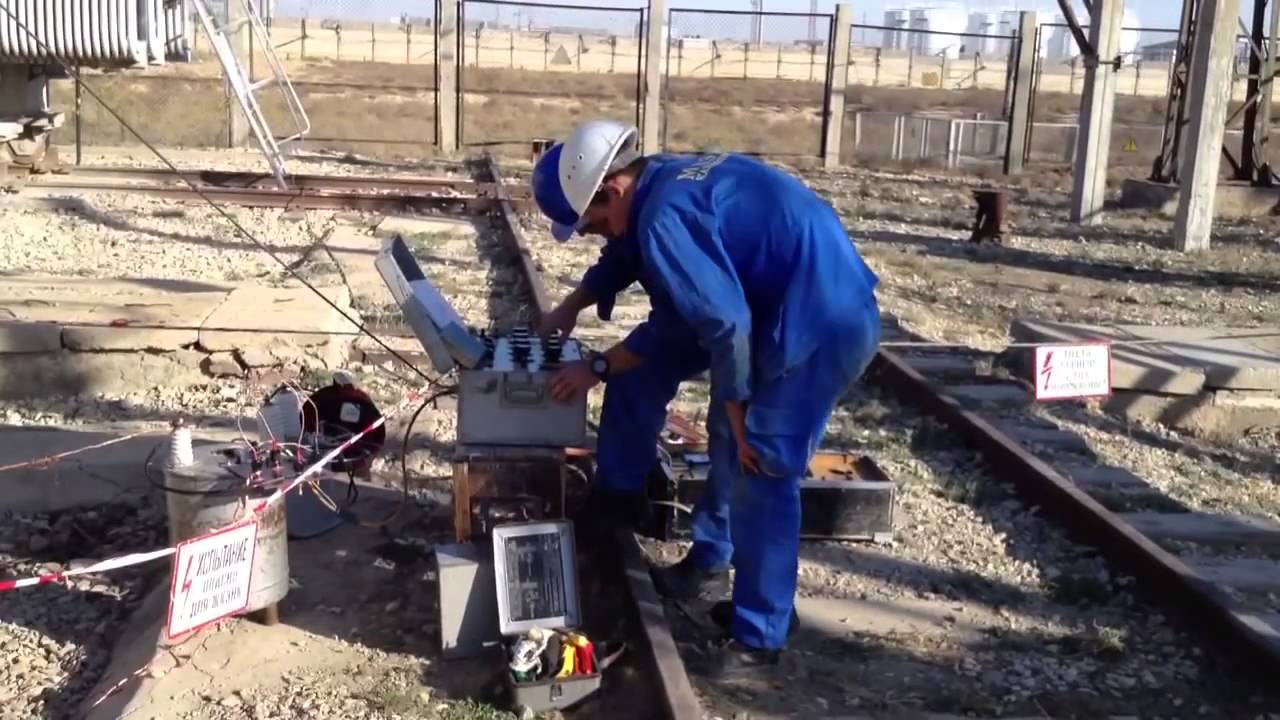
Burning cables - commissioning work during installation of electrical installations
3. BURNING OF INSULATION AT THE LOCATION OF DAMAGE
3.1. Requirements for the methodology and main stagesburning process
The main purpose of burning defective insulation is to reduce the transition resistance at the defect site, which allows the use of methods that provide fast and accurate OMP. For the most part effective methods OMP requires that the transition resistance at the point of damage be reduced to tens or even fractions of units of Ohm. In addition, for the most effective use of the induction method, it is highly desirable to “translate” a single-phase damage into a two-phase one. All this is achieved by burning insulation in the defective area using special installations.
Burning is carried out due to the energy released in the breakdown channel. In this case, the insulation becomes charred at the site of damage and the contact resistance decreases. It should be noted that burning also allows you to directly and easily detect damage in end grooves and on exposed cables by heating, the appearance of smoke and a burning smell.
The cost, dimensions and weight of the burning device are decisive for the entire complex of equipment used in the process of searching for cable damage. In most cases, burning accounts for the main components of labor and time costs for OMP cables. Incineration methods and devices must meet the following requirements:
1) ensure charring and destruction of the insulating material at the site of damage. In addition, to use most OMP methods (pulse, induction, etc.), it is necessary to create a conductive bridge by melting metal particles from the core and sheath and reducing the transition resistance to units and fractions of an ohm. To apply the acoustic method, it is necessary to destroy the conductive bridge or eliminate its formation;
2) have minimal impact on intact insulation;
3) provide for minimum values of capital and operating costs;
4) have minimal dimensions and weight;
5) provide safe conditions operation. As will be seen from what follows, optimal mode burning is realized by sequential alternation of burning stages. Each stage must provide separation maximum energy in the minimum time in the damaged area of insulation and ensure the highest combustion efficiency
Where W pr - energy released at the site of damage; W n - energy losses in circuit elements.
The main type of insulation for power cables is paper-oil insulation. A number of characteristic properties of this insulation necessitate the creation of special devices that provide a more or less long-term release of energy at the site of damage. In other types of insulation (polyethylene, polyvinyl chloride, etc.), the burning conditions are much easier. Therefore, let’s consider burning paper-oil insulation. The insulation of three-core cables with voltage 1...10 kV must meet the following requirements:
The insulation thickness of the core of 35 kV cables with separately leaded cores is 9…11 mm.
The insulation consists of strips of cable paper thick
0.12 mm (less often 0.17 mm) and about 15 mm wide, applied with a gap of 0.2...0.3 mm so that the next layer overlaps the gaps of the previous one. For example, cable core insulation
6 kV consists of 18...20, and belt - of 7...8 tapes. Paper fillers are used to give the cable a rigid, round shape before applying a metal protective sheath. Paper insulation impregnated under vacuum with an oil-rosin composition.
Electric strength of intact cable insulation
6 kV is 200…250 kV, DC test voltage is 35…40 kV. Therefore, in the vast majority of cases, clearly defective areas are damaged, and the length of the defective area is measured in fractions of a millimeter, less often in millimeters. The initial breakdown of cable insulation only sometimes has a radial character, i.e., passing along the shortest path between the core and the sheath or between the cores. Because tension electric field in the cable has both radial and tangential components, the breakdown path is usually significantly longer than the shortest distance between the electrodes. During breakdown, due to thermal energy, decomposition of the impregnating composition occurs, accompanied by gas release. In this case, on the one hand, the impregnating composition is displaced from the breakdown path, which reduces the electrical strength; on the other hand, the pressure in the resulting cavities rises, increasing this strength. After the breakdown, the pressure decreases and the cavity begins to fill with an impregnating composition. As a result, a second breakdown, compared to the first, usually occurs at a slightly lower voltage. With oily impregnation, the breakdown voltage may even increase slightly. The movement of mass particles also contributes to some displacement of the breakdown path. Repeated breakdowns lead to the formation of a more or less stable discharge channel. It is advisable to call this stage of the process the initial stage of combustion.
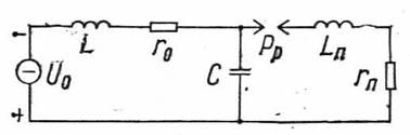
The location of the damage at this stage can be represented by the equivalent circuit shown in Fig. 3.1, A, Where WITH- cable capacity; R R - a spark gap whose breakdown voltage corresponds to the breakdown voltage of the discharge channel; r d - resistance, conditionally reflecting the release of active energy when discharging the cable capacitance to the discharge channel; U o and r o - voltage and internal resistance of the source connected to the cable line.
|
|
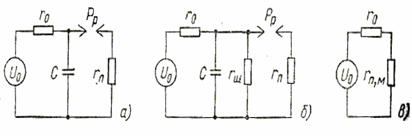
Rice. 3.1. CL replacement circuit for various stages burning
for damaged insulation: a, b, V- primary, intermediate
and final stages respectively
As studies show, during a breakdown, the channel resistance is significantly less than the wave impedance of the cable. Therefore, after a breakdown of the insulation of a charged cable, an oscillatory discharge process occurs with energy consumption for active losses in the discharge channel and cable. Power cable attenuation coefficient a = (2.5…5) 10 -4 s 1/2 / km. Taking into account the indicated value of a and experimental data, the almost complete attenuation of the oscillatory discharge process for cables with a length of 0.1 to 5 km
occurs in 50...300 μs. It is not possible to control active losses in the conductors and cable insulation, but in an equivalent circuit, that part of the active energy that is released in the discharge channel can always be equivalent to losses in such resistance r n, when capacitance C is discharged, the same amount of heat will be released as under actual conditions.
If breakdowns are repeated for a sufficiently long time, the decomposition of the impregnating composition near the discharge channel leads to drying of the area adjacent to it, which causes charring of the channel walls. The equivalent circuit for this intermediate combustion stage is shown in Fig. 3.1, b, Where r w - resistance shunting the discharge channel; r e = r O r w/( r o + r w) - equivalent circuit resistance. As the walls of the channel and the adjacent insulation area become charred, the resistance value r w decreases. When burning at an intermediate stage, the discharge energy and heat generated in the resistance are used r w (in charred insulation).
Further charring leads to the cessation of discharges and the formation of a more or less stable conductive bridge. Substitution diagram for this final stage burning is shown in Fig. 3.1, b, Where r p, m - resistance of the conductive bridge between the core and the sheath (or between two cores) of the cable.
To use the induction method for determining the location of damage, as already noted, it is necessary to reduce the value r p, m to units and even fractions of a unit of Ohm. To satisfy the last requirement, complete charring of the channel is not enough. It is necessary to create not a carbon, but a metal conductive bridge between the core and the cable sheath (or between two cores). This is achieved by melting metal particles from the surfaces of the core and shell, which gradually fill the discharge channel. Melting occurs at currents of several tens of amperes.
3.2. Burning through insulation from a DC source
voltage
Ideal constant voltage source. It is convenient to carry out the analysis using equivalent circuits presented in Fig. 3.1. At the initial stage of burning (Fig. 3.1, A) the process proceeds as follows. From the source U o The cable capacity is charged with a time constant r o WITH. The voltage applied to the insulation varies according to the law:
![]() (3.2)
(3.2)
up to breakdown voltage U pr of the discharge channel (discharger). After a breakdown, the cable capacity is discharged through the defect location. Approximately (without taking into account the cable inductance) we can write:
![]() . (3.3)
. (3.3)
 The internal resistance of the source is kOhms, and more often - many tens of kOhms. Resistance r P< 50 Ом, поэтому r o > r n and charging the cable capacitance takes many times longer than discharging. The change in voltage at the breakdown site during the initial period of combustion is shown in Fig. 3.2, A. Current flows in the power supply circuit
Current flows at the breakdown site
![]() . (3.5)
. (3.5)
During the initial period of burning, the breakdown voltage differs little from the source emf. Let for certainty U pr =
= 0,99U O. Then, according to the equation, the voltage applied to the insulation reaches the breakdown voltage of the discharge channel after a time t’= 5 r 0 WITH.
During one charge cycle, the source consumes energy
 . (3.6)
Part of it is converted into heat released in the internal resistance of the source:
 , (3.7)
and part is spent on charging the cable capacity
![]() . (3.8)
. (3.8)
From the last expression it follows that, regardless of the resistance of the source, both indicated parts of the energy are equal to each other. The energy stored during charging is converted into heat during the discharge process in almost the time t”³ 5 r P WITH. Indeed, taking into account the value i etc
 . (3.9)
Thus, with a non-inductive source, at the initial stage of the combustion process, no more than half of the source energy is usefully used, i.e., the efficiency (h) is about 50%.
Similarly for U pr = 0.9 U o we get t" = 2,2r O WITH and h = 44.4%. The repetition period of discharges at the initial stage of burning is determined internal resistance source and cable capacity and is (3…5) r O WITH. The discharge time is many times less than the repetition period.
The ratio of charge time to discharge time is called duty cycle, which is defined as
If we take the transition resistance at the moment of breakdown
r n = 30 Ohm, then for installation with internal resistance r 0 =
= 300 kOhm duty cycle l = 10 4, i.e., only in one ten-thousandth of the burning process time does energy release occur at the breakdown site. In other words, under these conditions active part the process is approximately 1 s per 3 h of burning.
In the process of repeated breakdowns, gradual charring of the discharge channel and adjacent insulation areas occurs. This leads to a decrease in discharge voltage. With the same combustion source, the frequency of breakdowns increases (Fig. 3.2, b). Let U pr = 0.43 U oh then time t’ = r 0 WITH and the frequency of breakdowns increases by 3-4 times. Carbonization of the walls of the discharge channel also leads to a decrease in its resistance, which becomes comparable to the internal resistance of the source, and the initial stage of combustion already passes into the intermediate stage (Fig. 3.1, b).
Voltage at the arrester:
![]() . (3.11)
. (3.11)
Bye r w >> r 0, the burning process differs little from that described above. When the shunting discharge channel resistance becomes comparable to r 0, two phenomena should be taken into account. On the one hand, the flow of current through the walls of the discharge channel is accompanied by the release of a significant part of the energy used for further charring of the insulation. On the other hand, the maximum voltage on the discharge channel decreases and, with the same source, may be lower than the discharge voltage. In fact, for example, when r w = 0.2 r 0, the voltage on the discharge channel decreases by 6 times.
Under these conditions, the combustion efficiency begins to decrease significantly. In the absence of discharges in steady state, the efficiency will be
![]() . (3.12)
. (3.12)
When r w = 0.2 r 0 H value = 16.6%. The only way to increase the combustion efficiency is to reduce the internal resistance of the source, i.e., replacing the combustion source. At r w = r 0 H value = 50%. In addition, the maximum voltage on the discharge channel increases to U 0 /2. If this value is higher than the breakdown voltage of the channel, then discharges occur, and consequently, the burning efficiency further increases.
From the above it follows that it is necessary to change the parameters of the burning source during the burning process itself, since the creation of a high voltage source with low internal resistance is difficult due to the very large mass of such a source. In practice, after the discharge voltage has been reduced, provided by setting a high voltage with a high internal resistance, you should connect another source with a lower voltage and, accordingly, lower internal resistance. At the same time, the burning efficiency increases and the duty cycle of the discharges decreases, i.e., the burning process accelerates.
Further destruction of the insulation during burning leads to the cessation of discharges and the formation of a relatively stable conductive bridge at the site of damage. The equivalent circuit for this final combustion stage is shown in Fig. 3.1, V. Analyzing this stage similarly to the previous one, we obtain
![]() . (3.13)
. (3.13)
The dependence is graphically presented in Fig. 3.3.

Rice. 3.3. Dependence of combustion efficiency on relative conductivity
bit channel
Ideal source with series inductance. To increase the efficiency of direct current burning, it is proposed to include a choke between the constant voltage source U o and a damaged cable. The combustion diagram for the case under consideration is shown in Fig. 3.4.

Fig.3.5. Changes in cable voltage and circuit current
in the diagram of Fig. 34: A- b > w o; b-b< w о
The oscillatory mode is most effective for burning, since in this case (Fig. 3.5, b) the voltage on the cable can reach double the source voltage, and the voltage changes with frequency , and the current in the circuit changes with the same frequency
![]() , (3.14)
, (3.14)
![]() , (3.15)
, (3.15)
where is the natural frequency of the circuit; b = r o /2 L- damping decrement; a = arcsin b/w 0 . Losses in this circuit:
 , (3.16)
and the burning energy is taken to be equal to the energy stored in the container,
![]() . (3.17)
. (3.17)
The expression for combustion efficiency can be represented in the following form:
 . (3.19)
The voltage on the cable reaches highest value by time w t m= p+a, then the expression after transformations will look like
 . (3.20)
For real installations, the quality factor of the circuit (Fig. 3.4, b)
Q o = w 0 L/r o >> 5. In this case a< 6°, a W n* £ 0.177. Accordingly, the combustion efficiency h ³ 84%.
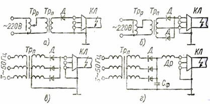
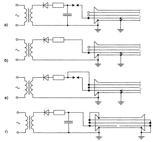
Rice. 3.6. Schematic diagrams burning through insulation using
rectifier units: a- half-wave rectification;
b- full-wave rectification; V- three-phase rectification;
G - three-phase rectification with series inductor
With an increase in the quality factor of the circuit to ten, the efficiency increases to 92% (in the absence of a choke, the maximum efficiency does not exceed 50%). Discharges will follow over time t m"p/w = = 1/(2 f). If the oscillation frequency f= 50 Hz, then t m£0.01s, i.e. burning will be effective.
A schematic diagram of burning insulation using rectifier units is shown in Fig. 3.6. When burning through defective cable insulation from rectifier units, it is necessary to take into account the leakage inductance of the supply transformer.
3.3. Burning insulation on alternating voltage
Non-resonant burning (Fig. 3.7) is carried out using a step-up transformer, the secondary winding of which is connected directly to the damaged core and sheath (or other damaged core), and the primary winding is connected to the industrial frequency network.
In Fig. 3.7: Trp - step-up transformer; L And r 0 - leakage inductance and active resistance transformer Trp, reduced to the secondary winding; WITH- CL capacity; r n is the transition resistance of the discharge channel; L K and r K - inductance and active resistance of the cable; r p, m - resistance of the conductive bridge at the defect site.
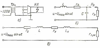
Rice. 3.7. Non-resonant burning schemes:
a- principled; b- substitutions for initial and;
V- final stages
Voltage amplitude on the cable (arrestor RR)
 , (3.21)
where w = 2p f— circular frequency; I max - current amplitude in L.C.r o -contour (Fig. 3.7, b).
Significant specific capacity power cables leads to the need to consume large currents I max to ensure sufficient voltage U c , max.
So, voltage transformer U max = 50 kV at L =
= 200 Hn and r 0 = 10 kOhm will provide voltage on a three-core cable of 6 kV with a cross-section of 70 mm 2 and a length of 3 km U c ,max = 2.66 kV, which is only 5.3% of the source voltage with a power consumption of 20 kV. A.
For cables longer than 0.5 km, non-resonant burning is completely unsuitable at the initial stage. For short cables it can be justified only in the absence of rectifiers. From the same transformer as in the previous example, on a cable of the same type, but 0.4 km long, it is possible to provide about 50% of the source voltage with a consumption of 27 kVA.
In practice, when burning on alternating current, first slowly, using adjusting devices, raise the voltage by primary winding burning transformer. Therefore, before the first breakdown, the voltage on the discharge channel can be considered as steady. The first breakdown occurs at a moment corresponding to the voltage on the discharge channel approaching the maximum. The discharge in nature and duration corresponds to the case considered above when analyzing the circuit in Fig. 3.1.
Repeated processes of charging the cable capacitance after fast discharges occur similarly to the switching process rLC- circuits for sinusoidal voltage.
Two more free components are superimposed on the forced sinusoidal voltage component with frequency w. When r o ³ 2Ö L/C they are aperiodic in nature with different time constants. At r O< 2ÖL/C oscillatory components with frequency w o = Ö1/ L.C. - r o /4 L 2 are shifted in phase with each other by a certain angle a, but attenuate with the same time constant.
The maximum voltage on the discharge channel depends on the moment of switching on (the moment of the previous breakdown) and the relationship between the frequencies w and w o.
In cases where w >> w o, overvoltages occur and the probability of breakdown of the discharge gap increases.
A decrease in the frequency w o, other things being equal, increases the duty cycle of the discharges. If we add to this the practical impossibility of ensuring a stable value of angle a corresponding to significant overvoltages, then the inappropriateness of non-resonant burning at the initial stage of insulation damage becomes obvious.
On final stage burning process (Fig. 3.7, V), when the damaged section of the insulation is a conductive bridge, the conditions for burning through alternating current are improved. In this case, the relation is satisfied
Coefficient useful action during combustion can be considered equal to the ratio of active power P pm released at the damage site to the total active power Rå source
 . (3.23)
Usually it is possible to provide h = 20...40%. The condition for cables longer than 0.3 km is met when< 100 Ом, а для кабелей длиной более 2 км - при < 15 Ом.
It is advisable to use non-resonant burning only at the last stage of burning CL insulation of limited length.
Resonant burning at industrial frequency. The use of the resonance phenomenon at industrial frequency to burn through defective cable insulation was proposed in. In our country, this method began to be used in 1960. With the resonant burning method, the capacitance of the cable is compensated by external inductive reactance, which makes it possible to significantly reduce the power of the source, and when the inductance is connected in series, the value of the supply voltage. When resonant installations operate, as the transition resistance decreases at the point of damage, the cable capacitance is shunted and the resonant circuit is partially disrupted, as a result of which the voltage on the cable decreases. When a stable conducting bridge appears, the resonant circuit is completely detuned. In this case, the current through the damage site decreases sharply, and the resulting conductive bridge is not destroyed.
The maximum resonant voltage should not exceed the AC test voltage, for example 16...25 kV, used in cable factories to test the insulation of power cables with an operating voltage of 6...10 kV, respectively.
Resonant installations used for burning through defective cable insulation can be divided into two characteristic groups: resonant transformers and installations with adjustable chokes. Resonant transformers can operate in current resonance and voltage resonance modes. Installations with adjustable throttles also operate in the first or second of these modes, but with sequential or parallel connection choke to the burnt cable. Operation in these modes will be discussed below.
Voltage resonance method. A complete equivalent diagram of a combustion installation operating in this mode is shown in Fig. 3.8, A. In the diagrams of Fig. 3.8 states: r m - active resistance of the throttle; L- inductance of the inductor, r st - active resistance, taking into account losses in the throttle steel; WITH- capacity of the cable line (and ballast capacitor); r k - active resistance, taking into account losses in the damaged cable; r n is the transition resistance at the point of damage at the time of discharge; IN- key that closes when u c = U pr (simulates breakdown); u- sinusoidal voltage at the terminals of the secondary winding of the supply transformer; U - effective value the same voltage.

Rice. 3.8. Equivalent circuits and vector diagram for an installation operating in voltage resonance mode:
a, b- equivalent circuits; V- vector diagram
Complete branched equivalent circuit (Fig. 3.8, A) is reduced to a sequential equivalent circuit (Fig. 2.28, b) with the following parameters:
![]() ; (3.24)
; (3.24)
![]() ; (3.25)
; (3.25)
![]() . (3.26)
. (3.26)
Then the voltage on the cable
![]() . (3.27)
. (3.27)
Under resonance conditions, the natural frequency of the circuit is equal to the frequency of the supply voltage, i.e.
![]() . (3.28)
. (3.28)
In this case w L e = 1/(w WITH e) and the current in the circuit increases to I = U / r e. Vector diagram at voltage resonance is given in Fig. 3.8, V.
If we use the concepts of characteristic resistance r = Ö L e/ WITH e = l/w C e = w L e and quality factor Q = r/r e of the circuit, then we can write
Reactive and active power in the circuit are connected through the quality factor
i.e., the quality factor is one of the main parameters that determine the operation of a resonant installation.
As shown:
![]() , (3.30)
, (3.30)
Where r w - shunt resistance of the walls of the discharge channel (must be included in the circuit of Fig. 3.9, A parallel to resistance r To).
In Fig. Figure 3.9 shows the dependence of the quality factor of the entire combustion circuit on cable capacitance C and resistance r w (relationships r w/r) at the throttle's own quality factor Q d = 25. When the attitude changes r w/r from 10 to 1, the quality factor of the circuit decreases almost 10 times and resonant burning turns into direct afterburning from the source feeding the resonant circuit. However, with shunt resistances r w = r the power released in the channel turns out to be insufficient. This circumstance can explain the low prevalence of resonant devices abroad.

Rice. 3.9. Dependence of the quality factor of the resonant circuit
from shunt resistance ( A) and cable capacity ( b)
In Fig. Figure 3.10 shows the voltage change curves on the cable in various operating modes of the resonant installation.
Current resonance method. The complete equivalent circuit of an installation operating in current resonance mode is shown in Fig. 3.11, A, where the same notations are adopted as in Fig. 3.8, A. For a resonant transformer operating in current resonance mode, L = Ls 2 +L m is the inductance due to the leakage flux of the secondary winding and the mutual inductance flux; And = u m is the voltage created in the secondary winding by the flow of mutual induction. A complete branched equivalent circuit (Fig. 3.11, A) lead to a parallel equivalent (Fig. 3.11, b). Equivalent resistance r e ", taking into account losses in a parallel resonant circuit, is defined as
![]() , (3.31)
, (3.31)
r and - component depending on active losses in insulation; r w - active resistance that shunts the discharge channel.
For a parallel resonant circuit, the voltage across the capacitor is equal to the voltage of the power source. Wherein capacitive current I c = Ub with exceeds full current transformer:
![]() , (3.32)
, (3.32)
Where g = 1/r e; b L= 1/w L; b C= 1/w C- respectively active, inductive and capacitive conductivity of the circuit.
As shown earlier, the expression for the quality factor in the case of current resonance coincides with the expression for a series circuit. The energy and time relationships during current resonance are also similar to the relationships during voltage resonance. Although the circuits are the same in terms of the burning process, the operating modes of the transformers feeding them are significantly different. When voltage resonance occurs with insulation breakdown, the transformer switches from normal load mode to low load mode. When currents resonate with insulation breakdown, the transformer goes into short-circuit mode, which gradually returns to normal mode (as the circuit swings). This significantly reduces the efficiency of a resonant installation operating in current resonance mode.
Comparative evaluation of cauterization systems. As noted above, to provide the necessary transition resistance at the point of cable damage, various systems burning. The combustion system does not mean individual devices, but a set of methods and means that ensure final result burning (from single discharges to a stable conductive metal junction).
The above ratios allow us to objectively evaluate any of the combustion systems considered and carry out a quantitative assessment various options and choose the most effective one. It should be noted that the combustion efficiency not only reflects the degree of use of electricity consumed from the network (this is insignificant in a number of cases), but, first of all, shows what part of the energy is released at the site of damage and what part is released in the installation itself. The last component of energy determines the mass and dimensions of the installation. The burning power primarily characterizes the speed of the process, i.e., it determines labor productivity in identifying damage locations.

Rice. 3.10. Curves of voltage changes on the cable during resonant
burning: A- switching on during fine tuning and b- when the circuit is detuned: V- burning mode

Rice. 3.11. Equivalent circuits and vector diagram
for an installation operating in current resonance mode:
a, b- equivalent circuits; V- vector diagram
The most effective burning is from ideal source DC voltage with series-connected inductance. Here, high combustion efficiency is ensured over a wide range of breakdown voltages. In real conditions, the role of an ideal constant voltage source is played by a powerful capacitive energy storage device with a three-phase rectifier installation.
Due to the longer accumulation of energy in the inductor, DC installations with inductive energy storage are less efficient, since they also require switching equipment designed for the full voltage of the burning installation.
The worst performance of real rectified voltage installations (especially half-wave ones) is due to the fact that energy accumulation occurs by charging the cable capacitance with current pulses during the conducting parts of the periods.
Devices alternating current, including resonant ones, are effective only at reduced values of the relative breakdown voltage. Under these conditions, they can compete with half-wave rectifier units.
Operating experience convincingly confirms the above theoretical conclusions. The greatest effect is achieved by burning installations that use three-phase as well as full-wave rectification. Installations with a special inductor connected in series at the output, proposed in, are not yet commercially produced. The role of the inductor to a certain extent is played by the leakage inductance of the rectifier transformer. This refers to a powerful source without a special bank of storage capacitors.
Direct current combustion is used both in Russia and abroad. In Russia, the results of using resonant installations are worse than three-phase and full-wave rectifier devices.
There is still little experience in using installations with inductive storage. The goal for the near future is the production of serial DC devices with a three-phase rectifier and a series choke.
3.4. Burning modes and techniques
Permissible voltages when burning paper-oil insulation. For the right choice maximum voltages and burning modes great importance have possible overvoltages on intact insulation. The electrical strength of serviceable cables with paper-oil insulation is many times higher than the operating voltage.
Initial ionization in a weakly non-uniform electric field for paper-oil insulation occurs when there is tension E n = 12 kV/mm in case of alternating current voltage and
E n = 40...60 kV/mm at DC voltage. The initial ionization even on alternating current (100 bursts per second) will not be dangerous, and insulation with such ionization can last thousands of hours. In the case of direct current, the time constant of the initial ionization is about hundreds of seconds, i.e., thousands of times less intense. Critical ionization, the impact of which even for a fraction of a second reduces the initial ionization voltage, and in a few seconds can lead to breakdown, in the case of alternating current voltage occurs when E kr = 30 kV/mm.
Used in modern conditions Test voltage levels for 6 kV cables are 40...50 kV DC voltage and 16 kV AC voltage. The insulation dimensions (2.95 mm for 6 kV cables) lead to voltages 2...3 times lower than those corresponding to the initial ionization in good insulation. The following are voltage values that can cause initial ionization for healthy cables of various rated voltages:
Exceeding the test voltage by twice does not yet lead to initial ionization. If we add to this that the critical ionization voltage on alternating current is 2.5 times higher than the initial one, then we can draw the following important conclusion: at voltages that practically can arise during the burning process, it is impossible to damage the cable insulation in good working order. The situation is different with end cuts cable lines. For example, a serviceable end cut of a 6 kV cable line can be closed along the surface at a rectified voltage of 60...80 kV. In addition, on a cable line, at the moment of burning through one defective place, another may appear, the electrical strength of which is only a few kilovolts higher than the test voltage.
Simultaneously searching for two or more places of damage is much more difficult than searching separately. Therefore, it is advisable to limit the maximum permissible voltage during burning by the value of the rectified voltage
Where U isp - test voltage.
It is difficult to accurately determine the alternating voltage corresponding to this value. However, approximately it is possible to accept
![]() , (3.34)
, (3.34)
Where k- safety factor, taking into account the high intensity of ionization in the case of alternating voltage.
When selecting a value k The following must be kept in mind. During burning from a rectified voltage source, not a constant, but a relatively slowly varying monopolar alternating voltage is practically applied to the insulation during the charging period. Since the charge time constant is 0.05...1 s, the frequency equivalent to this process is from units to tens of hertz. During the discharge, an alternating voltage is actually applied in the form of damped oscillations with a frequency of 20 kHz to 1 MHz, lasting several periods of these oscillations. When burning from an alternating voltage source, the discharge process is identical to that indicated above, and the charging frequency is 50 Hz.
Near the initial ionization voltage, an increase in its intensity by an order of magnitude corresponds to an increase in voltage by several kilovolts. Therefore, we will approximately take k =
= 1.3…1.4. Then for 6 kV cables we get:
This value is approximately half the initial ionization voltage and is therefore safe for undamaged insulation. Exceeding the above-mentioned stress levels during combustion can be eliminated through the rational design of combustion installations and the correct choice of combustion modes.
In Fig. Figure 3.12 shows an equivalent circuit for the initial stage of combustion powered by a constant voltage source. Let us consider under what conditions the cable capacitance (capacitor WITH) voltages may arise that exceed U 0 . One of these conditions is fluctuations r 0 L.C.- contour. Oscillations occur if r O< 2 ÖL/C.
The circuit oscillations can also be roughly represented in the form r 0 £ (14…100) kOhm. In real conditions, this relationship is quite often satisfied. Therefore, during charging, the voltage on the insulation can be (1.5...1.75) U 0 . Therefore, insulation testing and sometimes certain part It is advisable to carry out the initial stage of the burning process with a resistor connected in series with the source r ext, the resistance of which (tens of kOhms) must satisfy the condition
![]() . (3.35)
. (3.35)
After reducing the breakdown voltage to U 0 (l.4…l.6) resistor r ext should be short-circuited.
Rice. 3.12. Equivalent circuit for surge analysis
during the burning process
Another reason for the increase in voltage on the insulation may be the extinction of the arc at the point of breakdown with a significant positive voltage on the capacitor of the oscillatory discharge CL P r p - contour. As tests and many years of operating experience show, the arc at the point of breakdown goes out, as a rule, when the voltage on the cable approaches zero, i.e., when a breakdown occurs, a complete discharge occurs. But with “floating” breakdowns, sometimes, and not often, as indicated, for example, in, specific conditions may arise. They consist in the fact that the arc goes out at a significant positive voltage U ost on the discharge gap, and therefore on the capacitor WITH.
In a repeated process (if it has an oscillatory nature), the cable will be charged to an even greater negative voltage: - - U o -(+ U ost). If the breakdown voltage of the discharge gap also increases, and the arc goes out again during the positive half-cycle of the natural oscillations of the discharge circuit, then a further increase in the voltage on the insulation is possible.
In the overwhelming majority of cases, the discharge gap itself prevents an increase in voltage, being, as it were, a limiting spark gap.
The above allows us to draw the following conclusions:
1. As a rectifier installation for the first part of the initial burning process, test installations with an additional resistor with a resistance of several tens of kOhms should be used.
2. The maximum voltage of combustion rectifier installations should be no higher than 0.5...0.7 U Spanish
3. Prolonged burning (more than 20...30 minutes), not accompanied by a significant decrease in breakdown voltage, should not be carried out.
When burning using resonant installations of any type, the maximum voltage on the cable insulation exceeds the voltage on the secondary winding of the transformer in Q once ( Q- quality factor of the resonant circuit). Consequently, the amplitude of the output voltage of the transformer of the resonant installation must satisfy the condition
Burning techniques. A generalization of the work experience of engineers and craftsmen specializing in burning cable insulation in order to determine the location of damage, supported by a detailed analysis of the burning process, allows us to recommend a number of progressive techniques for conducting this process.
Alternating burning stages. During the burning process, it is necessary to move to the next burning stage as the breakdown voltage decreases. As soon as the installation parameters make it possible to switch on a more powerful stage for parallel operation (or separately), this must be done immediately. A more powerful stage means a unit with lower internal resistance and higher current.
Very often, the transition to a more powerful burning stage first leads to “swimming,” i.e., to an increase in the breakdown voltage. In this case, you should return to the previous higher voltage stage, and then, after reducing the breakdown voltage, move on to the next stage.
It is not advisable to “stay” at any stage. The fact is that “swimming”, i.e. the flow of impregnation into the discharge channel from the insulation area adjacent to the channel is limited, and burning to low resistances without capturing and drying a certain volume of adjacent insulation is impossible. With constant portions of energy supplied to the discharge channel, the process of capturing adjacent sections of insulation proceeds more slowly than when alternating stages.
It is recommended to create an arc on the rod switch of the installation in series with the discharge channel at the intermediate stage of burning. To do this, it is necessary to slowly open the switch with a rod insulated from high voltage when the installation is turned on, slightly changing the distance between the moving and fixed contacts, but not allowing the arc to go out.
![]()
Fig.3.13. Schematic diagrams of burning:
A- to destroy a metal junction; b- for transferring single-phase
short circuits to two-phase; UVV - high voltage rectifier
installation; IN- rectifier; R p - arrester; WITH b - ballast capacitor; VG - gastronic rectifier
Destruction of the metal junction. If there was a ground fault on the cable line, i.e., a current of 10 A or more flowed through the damage site for a sufficiently long time, then a metal junction is formed in this place between the core and the shell. With some methods of determining the location of damage (for example, acoustic), it is necessary to destroy this junction. In many cases, although by no means always, this is achieved using a device powered by rectifier B (Fig. 3.13, A).
Capacitor value WITH b must be at least 1...1.5 µF, the breakdown voltage of the arrester R r - about
20…25 kV. The current surge during the breakdown of the spark gap in this case reaches hundreds of amperes and under the influence of dynamic forces the junction in the cable can be destroyed. Repeating breakdowns to destroy the junction should be carried out for 10...20 minutes. If during this time it is not possible to achieve the desired result, then further attempts are inappropriate.
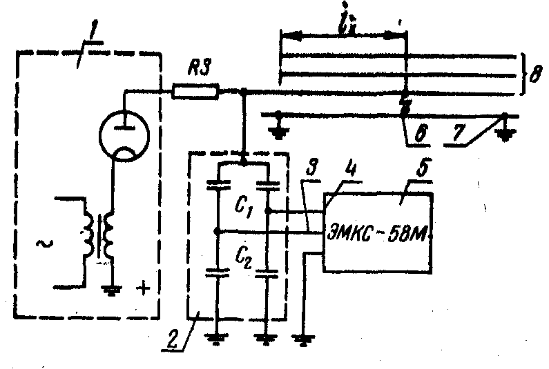
Converting a short circuit between a core and a shell into a short circuit between the cores. The use of the induction method gives good results when finding short circuits between the cores of a three- or four-core cable. Quite often, in the Moscow cable network of Mosenergo, a single-phase short circuit of a 6...10 kV cable can be converted into an intercore one by using the burning technique proposed by V. M. Bronstein. The combustion circuit diagram is shown in Fig. 3.13, b.
During the period of burning the insulation of conductor A using a VG rectifier, providing a voltage of 5...10 kV and a current of 1...3 A,
to this core through the arrester R p connect a pulse installation consisting of a capacitance of two undamaged wires IN And WITH relative to the shell, ballast capacitor Cb (optional) and high voltage rectifier UVV (at full test voltage).
The container is periodically charged to the breakdown voltage of the spark gap R p, which is set equal to 20...25 kV, and the discharge current pulse destroys the conductive bridge formed under the influence of the current from the VG rectifier in the discharge channel. The periodic creation and destruction of a conductive bridge increases the amount of insulation destruction. The voltage on other cable conductors in the transient mode increases the probability of a breakdown transferring from these conductors to the damaged one. If a breakdown occurs, it is impossible to raise the voltage from the air-blast installation and stop the arrester from triggering. It is not possible to convert a single-phase fault into a phase-to-phase fault in all cases.
Burning insulation for weapons of mass destruction using the acoustic method. To use the acoustic method of finding the MF of the core-sheath type, it is necessary to limit the burning current. When currents through the MF exceed several amperes, metallic soldering of the core to the sheath is possible, which precludes the use of the acoustic method. Destruction of a metal junction, as noted above, is not always possible. Therefore, when using the acoustic OMP method, the last stages should not be burned. On the other hand, it is advisable to limit ourselves only to the first stage of burning, since with an increase in the volume of insulation destruction, the part of the discharge energy that creates the acoustic effect increases.
« Floating breakouts. If repeated breakdowns for tens of minutes do not lead to a decrease in the breakdown voltage, then we can conclude that the breakdown occurs in coupling(similar phenomena occur much less frequently in end couplings). First, you need to make sure by visual inspection that there is no damage to the end groove (coupling) at the end of the cable line opposite the installation connection point. After this, the burning should be stopped and the MF should be determined by a combination of vibrational and acoustic discharges.
3.5. Mobile burning units
Currently, installations used in cable networks for weapons of mass destruction are mounted on the chassis of minibuses or regular buses. The main volume of installations is occupied by devices for burning through defective insulation and creating a spark discharge using the acoustic method of OMP.
In these same mobile installations There are devices for non-automatic location, devices using the oscillatory discharge method, induction cable detectors and universal receivers (for induction and acoustic search), devices for the contact method. The units are equipped special drums for connection to the cores of the cable being measured, the ground loop, or a 380 or 220 V supply network. There are also switching and control equipment and measuring instruments control of testing and burning modes.
In mobile installations, safety conditions are ensured by means of interlocking contacts, guards and other means. The vast majority of burning devices provide burning with rectified current. In this case, several stages of voltage and current are necessarily used. At the last stages, i.e. low voltage stages, alternating current (non-resonant burning) of industrial or high frequency (about 1000 Hz) is sometimes used.
Parallel operation of two combustion stages is widely used, when the transition to the next stage is carried out automatically.
We present data from a number of combustion installations. The installation for burning insulation of cables type VT5000 from Seba dynatronic (Germany) has six stages of burning on rectified current
|
Voltage, kV |
||||||

Rice. 3.14. Scheme of parallel operation of two combustion installations:
1 - switch; 2 - diode column; 3 - installation of HPG70;
4 - installation of VT5000
The output power at each stage is about 7 kVA. Installations VT5000 and HPG70 at 70 kV and a current of 0.05 A can be used in parallel according to the circuit shown in Fig. 3.14. Switch 1 disabled. LED post 2 designed for full voltage (70 kV) installation 3 and for the maximum current (110 A) of the installation 4 . This pole ensures parallel operation of both installations. In the event of a breakdown from a high-voltage installation, the arc can be automatically picked up by an installation with a high current. The VT5000 installation has six high-speed electromagnetic switches for combustion stages. In a stable burning mode from the VT5000 installation, the switch turns on.
The company Baltou (Belgium) produces a burning installation of the EDC6000 type. The installation has four stages of combustion at rectified voltages of 24, 12, 6, 3 kV and one stage of combustion at AC voltage 500 V. Continuous burning power is 6 kW at direct current at each stage and 4.5 kVA at alternating current. The installation is powered from a 220 ± 22 V network. The main element of the installation is a transformer with a magnetic shunt device, which ensures stabilization of the output current at all stages of combustion. The transformer has nine secondary windings: eight identical ones to power the bridge rectifier (3 kV;
0.25 A) and one (500 V; 9 A) used for burning on alternating current. The output circuits of the rectifiers are connected in series, mixed and parallel using a switch, providing output voltage settings of 24, 12, 6 and 3 kV.
The power of combustion installations at rectified voltage (which changes little when moving from one stage to another) for cable lines with voltages up to 15 kV, used in Russia, England and the USA, is 10 kVA, in Germany and Belgium 5...7 kVA. Operating experience and analysis of installation parameters shows that optimal value power - 6...8 kVA. In this case, the above relationships between the efficiency and the resistance of the conductive bridge in the MP should be taken into account as much as possible.
If the cable line is damaged, this is fraught with economic losses during transmissions electric current, a short circuit may occur, which will lead to breakdown of powered devices or substations. In case of integrity violation insulating material There may be a risk of electric shock.
Searching for damage to cable lines
Damage to the line can cause a disconnection from the power supply of residential buildings, business facilities, management and control systems of workshops and enterprises, Vehicle. Finding violations in the cable line is of primary importance.
What are the types of damage?
Underground and above-ground electrical transmission lines can be damaged for many reasons. The most common situations are:
- Short circuit of one or more wires to ground;
- Closing several cores simultaneously to each other;
- Violation of the integrity of the cores and grounding them as if they were torn;
- The break lived without grounding;
- The occurrence of short circuits even with a slight increase in voltage (floating breakdown), which disappear when the voltage normalizes;
- Violation of the integrity of the insulating material.
To establish the true type of power transmission disruption, use special device- megohmmeter.

Megaohmmeter
The suspected damaged cable is disconnected from the power sources and the working device. The following indicators are measured at both ends of the wire:
- Phase insulation;
- Linear insulation
- There are no violations of the integrity of the conductors conducting electric current.
Stages of identifying locations of cable line damage
Finding problematic areas in a cable involves three main steps, thanks to which the non-working section can be quickly eliminated:
The first stage is carried out using special equipment. For these purposes, transformers, kenotronomes, or devices capable of generating high frequencies are used. When burning for 20 - 30 seconds, the resistance indicator drops significantly. If there is moisture in the conductor, then the necessary burning procedure takes much longer and the maximum resistance that can be achieved is 2-3 thousand Ohms.

AIP-70 installation for burning cables
This process takes much longer in the couplings, and the resistance indicators can change in waves, either increasing or falling back. The burning procedure is carried out until a linear decrease in resistance is observed.
The difficulty in determining the location of cable damage is that the length of the cable line can reach several tens of kilometers. Therefore, at the second stage it is necessary to determine the damage zone. To cope with the task, effective techniques are used:
- Method for measuring conductor capacitance;
- Probing pulse technique;
- Creating a loop between the cores;
- Creation of an oscillatory discharge in a conductor.
The choice of technique depends on the expected type of damage.
Capacitive method
Based on the conductor's capacitance, the length from the free end of the conductor to the core break zone is calculated.
Scheme for determining damage using the capacitive method
Using variable and D.C. measure the capacitance of the core that is damaged. The distance is measured based on the fact that the capacitance of a conductor directly depends on its length.
с1/lx = c2/l – lx,
where c1 and c2 are the cable capacitance at both ends, l is the length of the conductor under study, lх is the required distance to the place of the supposed break.
From the presented formula it is not difficult to determine the length of the cable to the break zone, which is equal to:
lx = l * c1/(c1 + c2).
Pulse method
The technique is applicable in almost all cases of conductor damage, with the exception of floating breakdowns, the cause of which is high humidity. Since in such cases the resistance in the conductor is over 150 Ohms, which is unacceptable for the pulse method. It is based on applying, using alternating current, a probe pulse to the damaged area and capturing the response signal.

Time sweep of probing reflected signals using the pulse method for determining damage locations: 1, 2, ..., m – single processes repeated with a frequency of 500 - 1000 Hz.
This procedure is carried out using special equipment. Since the pulse transmission speed is constant and amounts to 160 meters per microsecond, it is easy to calculate the distance to the damage zone.
The cable is checked using an IKL-5 or IKL-4 device.
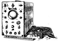
IKL-5 device
The scanner screen displays pulses different shapes. Based on the shape, you can roughly determine the type of damage. Also, the pulse method makes it possible to find the place where a violation occurred in the transmission of electric current. This method works well if one or more wires are broken, but a bad result is obtained if there is a short circuit.
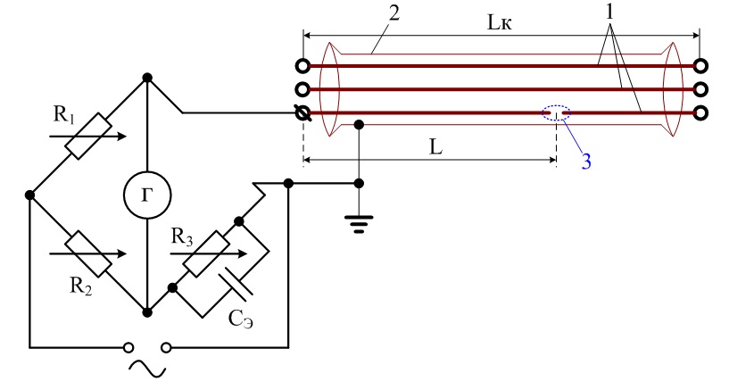
Loop method
This method uses a special AC bridge to measure changes in resistance. Creating a loop is possible if there is at least one working wire in the cable. If a situation arises where all the cores are broken, you should use the cable cores, which are located in parallel. When a broken core is connected to a working one, a loop is formed on one side of the conductor. A bridge is connected to the opposite side of the cores, which can adjust the resistance.

Scheme for determining cable damage using the loop method
Finding damage to the power cable using this technique has a number of disadvantages, namely:
- Long preparation and measurement time;
- The measurements obtained are not entirely accurate.
- Short circuits are required.
For these reasons, the method is used extremely rarely.
Oscillatory DISCHARGE method
The method is used if the damage was caused by a floating breakdown. The method involves the use of a kenotron installation, from which voltage is supplied through the damaged core. If a breakdown occurs in the cable during operation, a discharge with a stable oscillation frequency is necessarily formed there.
Considering the fact that an electromagnetic wave has constant speed, then you can easily determine the location of the damage on the line. This can be done by comparing the frequency of oscillations and speed.
Scheme for determining damage using the oscillatory discharge method
Having established the area of damage, an operator is sent to the suspected area to find the point of damage to the power cable. To do this, they use completely different methods, such as:
- Acoustic capture of spark discharge;
- Induction method;
- Rotating frame method.
Acoustic method
This variant of damage detection is used for underground lines. In this case, the operator needs to create a spark discharge in order to prevent the cable from malfunctioning in the ground. The method works if at the point of damage it is possible to create a resistance of more than 40 ohms. The strength of the sound wave that a spark discharge can create depends on the depth at which the cable is placed, as well as on the structure of the soil.
Scheme for determining damage using the acoustic method
A kenotron is used as a device capable of generating the necessary impulse, in the circuit of which it is necessary to additionally include a ball gap and high voltage capacitor. An electromagnetic sensor or a piezo sensor is used as an acoustic receiver. Additionally, sound wave amplifiers are used.
Induction method
This is a universal method for searching for all possible types of cable faults; in addition, it allows you to determine the damaged cable line and the depth at which it lies underground. Used to detect couplings connecting cables.

Scheme for determining cable damage using induction method
The basis of this method is the ability to detect changes in the electromagnetic field that occur when current moves along an electric line. To do this, a current is passed, which has a frequency of 850 - 1250 Hz. The current strength can be within a few fractions of an ampere up to 25 A.
Knowing how changes in the electromagnetic field under study occur, it will not be difficult to find the location where the integrity of the cable has been compromised. In order to accurately determine the location, you can use cable burning and converting a single-phase circuit into a two- or three-phase one.
In this case, you need to create a core-core circuit. The advantage of such a circuit is that the current is directed in opposite directions (one core forward, the other wire backward). Thus, the field concentration increases significantly and it is much easier to find the location of the damage.
Frame method

Scheme for determining cable damage using the frame method
This good way to find non-working areas on the surface of a power line. The principle of operation is very similar to the induction method. The generator is connected to two wires or to one wire and sheath. Then a frame is placed on the damaged cable, which rotates around an axis.
Two signals should clearly appear at the location of the violation - minimum and maximum. Beyond the intended zone, the signal will not fluctuate without producing peaks (monotonic signal).
(VPU-60 + MPU-3 "Phoenix")
Company "ANGSTREM"supplies three types :
1) Installations for testing and burning high-voltage cables with a maximum voltage of 60–70 kV, used as auxiliary equipment on initial stages burning.
2) Burning installations with a maximum voltage of 20–25 kV, with several high-voltage and one low-voltage sources.
3) Afterburning installations designed to destroy the metal bridge between the core and the shell high currents(300 A) in case single-phase fault on the core.
When choosing a particular model, it is necessary to take into account both production tasks and the characteristics of existing equipment and its compatibility with the purchased one.
An example of compatibility of ANGSTREM equipment for burning

Main technical characteristics of burning installations of the ANGSTREM company
| Name of equipment | Maximum output voltage, kV | Maximum output current, A | Number of steps | Characteristics of stages, kV |
| 24 | 40 | 4 | 25; 5; 1; 0,3 | |
Important parameters of burning installations
Consists of several high-voltage sources and one low-voltage one. The maximum current and voltage values of each source are called stages, their number can vary from four to six. During the burning process, as the breakdown voltage decreases, the transition to the next burning stage occurs. As soon as the installation parameters make it possible to switch on a more powerful stage for parallel operation (or separately), it is put into operation. A more powerful stage means a unit with lower internal resistance and higher current. Possibility of continuous burning
Old-style burning installations used manual switching of stages by the operator, which often led to interruption of the arc, increased the burning time and created the possibility of “swimming” breakdowns. supplied automatic systems switching stages of burning, eliminating arc rupture at the point of burning, which significantly reduces the time spent on preparatory work For . Such burning is often called “stepless”, which should not mislead specialists: this concept does not at all mean the absence of several power units (stages) - simply switching between them is carried out automatically, without operator participation. To generate high voltage, the design of burning installations uses either oil transformers or “dry” transformers. The issue of automatic switching of stages without arc rupture has been resolved in both types of devices, however, there is an opinion that only dry transformers can provide continuous burning in any conditions. This phenomenon is associated with different energy consumption of two types of transformers in short circuit. Oil transformers have significantly higher power consumption in short circuit mode, so keeping them turned on simultaneously during the entire burning process is ineffective; therefore, when the voltage drops, the source with the oil transformer, which generates a higher voltage, is turned off. Very often, switching to a more powerful burning stage first leads to “swimming,” i.e. to increase the breakdown voltage, in this case you should return to the previous stage of a higher voltage, and then, after reducing the breakdown voltage, move on to the next stage. Enterprise burning installations "ANGSTREM"have the ability to connect , which can start burning from 60–70 kV. This significantly expands the possibilities when performing work on high-voltage cable lines. are used not only permanently, but also as part of mobile electrical laboratories, where the possibility of high-voltage burning is always realized. Operator control of burning currentAn uncontrolled increase in the burning current when the voltage drops leads to damage and failure of adjacent cables, which is especially important when burning in cable channels. IN implemented the ability to automatically or manual installation maximum permissible current, this is a plus that ensures impeccable quality of work of specialists at the work site. Energy consumption, ability to fully operate from an autonomous power source of limited powerMost of cable electrical laboratories, equipped , is mounted on the basis of a GAZelle-type vehicle, on board of which it is not possible to place a power plant with a capacity of more than 6 kVA. Burning Installation Ability"ANGSTREM"operating from a 6 kVA power plant while maintaining sufficient power is functional advantage compared to more power-hungry devices. Burning unit powerPower is one of important characteristics, affecting the burning time and its efficiency. Also more have proven themselves well in conditions where the cables are very frozen and require “drying”. Operating time without overheatingOn complex and inconvenient damage, burning can last several hours. If the device overheats, the process must be interrupted, which can lead to re-sinking of the damaged area. The longer the continuous operating time, all the better. Manufacturing company specialists"ANGSTREM"will always help you with the choice of quality equipment! The article was prepared by specialists from the innovation department © ANGSTREM LLC print version Do you want to receive useful teaching materials? |

+ Acoustic or impact method
Single bridge P333
How electricians look for cable damage
Given the similarity of principles for searching for damage in power cables To find damage, it is more convenient to use other techniques and methods. It is worth noting that in many ways it is easier for electricians to look for holes in their cables, because many “puzzles” typical for finding damage to communication cables do not need to be solved here. For example, cable electricians practically do not use bridge measurement circuits and the contact search method (pins), and after a good burn, the reflectometer does not show " coffee grounds"This is due to the fact that high-voltage power cables can withstand a voltage of about 30 kV and a current of hundreds of Amperes, and accordingly can be used burning and impact methods, described below.
To search for damage and test cables and equipment, electricians do not have enough portable instruments and use an entire mobile laboratory based on a vehicle. Typically, in the Russian version, such a car has the inscription LVI on the body, which stands for high-voltage testing laboratory. At the same time, the laboratory equipment mainly consists of installations rigidly fixed in the body of a car. Considering that the LVI circuit uses high voltages and currents, some of the equipment performs protective functions.
High-voltage compartment of the high-voltage testing laboratory
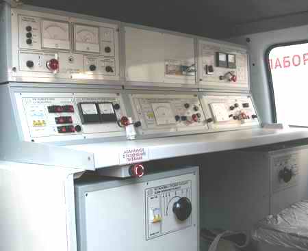
Control panel of the high-voltage testing laboratory
The work of the LVI begins with large quantity number of protective measures. The jokes described in the joke “the most contact search method” are deadly dangerous here. Working with electricians, you begin to understand the meaning of many points from the PUE.
High voltage cable testing
It is curious that often the search for damage begins even without checking the cable with a megger. Start by applying test voltage to the cable. Such a beginning does not correspond to the order of work described in the methods, but is largely justified. The insulation of a “fired” cable can be more than 10 megohms, which, in general, corresponds to the norm and everything is decided by testing the cable with increased voltage.
The voltage is gradually raised to 30-50 kV. As a rule, a breakdown occurs in a damaged cable and the protection of the high-voltage test unit is triggered. The laboratory is switched to another mode - burn mode.
Burning a high-voltage electrical cable
The burning installation is connected. In the photo of the control panel, it is a large cubic block at the bottom left. The installation supplies high voltage to the cable, but without disconnecting in the event of a breakdown. The burning installation has a voltage switch, and the operator can change the current-voltage ratio in the power of the installation. They start with a high voltage and when a stable breakdown occurs, the voltage is reduced in favor of the current, achieving complete fusion of the cable core at the point of damage.
The chemistry and physics of this process lies in the formation of a dense carbon crust at the site of the cable breakdown. Using a similar method, it is achieved that the resistance between the damaged core and the “ground” is reduced to 1-5 Ohms. If the cable does not lie in the ground, but is laid along an overpass, then the search for damage at this stage can be completed. When the cable is burned at the point of damage, it begins to smoke and crack, and the damage is easily found by external inspection.
Measuring high voltage cables with a line discontinuity meter
After successful burning, measuring the line with a reflectometer does not cause difficulties in determining the distance to the damage. The location of the damage is defined as a dense “short” one and is displayed very clearly on the reflectogram. Shortening factor on a high-voltage cable set regardless of the cable brand in 1,87 .
Microphone for
acoustic
search method
damage
By the way, the standard equipment of the LVI includes a reflectometer or line heterogeneity meter. In Soviet times, the package included the painfully familiar P5-10 line heterogeneity meters, and now it is a RI-10M pulse reflectometer.
Acoustic method of damage detection
To search for damage to a cable laid in the ground, another unit is used - a high-voltage pulse generator - GVI (in the photo of the control panel below on the right). In GVI, voltage is supplied to the cable by a sequence of short pulses with quite high power (energy storage by a capacitor is used). All the pulse energy is released at the site of insulation damage, creating a loud dry click (blow). The clicks are so loud that their sound can sometimes be heard even through 70 cm of soil, like soft pops.
Together with the GVI block, another method called acoustic is used. Its essence is to listen to the ground with a special microphone (also sometimes included in the LVI package as part of a search device). As already noted, sometimes breakdown clicks during GVI operation can be heard without any equipment, but the route does not always pass in quiet places and the cable does not always lie at a depth of 60-70 cm. For such cases, the acoustic method is used, that is, listening to the ground with a microphone .
To determine the route and location of damage electric cable The induction method is also used. The essence of the method is described on the page Searching for a cable route with a cable detector. In relation to high-voltage cables, the contact search method (pins) is not used. As a rule, the cable is burned to such an extent that damage is easily localized by one antenna. At the site of damage, the signal is not detected (does not fade) and is heard very clearly; the search is carried out on a vertical coil (to a minimum).
Unfortunately, using such technologies for communication cables is risky. Often, applying high voltage, for example, to a PRPPM can “burn out” a fault (Searching for faults using the phase voltage burning method (220 Volts)) and reduce the fault resistance to several kOhms, and there are often cases when long-term use the GIS-UMGIS ligament reduced the damage resistance. But such methods should be used very carefully for two reasons.
IN last years Non-burning methods for searching for damage to energy cables have become quite widespread in Russia. This is especially true for the pulse-arc method, also known as Arc Reflection. Still, the possibilities for using such methods in the Russian power grid remain limited. This is due to the fact that most of the cable lines remain unrouted, and on such cables, no-burning methods and acoustic search alone will not do. Therefore, the most popular scheme for searching for damage on energy cables in Russia remains and will remain in the coming years the scheme “burning - pulse reflectometry - induction search - acoustic confirmation”.
Fig 1. MPU-3 "Phoenix"
The key to effective work using this scheme is good burning. On the one hand, it must ensure the appearance of a reliable metal bridge at the site of damage, which requires a lot of power. On the other hand, “pumping” high power into the cable during the burning process should not lead to the cable failing in other places.
The current generation of burning installations used in the Russian power grid industry was largely formed under the influence of the small-sized burning device MPU-3 “Phoenix”, which appeared back in 2000. Exactly technical solutions, successfully implemented for the first time in this device, set the requirements for today’s “burners”.
Firstly, this is continuous burning over the entire operating voltage range (for Phoenix it is from 20 kV to 0). The previous generation of burning installations used manual switching of stages by the operator, which led to interruption of the arc, increased the burning time and created the possibility of “swimming” breakdowns. In Phoenix, three sources (20 kV, 5 kV and 600/300 V) are switched on simultaneously through a diode line and do not turn off while the burning process is in progress. Thanks to this, the arc is not interrupted either when the voltage drops or when it increases (“swimming” of the breakdown). This solution turned out to be possible due to the fact that the power transistors, on the basis of which current/voltage conversions are carried out in Phoenix, have almost zero energy consumption in short-circuit mode. Oil transformers - the basis of most other burning devices - have significantly higher power consumption in short circuit mode, and it is expensive to keep them all turned on throughout the entire burning process. Although the issue of switching stages without interrupting the arc in such devices has been resolved, when the voltage increases and the breakdown “floats”, a higher voltage source may already turn off, and then the arc will be interrupted. To this day, Phoenix has no equal when working on “floating” breakouts.
Secondly, it is synchronization of work with high-voltage burning devices and ensuring continuous burning from voltages of 45 - 60 kV to 0. “Phoenix” is connected through a diode line to AID-60P “Vulcan-M”, which can start burning from 60 kV. When the voltage drops to 20 kV, Phoenix picks up the process without interrupting the arc. Today, all serious manufacturers of burning equipment use similar solutions.
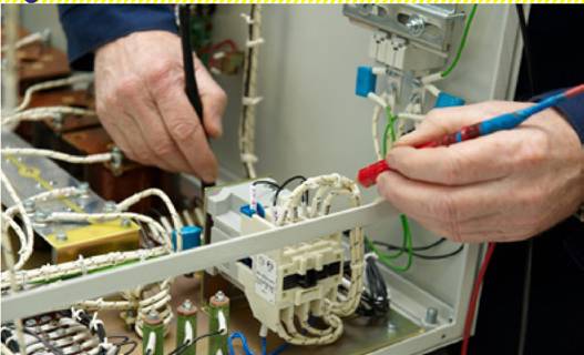
Fig. 2. Installation of MPU-3 "Phoenix" at the assembly stage.
Thirdly, this is operator control of the burning current. This requirement is especially important when burning in cable channels. An uncontrolled increase in the burning current when the voltage drops in such situations often leads to damage and failure of adjacent cables. This is impossible in Phoenix. Each of the power modules in it works as a current source and produces, respectively, no more than 150 mA, 1.2 A and 20 A. Moreover, a version of the device is available with manual limitation of the maximum burning current: the operator sets the maximum permissible current, and, no matter what happens at the damage site, the burning current will not rise above the set value. The issue of limiting and controlling the burning current has not yet been resolved by all manufacturers of burning equipment. In some installations, burning cables in cable ducts is simply dangerous!
Fourthly, this is an effective energy release only at the site of damage. During the burning process, the insulation should not be damaged in other places. The damage site must be burned in such a way that for repair it is enough to install a coupling, and not a cable insert with two couplings. It is this problem that Phoenix solves very effectively: 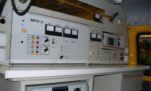
Fig. 3. MPU-3 “Phoenix” installation, built into a mobile electrical laboratory
Even 380 V cables with vinyl insulation do not shed their sheath for meters around the point of damage, but have a clearly localized hole.
Fifthly, a modern burning device must fully operate from an autonomous power source of limited power. Most electrical laboratories today are mounted on the chassis of the GAZelle or its analogues, and sometimes the Sobol. It is simply physically impossible to place a full set of equipment and a power plant with a capacity of more than 6 (rarely 8) kW in such a chassis. To ensure burning from such power sources, developers are creating burning devices low power. You have to pay a high price for this - burning time and its efficiency. Phoenix's own energy consumption is very low, and operation from a 6 kW power plant allows for full combustion even in the most difficult modes.
Sixthly, it works for a long time without overheating. On complex and inconvenient damage, burning can last several hours. High internal energy consumption of the device leads to the device overheating, the process has to be interrupted, and the damaged area “floats” again. Such situations are especially typical when burning occurs in the coupling. Due to its low internal energy consumption, Phoenix is capable of operating continuously for more than an hour without additional ventilation, even in the hot southern summer, and in the winter near Moscow it operates for an unlimited time. Moreover, additional ventilation of the device significantly increases its capabilities when working in hot conditions.
Finally, seventhly, the burning device must be such that it can be used both as a portable autonomous device, and as part of instrument systems mounted on a chassis, and as part of factory-made electrical laboratories. As mentioned above, “Phoenix” is developed on the basis of power transistors, and all conversions in it are carried out at a frequency of 20 kHz. This made it possible not to use oils and to create a compact device weighing 55 kg, at the sight of which the military usually exclaim: “So two soldiers can carry it in their arms!” Despite the fact that “Phoenix” has been in operation for the second decade, in terms of compactness it is still superior to all available “burners”.
 (1 ratings, on average: 5,00 out of 5)

