Manufacturing of cable harnesses. The technical characteristic of the production facility for which this technological process is being developed is the production of harnesses
A set of developed wires and cables connected one to another in some way and, if necessary, equipped with electrical installation elements (tips, connectors, etc.) is called with a tourniquet. According to their purpose, the harnesses are divided into intra-block and inter-block.
In-unit harnesses serve for electrical connection of individual units, blocks and electrical parts inside the device, and interblock are used for electrical connection of various electronic equipment and devices into one system.
The design of the intrablock harness installation is determined by the type of device housing, the requirements for their maintenance and repair. Depending on the placement of units in the housing, such harnesses can be: flat, stationary with detachable connections; flat movable with permanent connections; volumetric movable; volumetric with movable outlets. Permanent connections for intra-block installation are used mainly in electronic equipment intended for harsh operating conditions.
Typical technological process making a harness consists of cutting wires and insulating tubes, laying wires on a template, tying them into a bundle, developing the ends of the wires of the harness and marking them, checking the manufactured harness (continuity), protecting the harness insulating tape and its final control (visual inspection for compliance with the standard and continuity).
Template for laying out harnesses is a rectangular plate made of plastic or plywood, on the surface of which a wiring harness diagram is applied life size and the end and corner studs are secured (Fig. 4.8).
Laying the wire begins by securing it to the corner stud. Then the wire is laid according to the bundle diagram, bending it at the corner studs and securing it to the end stud. The start and end pins have the same number. When all the wires are on the template, they are tied with linen thread.
In harnesses where it is impossible to replace damaged wires, spare wires are provided, the number of which is 8-10% of the total number of wires in the harness, but not less than two. The length and cross-section of the spare wires must be equal to the largest length and cross-section of the wires available in the harness. The length of the harness branches must be sufficient for connection to the nodes and elements of the device circuit without tension; in addition, you should have some extra length (10-12 mm) for re-stripping and soldering each end of the wire.
When preparing harnesses, the following requirements must be met:
two or more parallel insulated wires running in the same direction and more than 80 mm long must be tied into a bundle;
longer wires must be laid at the top of the bundle so that the branch of the bundle comes out from under them. Wires of small sections (0.2 mm2) should be laid in the central part of the bundle;
Depending on the operating conditions, as well as on the insulation of the wires included in the bundle, you need to knit with threads, braid or tapes made of synthetic materials or wrap with electrical insulating tapes or films. You can also use electrically insulating tubes instead of wrapping with tape or perform mechanical and automatic knitting of bundles with threads with tension that does not damage the insulation of the wires;
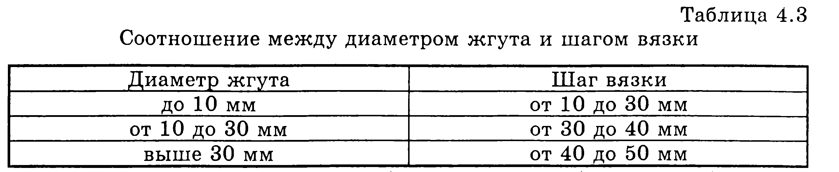
The knitting step of the loops of the tow depends on the diameter of the tow and is selected from Table 4.3.
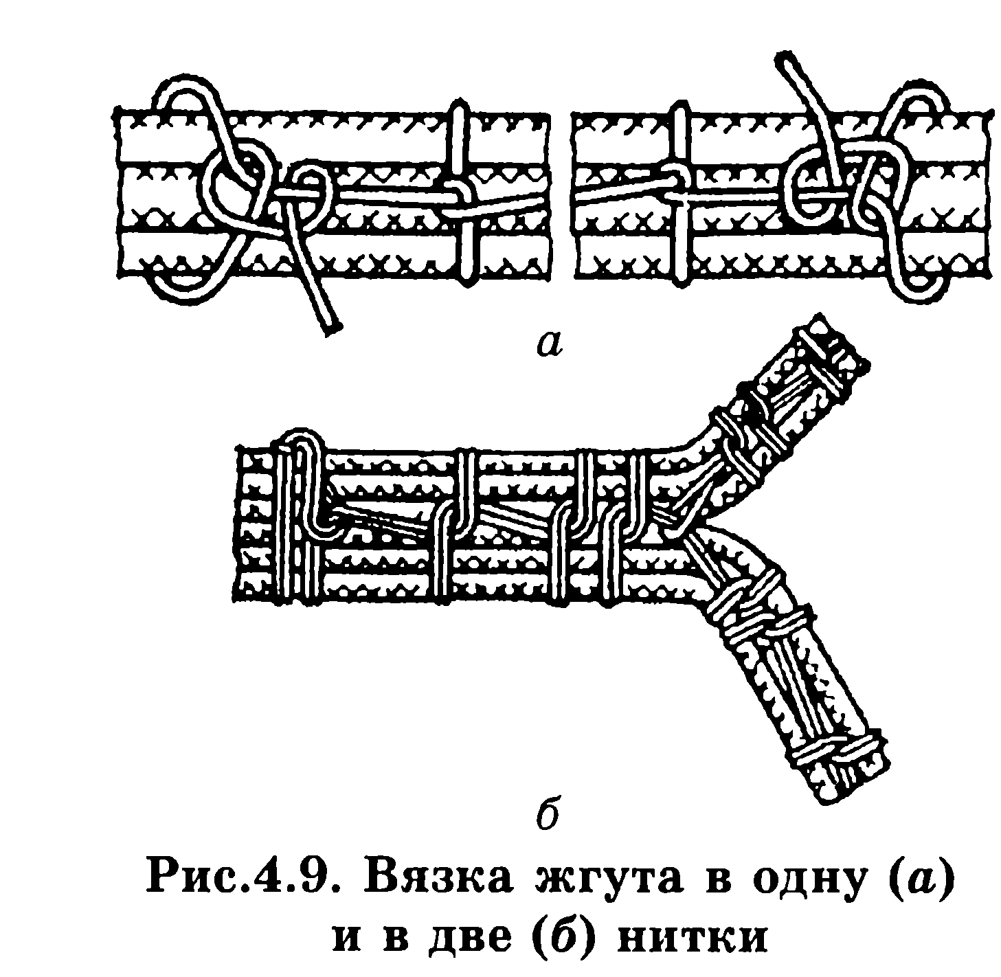
in places where the tourniquet is exposed (before and after it), bandages of 2-3 loops placed side by side should be made. At the beginning and end of the knitting there should also be bandages, which consist of two to five loops and have end knots. A loop must be made before each wire leaving the bundle. An example of knitting and laying with a bandage is shown in Fig. 4.9;
Depending on the number of wires and the diameter of the bundles, knitting should be done in one, two or more threads. Before knitting, it is recommended to rub or soak the threads with ceresin. Knots of linen threads after knitting need to be covered with glue (for example, BF-4) or varnish; The ends of nylon threads need to be melted after knitting.
After tying the wires into a bundle, fix their ends. In this case, all ends of the wires are marked in accordance with the wiring diagram.
Marking of wires, cable products and harnesses during electrical installation, it must be possible to check electrical circuits, finding faults and repairing equipment. The following methods are used for marking: laying wires with different colors; coloring or numbering of polyvinyl chloride tubes used to clamp the ends of the insulation (the tubes are marked on a machine or the numbers are written by hand with marking ink);
putting plastic tags on the wires with symbols of the connection points;
marking the insulation using colored printing foil (for wires with polyvinyl chloride and polyethylene insulation and cables of the RK type);
use of a metal tag (mainly on RK type cables);
use of adhesive marking tape (bandage of 1.5...3 turns per wire or cable).
Markings are applied to both ends of the wire, cable or harness at the points of their connection. The markings of wires, cables and harnesses on labels, tapes and tubes or directly on the wires must correspond to the markings shown in technical documentation. If the tag placed on the wire or cable is not glued, it is tied to the wire (cable) with a knot or loop.
To mark wires with an insulation diameter of up to 1 mm, use colored marking tubes with internal diameter, corresponding to the diameter of the wire.
Marking of wires in the harness is done using tags or tapes made of polymer materials. The length of tags or the width of tapes should be no more than 12 mm.
Then the harness is checked by testing, for which they are connected with a device (indicator) in series to the ends of the wires of the harness with the same numbers.
Inspection of complex bundles is carried out on special semi-automatic stands according to a given program. All information about such control is recorded in a computer.
Fastening of harnesses, wires and cables to the electronic equipment body or its elements is carried out using: staples, tapes, clamps, adhesives, mastics, compounds, threads, ribbons, plastic self-adhesive tapes.
Staples, tapes and clamps must match the shape of the harness and prevent it from moving when fastened.
In order not to damage the insulation of wires when fastening with metal brackets and clamps, it is necessary to place elastic gaskets made of insulating material protruding beyond the edge of the brackets (clamps) by at least 1 mm.
The distance between brackets or clamps when fastening them in linear sections must be selected depending on the diameter of the bundle (wire or cable) in the range from 100 to 300 mm. Identical wires with a cross-section of less than 0.35 mm 2 must be fastened with a distance between the fastening points of no more than 80 mm.
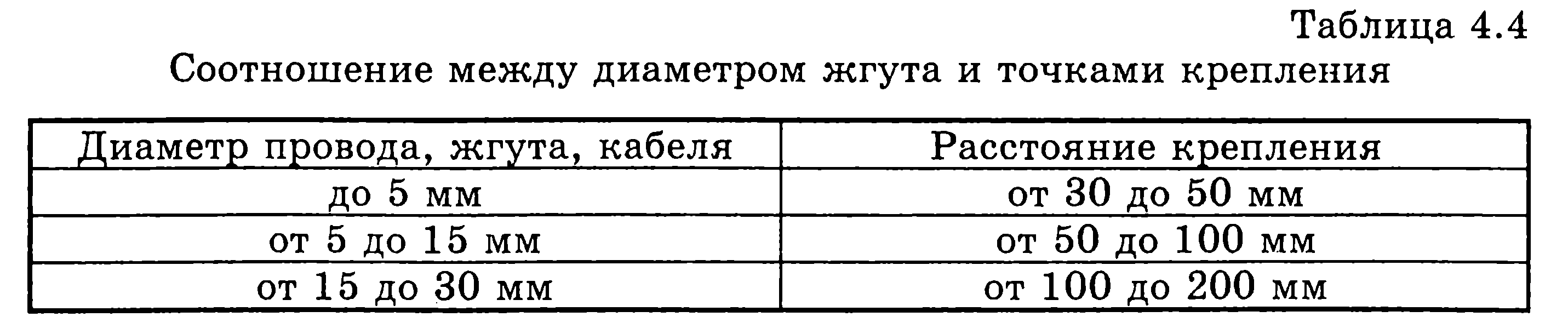
When glue or mastic is used to secure wires, harnesses and cables, the distance between the gluing points should be selected depending on the diameter of the wire (harness or cable) according to Table 4.4
When gluing, harnesses with a diameter greater than 15 mm are secured with threads through a hole in the chassis.
The passage of a harness, wire or cable through a hole in a metal chassis must be done through an insulating sleeve that is installed in the hole.
When moving wires, harnesses and cables from a stationary part of the device to a moving one (for example, from a case to a board or panel, etc.), it is recommended to place them in such a way that the wires are twisted rather than bent when the moving part is removed. In this case, the moving parts of the tourniquet do not need to be tied and the necessary margin in length is left.
Soldering and tinning: purpose, application and physico-chemical basis. Solder, fluxes of their brand and application. Soft soldering technology hard solders, temperature conditions, heat dissipation. Group soldering methods. Equipment and tools: purpose, design and working methods. Methods for soldering wires of various brands and sections. Ultrasonic soldering. Laser soldering. Requirements for soldering connections, quality control. Purpose and application of tinning, quality control. Automation of soldering and tinning processes
Soldering- physical and chemical process of obtaining a compound as a result of the interaction of solid and liquid metal (solder). The layers resulting from this interaction at the boundaries of the seam and the joined surfaces of the parts are called solders. To obtain joints, it is necessary to remove oxide films from the surfaces being joined and create conditions for the interaction of solid and liquid metals. During crystallization of the material that has come into interaction with the material of the parts being soldered, more fusible solder a soldered connection is obtained.
One of the advantages of soldering is the ability to connect many elements that make up the product into a single unit in one step. Soldering, like no other connection method, meets the conditions of mass production. It allows you to connect dissimilar metals, as well as metals with. glass, ceramics, graphite and other non-metallic materials.
Tinning is the process of coating electrical installation elements with solder (electrical electrical terminals, contact pads printed circuit boards, metallized holes, cores of installation wires and cables, etc.) It is necessary to improve the solderability of the connected surfaces of elements during their installation.
To make a high-quality solder connection you need:
7. prepare the surfaces of the parts to be soldered;
8. activate soldered metals and solder;
9. ensure interaction at the “base metal - liquid solder” boundary;
10. create conditions for crystallization of the liquid metal layer of solder.
Surface preparation includes removing contaminants and oxide films from it that interfere with wetting by molten solder. Films are removed mechanically or by chemical means. During mechanical cleaning
a thin surface layer of metal is removed using sandpaper, a wire brush, etc. To increase productivity when processing large surfaces (for example, printed circuit boards), waterjet processing or cleaning with rotating brushes made of synthetic material into which abrasive particles are introduced is used. The roughness of the surface after mechanical cleaning promotes the spreading of flux and solder, since small scratches on the surface are the smallest capillaries.
Chemical treatment(degreasing) the surface of the product is carried out in alkali solutions or organic solvents (acetone, gasoline, alcohol, carbon tetrachloride, freon, alcohol-gasoline and alcohol-freon mixtures) by wiping, lowering into a bath, etc.
Cleaned parts must be immediately sent for tinning and soldering, since the storage time for copper is 3-5 days, for silver - 10-15 days.
Activation of the metals and solder being joined occurs with the help of various fluxes, the creation of a special gas environment or physical and mechanical effects (mechanical vibrations, ultrasonic vibrations, etc.). Activation is necessary, since when metals are heated and solder is melted, their surface layers interact with atmospheric oxygen, which leads to the formation of a new oxide film.
Soldering with fluxes is the most common. The molten flux spreads over the soldered surface and solder, wets them and interacts with them, as a result of which the oxide film is removed. But the use of fluxes can lead to the fact that their residues after soldering, as well as the products of their interaction with oxide films, create slag inclusions in the soldered seam. This reduces the strength of the connection and leads to corrosion. To avoid this, flux residues after soldering are usually washed off (wiped) with organic solvents.
To ensure interaction at the “base metal - liquid solder” boundary, it is necessary to achieve good wetting of the surface of the base metal (electrical electrical terminals, petals, wires, etc.) with molten solder. The strength, corrosion resistance and other properties solder connections. The process of wetting and spreading of solder is influenced by certain technological factors (method of removing the oxide film, brand of flux used, soldering mode, etc.).
Crystallization of the liquid metal layer occurs after removal of the source of thermal energy. The crystallization process has a significant impact on the quality of solder joints.
Solder and fluxes for soldering are designed for performing technological processes of hot tinning and soldering of non-ferrous and ferrous metals and metallic and non-metallic materials metallized by them. They are divided into:
solders for low-temperature soldering with a melting point less than 450 °C;
solder for high-temperature folders with a melting point above 450 °C.
The symbol for solder brands consists of the letters "P" or "Pr" and the following abbreviated names of the main components: tin - O, lead - C, antimony - Su, bismuth - Vi * cadmium or cobalt - K, silver - Cr, copper - M , indium - In, zinc - C, nickel - N, gallium - Gl, germanium - G, titanium - T, gold - Zl, manganese - Mts, boron - B, phosphate - F, brass or lithium - L, iron - F , aluminum - A. Next, the content of the main component is indicated as a percentage of the mass. The letter "P", which appears at the end of the brand with a hyphen, means that the solder has increased purity.
The main brands of solders and their melting temperature (T pl) are shown in Table 4.5.

Fluxes are intended for use in technological processes of soldering and hot tinning to remove the oxide film from soldered surfaces and solder, protect the surface of metals and solder from oxidation during the soldering process, as well as reduce the surface tension of molten solder at the metal-solder-flux interface
The symbol for brands of fluxes consists of the letter "F" (flux) and the abbreviated name of its components: K - rosin, Sp - alcohol, T - triethanolamine, Et - ethyl acetate, C - salicylic acid, B - benzoic acid, Bf - cadmium borofluoride (or zinc), P - polyester resin, D - diethyl amine, SK - semicarboside, G - glycerin, Fs - orthophosphoric acid, C - zinc chloride, A - ammonium chloride, B - water, L - laprol, Kp - catapine, M - maleic acid.
Fluxes are low-temperature (use temperature less than 450 °C) and high-temperature (use temperature above 450 °C). Depending on the corrosive effect on the metal being soldered, they are divided into the following groups: non-corrosive inactive, non-corrosive weakly active, slightly corrosive active, corrosive active, highly corrosive.
To avoid corrosion of the field connection, residues of corrosive and even slightly corrosive fluxes must be removed immediately after soldering. Fluxes are removed with liquids in which they dissolve. For some brands of fluxes this may be organic solvents, for others - water.
The most common brands of fluxes are given in Table 4.6.


In addition to fluxes, protective liquids (for example, ZhZ-1, ZhZ-2, TP-22) are used to protect the surface of molten low-temperature solder from oxidation in tinning and soldering baths. They are a mixture of petroleum oils with organic components.
The quality of solders and soldering fluxes is determined by technological characteristics: spreading coefficient (K p) and wetting time (t CM). Coefficient K p = S p /Sq, where S p is the area occupied by solder; Sq - area of unmelted solder in the initial state; tCM - time during which the mounting element is tinning (should be no more than 3 s).
Soldering technology with soft and hard solders, temperature conditions, heat dissipation. The technological process of soldering consists of the following operations:
preparing the surfaces of connected elements for soldering; fixing the connected elements tightly to one another; applying a dosed amount of flux and solder; heating parts to a given temperature and holding for a certain time; *
cooling of the soldered joint without shifting its parts;
connection cleaning; soldering quality control.
Soft (low-temperature) solders (see Table 4.5) are used for electrical installation of equipment. Therefore, the temperature conditions for their use depend on the permissible temperature for those elements that take part in the installation. Soldering can be done with a soldering iron or in baths of molten solder. When tinning and soldering using molten solder, the required bath temperature increases for each brand of solder according to the formula
tп = tнк + (45...80) °С,
Where tn - solder temperature, tHK - crystallization onset temperature (first digit T pl in table 4.5). The amount of excess (45...80) °C above tHK depends on the mass of the soldered product, immersion time, flux used, limitations on thermal effects in accordance with the technical specifications for electric power products.
To avoid overheating of the soldered ERE, a heat sink is used, which is fixed to the ERE terminals during soldering.
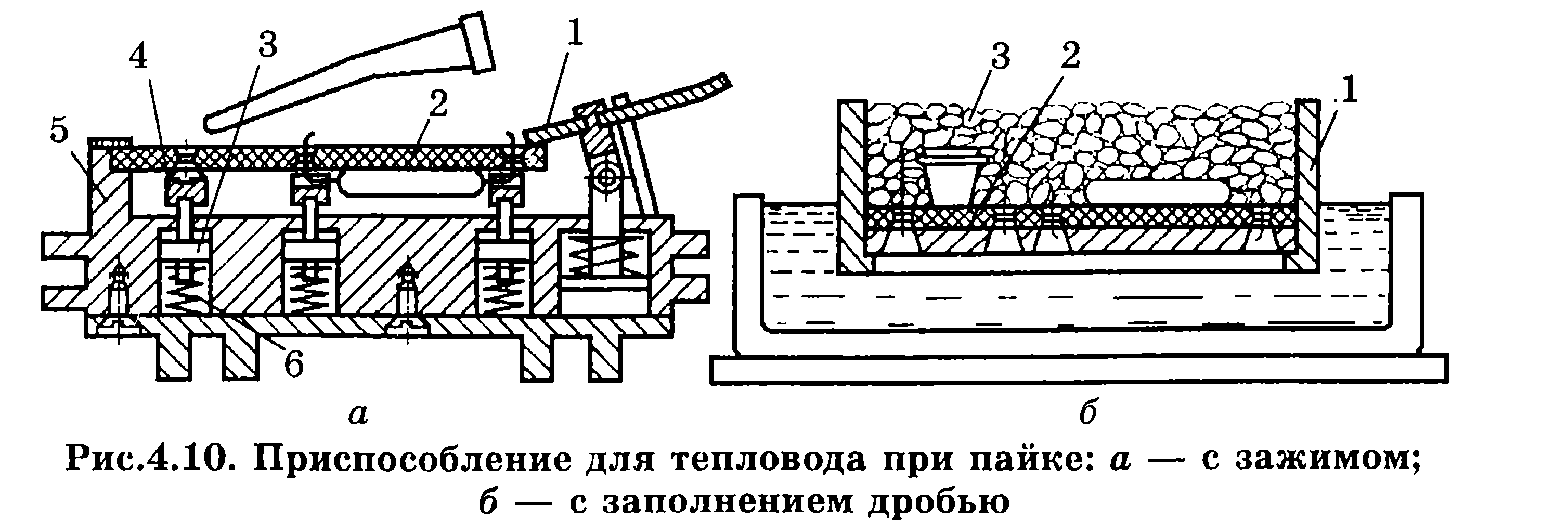
There are other methods of heat removal during individual and group soldering of circuit boards. Circuit board 2 (Fig. 4.10, A) is installed in fixture 5, made by injection molding in the form of a thermal block. Built into the housing are racks 3, pressed by springs 6, which carry support copper sockets 4 on top, which have slots for leads. Mounting board 2 is installed on these heat sink racks so that the leads of the radio elements fit into the slots of the sockets. The board is fixed in the device by turning the clamping bar 1. Thus, during the period of individual soldering, heat is removed by the entire body of the device.
When group soldering of hinged elements on a circuit board, a heat removal method is used, carried out using aluminum wire shot with a diameter of 3 mm (Fig. 4.10, b). Shot 3 is poured into holder 1, into which circuit board 2 is inserted before group soldering by immersion or hydrostatic method. At the end of soldering, the shot is poured out.
Hard (high-temperature) solders are used for structural soldering of mechanical joints in the manufacture of large parts (for example, chassis, housings, etc.). High-temperature soldering of mechanical joints is performed in high-frequency current fields (HFC), in ovens or baths with molten salt.
Induction soldering (HFC). The technological device for induction soldering or soldering with high frequency currents (HFC) is an inductor, which is a coil made of highly conductive tubular material through which coolant is pumped. An HDTV generator is used as soldering equipment. Typically, induction soldering is used to connect elements operating at ultrahigh frequencies (microwaves), for example, microwave waveguides. The quality of the connection increases when the soldering process is carried out in a vacuum or in a protective gas environment (hydrogen, nitrogen or a mixture of both). The big disadvantage of HDTV soldering is the need special devices for each assembly unit.
Soldering in ovens with a controlled atmosphere ensures uniform heating. Heating of soldered materials is carried out in an active gaseous environment. In this case, fluxing may not be used.
Soldering in baths with molten salt is used for assembling large-sized products. The composition of the melt is selected in such a way that it provides desired temperature and had a fluxing effect on the surfaces being joined. Assemblies assembled for soldering (the gap between the soldered parts must be within 0.05...0.1 mm) are preheated in an oven to temperatures 80...100 °C below the melting point of the solder. This is necessary to avoid warping of parts, as well as to maintain the temperature in the bath. After soaking in the melt for 0.5...3 minutes, the part along with the device is removed from the bath and cooled, and then thoroughly washed with water to remove flux residues.
Group soldering methods. Group soldering methods in the production of electronic devices are classified according to the sources of thermal energy, which is the main factor in the formation of solder joints (Fig. 4.11). Soldering of elements with pin terminals, which are placed on printed circuit boards, in continuous production conditions is carried out by two methods: immersion and wave solder.

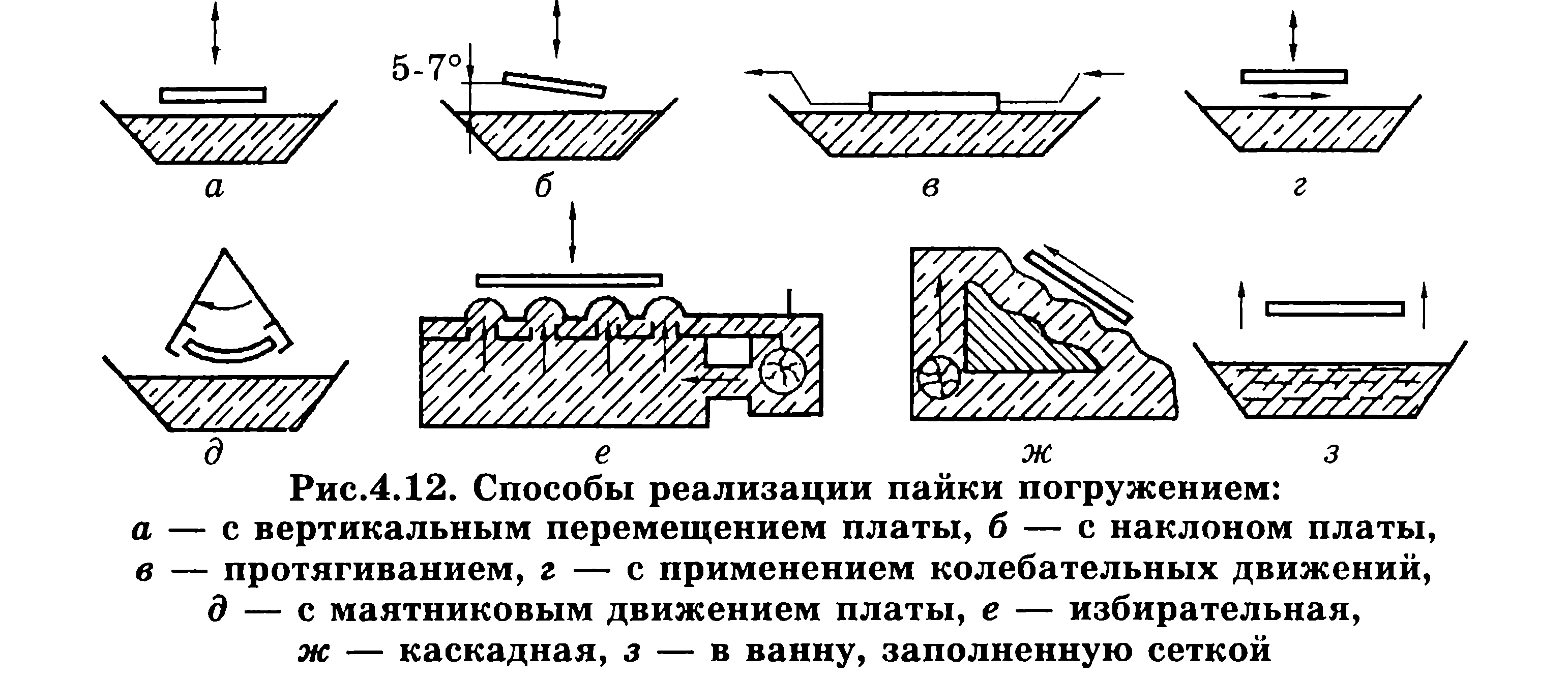
Different variants The implementation of group folder methods is shown in Fig. 4.12. When soldering, the printed circuit board is immersed in molten solder to a depth of (0.4...0.6) for 2...4 s h, Where h - thickness of the board. As a result of the capillary effect, the mounting holes are filled with solder (Fig. 4.12, A). Simultaneous exposure of the entire surface of the board to temperature leads to overheating and can cause increased warping. To reduce the area of action of solder, a special mask (made of paper or fiberglass) is glued to the board on the mounting side, which has holes for contact pads. The remaining flux solvent that gets into the solder evaporates rapidly, which leads to local failures. To reduce the number of unsoldered parts, dip soldering is used with the board tilted (angle 5... 7°) (Fig. 4.12, b) or apply mechanical vibrations to the board with a frequency of 50...200 Hz and an amplitude of 0.5...1 mm (Fig. 4.12, d, d). Good results can be obtained by pulling the board along the solder mirror (Fig. 4.12, V). In this case, the board is installed on the fixture at an angle of 5°, immersed in solder and pulled along its surface. This method creates suitable conditions for removing oxidation products.
Selective soldering(Fig. 4.12, e) provides selective supply of solder to the soldered parts through special dies made of stainless steel. Between the board and the filters there is a layer of heat-resistant rubber. With selective soldering, the temperature of the board and the heating of the electrical components are reduced, and the consumption of solder is reduced, but the cost of manufacturing special dies can be significant.
Wave soldering is the most common group soldering method. In this case, the board moves directly linearly across the crest of the solder wave. Its advantages are high productivity and short interaction time between the solder and the board, which reduces overheating of the electrical element and warping of the dielectric. A type of wave soldering is cascade soldering (Fig. 4.12, g), in which several waves are used.
High quality soldering is ensured by the method of immersing the board in a bath containing a mesh with 0.2x0.2 mm cells, for example, made of nickel (Fig. 4.12, h). When the board touches the grid, the solder is pressed through the cells and, under the action of capillary effect, enters the gap between the leads and the plated holes. When moving back, excess solder is drawn into the capillaries of the mesh, which prevents the occurrence of “icicles.”
Equipment and tools: purpose, design and working methods. Depending on the type of production, soldering is carried out individually using a heated soldering iron or using various group methods.
Soldering with a soldering iron used for electrical installations in single or small-scale production.
Design electric soldering iron shown in Fig. 4.13. Needed temperature regime for individual soldering, it is ensured by the thermophysical characteristics of the soldering iron used: the temperature of the working end of the tip (tip 1 in Fig. 4.13), the stability of this temperature, which is maintained using thermocouple 4, and the power of the heating element 14.
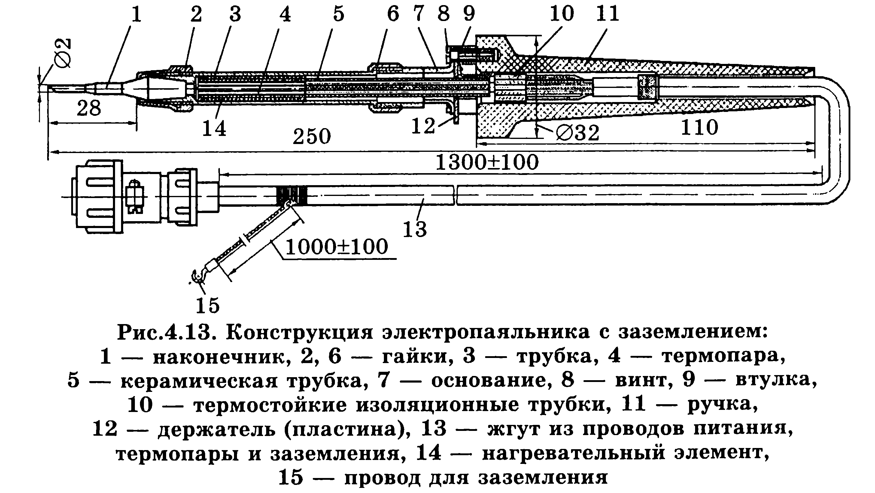
The temperature of the working end of the tip is set 30... 100 °C above the melting temperature of the solder, since during the soldering process the temperature of the soldering iron tip decreases due to heat costs when heating the soldered parts. Recommended power of soldering irons for soldering microcircuits is 4... 18 W, for printed circuit assembly 25...60 W, for soldering wires (harnesses) 50... 100 W.
Soldering iron tips use copper, which is plated with a layer of nickel to increase its wear resistance. Sequence of the soldering process with a soldering iron: flux the elements of the assembly connection using a brush dipped in liquid flux; heat the elements of the installation connection by touching them with a soldering iron tip; insert a rod of solder into the soldering zone; withstand heating until the solder reaches normal spreading and fills all the gaps between the surfaces being connected.
After soldering is completed, do not touch the parts until the solder is completely hardened. The total time for soldering one field connection with a soldering iron is 1...3 s and cannot be more than 5 s.
If soldering and tinning is performed manually, it is necessary to ensure heat removal from electronic components, semiconductor devices, ICs, etc., which are sensitive to its effects (according to the specifications for these elements). Heat sinks in the form of clamps are fixed to the terminals of the soldered elements between the soldering points and the element body. After soldering, the heat sinks are removed no earlier than after 5 s. For reuse heat sinks are changed or cooled.
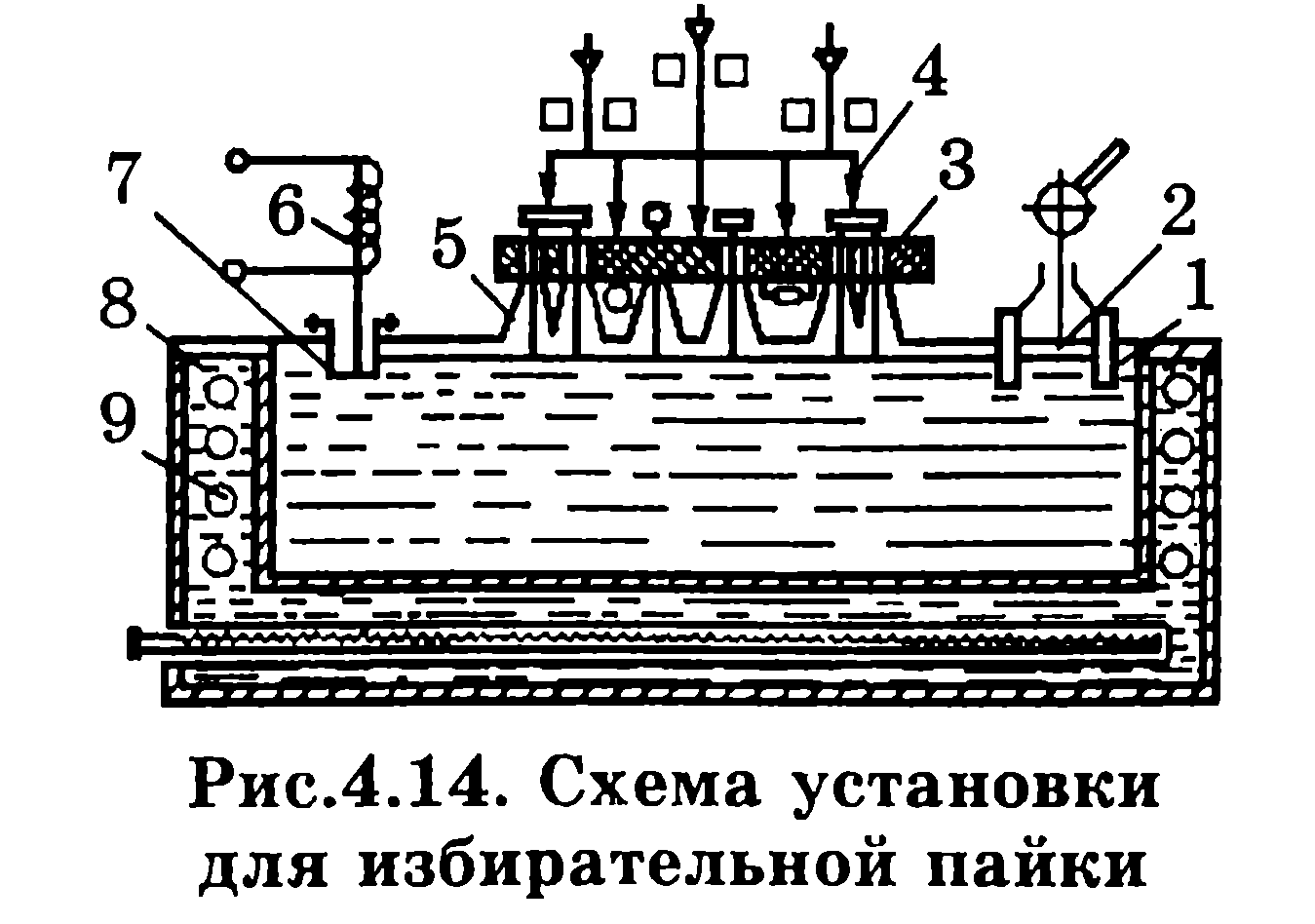
Installation diagram for selective soldering is presented in Fig. 4.14. Board 3 with leads pre-coated with flux is installed on die 5. Each soldering point has its own die, the hole of which must coincide with this place. In this position, the board is secured with a clamp 4. The molten solder 1 is in a volume closed on all sides, and its temperature is maintained by the molten medium of the salt bath 8, heated by electric heating elements 9. Through the bronze diaphragm 7, the vibrator 6 transmits vibrations to the molten solder with a frequency of 100 Hz, which improves the quality of soldering. Solder is fed through dies to the soldering points by lowering piston 2.
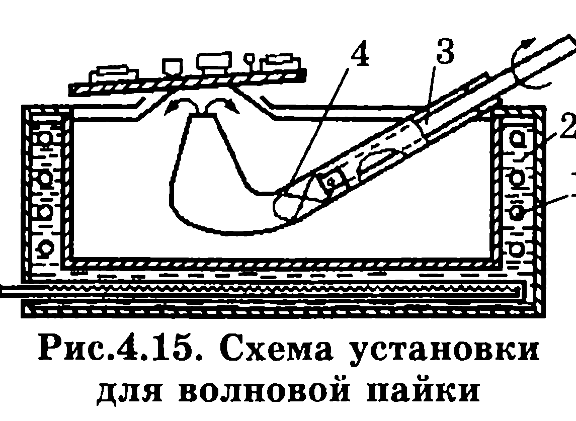
Installation diagram for wave soldering shown in Fig. 4.15. In a bath of molten solder, the temperature of which is maintained by a salt bath 2 with heating elements 1, a pipe with a blade pump 4 is installed, driven by an electric motor using a shaft 3. The height of the wave depends on the rotational speed of the electric motor and is regulated by changing it.
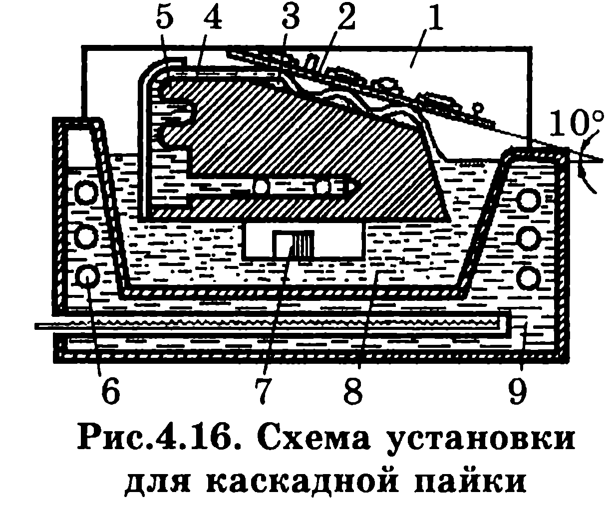
Cascade soldering differs from wave in the presence of several waves (Fig. 4.16) created by thresholds 3 on the inclined surface of the base 5. Molten solder 8 by pump 7 through slot 4 with constant speed enters these thresholds and flows down. The solder is protected from flowing in other directions by the side walls 1. As in the previous schemes, the temperature of the solder is maintained by a salt bath 9 with electric heaters 6.
These types of soldering are most appropriate for large-scale and mass production of boards with one-sided arrangement of hinged elements. They ensure continuous movement of the boards during soldering and local heating.
Methods for soldering wires different brands and sections. After processing, as described above, mounting copper wires and cable cores that do not have a coating must be tinned. After stripping the insulation, individual wire strands must be twisted before servicing. When tinning wires and cables, it is recommended to apply flux at a distance of 0.3 to 2 mm from the insulation. Untinned sections of the core between the insulation and the tinned part of the wire are allowed up to 1 mm. The cross-sections of the current-carrying conductors must correspond to the load current. The total cross-sectional area of wires and ERE terminals connected to the contact should not exceed smallest area contact sections.
When soldering wires and cable cores, the following requirements must be met: connections between wires must be made using electrical contacts. Options for fastening wire cores and ERE terminals to contacts different designs shown in Fig. 4.17:
No more than three wires can be soldered into each soldered contact hole. In this case, each wire must be secured in the hole independently, without twisting it with other wires and ERE terminals. If the mounting hole is too small for soldering, it is necessary to use electrical support contacts; The wire must be attached to the clamping contacts only using cable lugs (no more than two wires for one clamping contact). The clamping contacts must be secured with paint or varnish;
wires of small cross-sections (less than 0.2 mm2) must be installed carefully; laying the wires must be carried out only once so as not to break them;
the drive supply in the form of a loop is placed on the board, but the wire should not hang over its edge; the wire to the soldering point must be brought from below; The connection of installation wires to the contacts must be carried out in such a way that the length of the bare part of the installation wire core from its insulation to the place of soldering is no more than 2 and no less than 0.5 mm (after soldering). When the distance between contacts is less than 5 mm, wire exposure should not exceed 1.5 mm.

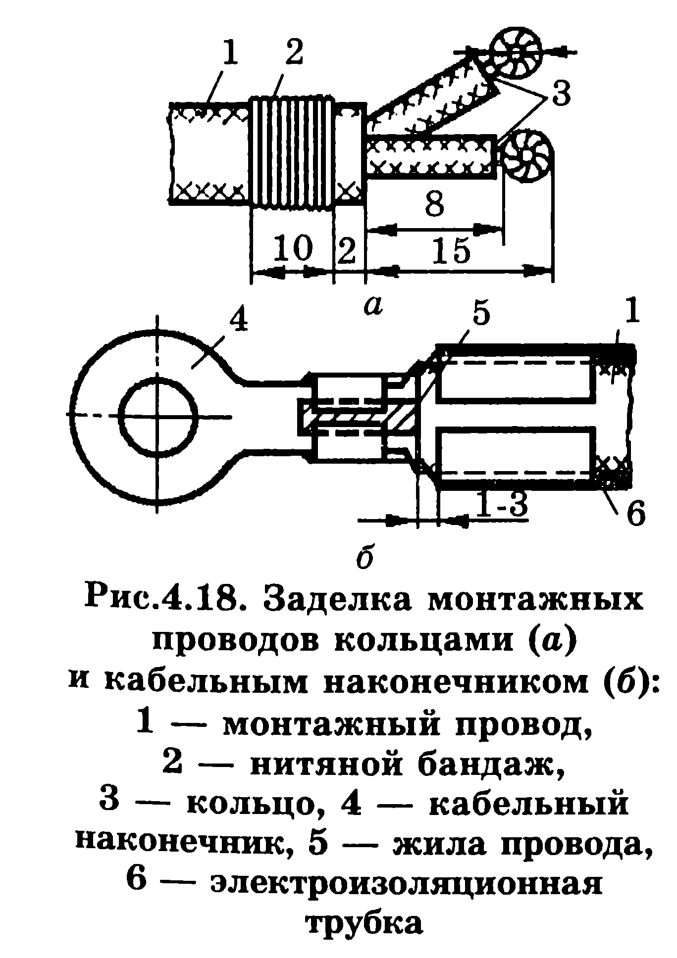
Connection of installation wires to screw terminal blocks is carried out in various ways. In one of them, rings with a diameter larger than the diameter of the screw are made from stripped and tinned wire cores (Fig. 4.18a). In another method, cable lugs with screw holes are attached to the wire cores by soldering, welding or crimping (Fig. 4.18, b).
Laying wires in a cable lug is carried out in the following sequence: an electrical insulating tube with an internal diameter equal to the external diameter of the wire is put on the wire; The wire core, after cutting and tinning, is inserted into the tip; the legs of the tip crimp and solder the wire core from the inside to the legs; crimp the following paws onto the wire insulation; An electrical insulating tube is placed on top of the tip
(Fig. 4.18, b).
Ultrasonic soldering. Ultrasonic vibrations introduced into the solder destroy oxide films on the metal surface, improve its wetting with liquid solder, the flow of solder into the capillary recesses, and promote degassing of the melt, which improves the quality of the soldered joint.
The cavitation that occurs in the solder under the influence of ultrasound contributes to the destruction of oxide films, and acoustic currents carry away particles of oxides and contaminants and remove metal at the sharp edges of the contact. Exposed areas of metal are easily wetted with solder.
Laser soldering. Laser radiation differs from other sources of electromagnetic energy in its very narrow focus. Concentrated heating with focused radiation energy has a number of advantages, the main of which are: non-contact energy supply to products by removing the source from the heating object; the ability to transfer energy through optically transparent shells both in a controlled environment and in a vacuum; heat different materials regardless of their electrical, magnetic and other properties in a wide range of regulation and control of soldering parameters. Depending on the design features and the mass of soldered products, as well as the properties of the materials being connected, use various equipment of different power.
Requirements for solder joints, quality control. TO
Soldered joints have the following requirements:
When fluxing, flux must not be allowed to get inside the ERE and onto the contact parts electrical connections;
the shape of the solder joints should be frame-shaped with concave solder fillets (Fig. 4.19) and without excess solder. It should allow you to visually view through thin layers of solder the contours of the individual electrical elements included in the connection;
the surface of the solder fillets along the entire perimeter of the soldered seam should be concave, continuous, smooth, glossy or light matte, without dark spots and side inclusions.

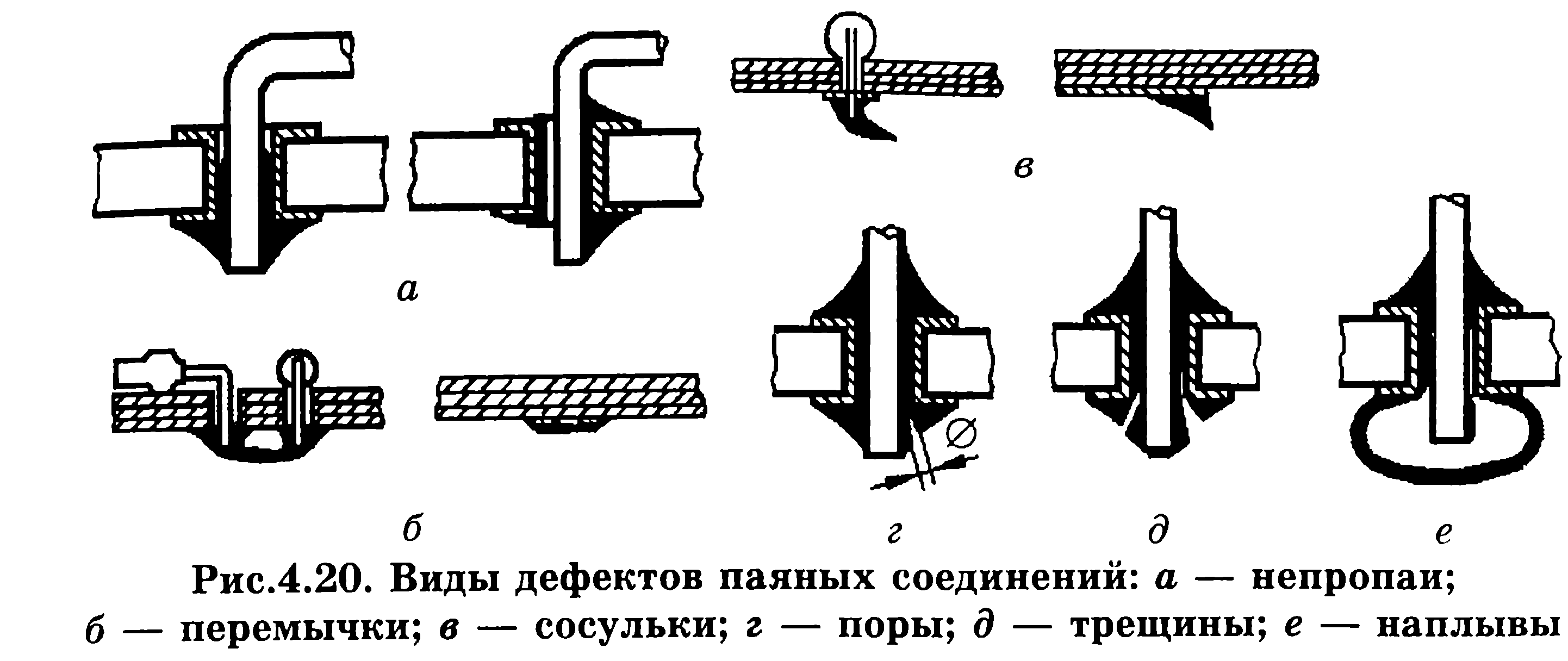
The quality of soldering is checked by external inspection, and, if necessary, using a magnifying glass. A well-executed soldering should be considered one in which the contours of the parts being connected are clearly visible, but all the holes are filled with solder. The soldering must have a glossy surface, without sagging, cracks, or sharp slopes. Possible types of solder joint defects are shown in Fig. 4.20.
The mechanical strength of the soldering is checked with tweezers with polyvinyl chloride tubes placed on its ends (when indicated in the TD). The tension force along the axis of the wire should be no more than 10 N. It is prohibited to bend the wire near the soldering area. After inspection and acceptance, the soldering area is painted with a transparent colored varnish.
Purpose and use of tinning, automation of soldering and tinning processes. The high demands placed on fixed connections of parts and elements during electrical installations carried out by soldering necessitate the hot tinning operation.
Typically, hot tinning of electrical components is carried out only if their solderability is unsatisfactory (the need to control solderability is included in the technical documentation). When tinning, the following requirements must be met:
Tinning of electrical installation elements (electrical electrical terminals, contact pads of printed circuit boards, metallized holes, installation wire cores, etc.) should be performed mainly with the same solders as subsequent soldering. Temperature-sensitive EREs are tinned with solders with a low melting point. Just as with soldering, when tinning such electronic elements it is necessary to use heat sinks;
Application of flux to the surfaces to be tinned during manual tinning should be carried out for the minimum time necessary to ensure wetting of the surface with solder. With mechanized tinning, the entire surface that touches the solder is fluxed;
when tinning, the distance along the length of the ERE lead from the solder mirror to the ERE body must be at least 1 mm (or in accordance with the specifications for the ERE);
when tinning electrical electronics terminals manually by immersion in solder or with electric soldering irons, the duration of the process should not exceed the time specified in the technical specifications for electrical electronics. When there is no such limitation, the duration of tinning is taken to be no more than 5 s.
Page 61 of 71
Layout and knitting of bundles can be done using templates.
The template must be made in accordance with the drawing for the harness, and if there is no drawing, according to the wiring diagram. The wire cutting on the template is shown in Fig. 4-24. The template consists of a base 1 with holes 2 for the passage of the wiring harness, installed studs of the corresponding diameter 3. If the connection is made in different planes, three-dimensional templates should be used to prevent kinks in the harness when installing it in the product. After installing the studs on the template, in order to protect the wires from damage, the studs should be insulating tubes with an internal diameter equal to the diameter of the stud.
When making a template, it should be ensured that the wire comes out of bundle 4 opposite the soldering point and the length of the wire coming out of the soldering hole is at least 50 mm. When installing wires of different sections, it is necessary to make several bundles, so that the bundle contains wires of similar insulation diameters, for example, wires with an outer diameter of 3 to 6 mm.
It is not allowed to place wires with external shielding sheaths and wires of the MGV and MGP types in the same bundle.
The internal bending radius of the bundle during laying out the wires on the template must be at least three times the largest diameter of the wire included in the bundle. The already assembled harness should be bent so that its internal bending radius is at least five times the diameter of the bundle. The wires in the bundle should be laid evenly, without protrusions or crossings. Crossing is allowed where the wire exits the bundle.
Shielded wires and small gauge wires must be placed in the middle of the bundle. Long wires should be placed at the top of the harness with front side so that the branches of the tourniquet come out from under them.
In harnesses where it is impossible to replace faulty wires, spare wires must be provided. The number of spare wires should be 8-10% of the total number of wires in the harness, but not less than two.
The ends of the spare wires must be insulated and attached to the common harness in a visible place; spare wires must be the same color. Harnesses with a diameter of 10 to 75 mm (Fig. 4-25,a) should be knitted with perforated tapes 1 (Fig. 4-25,6) with plastic buttons 2. Harnesses with a diameter over 20 mm should be knitted with perforated tape in two layers. This method of knitting harnesses is used in many electrical industry enterprises. When knitting strands, the distance between two adjacent ties (knitting pitch) should be selected depending on the diameter of the strand:
To protect against mechanical damage the harnesses along the entire length or in the required area (as indicated in the drawing) must be wrapped or placed in stockings of protective material. Autobeam on malexin (artificial leather) is mainly used as a protective material.
Behind Lately carried out experimental work by application new design parts for knitting harnesses (Fig. 4-26, a).
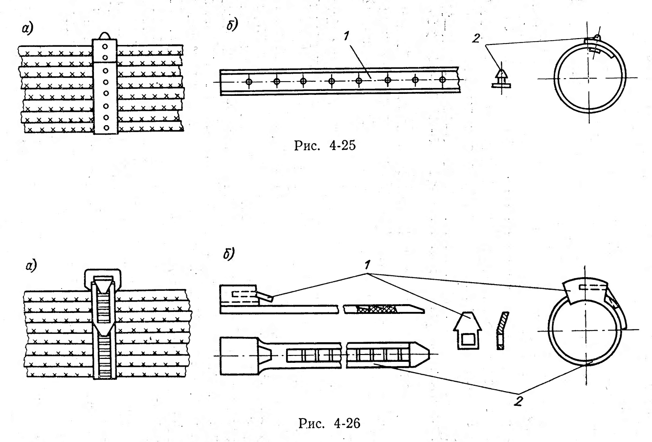
In Fig. 4-26, b shows a harness consisting of tape 2 made of polyethylene grade 20 906-040 by pressing. On one plane of the tape there are teeth with an inclination. A metal clamp 1 is installed in the head of the tape. When knitting a rope, the clamp freely passes the end of the tape through the hole, sliding along the inclinations of the teeth. In the opposite direction, the tape is held in place by a clamp.
Harnesses with a diameter of more than 75 mm should be placed in special plastic polyvinyl chloride perforated boxes. Knitting of bundles with threads is allowed. The knitting pitch and the number of threads, depending on the diameter of the bundle of wires with a cross-section of 0.35 mm 2 or more, are selected in accordance with the data given below:
For wires with a cross-section of less than 0.35 mm 2, the knitting step is selected depending on the number of wires in the bundle:
On curved sections, knitting steps should be reduced depending on the diameter of the strand and the bending radius. At the beginning and end of the tourniquet, bandages should be made, consisting of two to five turns of thread.
At many electrical equipment manufacturing plants, semi-automatic pistols are used for continuous knitting of bundles with a diameter of up to 26 mm with nylon threads. The productivity of automatic knitting is 400-500 mm/min with a knitting pitch of 5 mm.
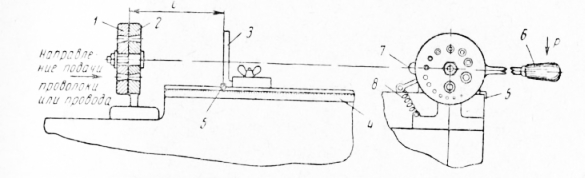
An example of knitting a tourniquet is shown in Fig. 4-27. If the harness is made of wires with cotton or silk insulation, then in order to protect the wires from moisture, the entire bundle must be impregnated with a moisture-repellent composition. Harnesses consisting of wires with polyethylene or fluoroplastic insulation that do not have a braid of yarn, for example wires of the MPM, MPKM, MGTF, etc., due to their cold fluidity, should be wrapped with tapes or films to prevent the insulation from being pressed through by threads during the manufacturing process and storage of the product. In order to prevent twisting of the harness during the winding process, the harness should be wrapped without removing it from the template. The beginning and end of the winding must be secured with a thread bandage and glued with HVK-2a glue.
For knitting bundles consisting of wires that, in addition to insulation made of polyvinyl chloride, polyethylene or other material, have a winding of silk, glass or cotton yarn, cotton threads No. 00, cords with a diameter of 0.5-2 mm, threads No. 9 should be used .5 linen, boiled nylon threads 3K, glass threads No. 10, polyvinyl chloride tubes with a diameter of 1 mm. Before knitting, cords and threads should be rubbed with ceresin or wax.
Before and after branching the tourniquet, bandages should be made from two or three adjacent loops.
From the influence of high temperatures, bundles (wires) should be protected with heat-protective material, for example, corded asbestos, fluoroplastic film, glass tape, or put on asbestos covers or tubes. 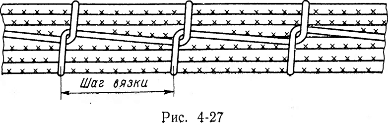
In single and small-scale production, the method of cutting wires and cables locally, i.e. directly in the body or frame of the device, is still preserved. This method of cutting wires is not very productive due to the fact that the movements of installers are limited to parts, assemblies, walls of frames and boxes electrical apparatus. 
Rice. 4-28
However, this method of cutting wires is used at electrical industry enterprises where, according to technical and economic indicators, it is unprofitable to switch to template cutting of wires.
TO category:
Production of radio equipment
Preparation of installation wires, cables and harnesses
Preparation of installation wires begins with straightening (aligning) the wires supplied to the plant in coils. After this, the wire is cut into pieces of the required length (indicated in the technical documentation).
At installation work splicing of wires from separate sections is not allowed. The brand of wire, its cross-section and color are also determined according to the technical documentation.
The method of preparing installation wires depends mainly on the scale of production. In individual production, the wire is cut with scissors or wire cutters according to a scale ruler. In mass production, various devices and machines are widely used for measuring wire cutting, significantly increasing labor productivity and the accuracy of this operation.
In Fig. 1 shows scissors for measuring wire cutting, characterized by high productivity with a cutting accuracy of +0.5 mm. The scissors have movable and fixed disks with holes of various diameters, a stop and a handle. When the scissors are not in working position, the holes in the disks, due to the presence of a latch and a tension spring, coincide. Cutting a batch of workpieces is preceded by setting the stop using the arrow to the required length; Readings are made using a graduated ruler. Then select the required hole on the disk according to the diameter of the wire, thread the wire into it until it stops; by pressing on the handle, rigidly connected to the movable disk, the workpieces are cut.
Rice. 1. Scissors for measuring wire cutting: 1 - movable disk, 2 - fixed disk. 3 - stop, 4 - ruler, 5 - arrow, 6 - handle, 7 - lock, 8 - spring
Cutting and stripping the ends of installation wires in mass production conditions is performed on a special machine (Fig. 2). The productivity of such a machine is 5500 wires per hour.
After cutting, the installation wires and cables go to end termination, which consists of the following operations:
— stripping the ends from insulation and shielding braiding, removing the oxide film, twisting the wires, tinning and securing the ends of the insulation.
The method of sealing the ends depends on a number of factors:
- brand of wire or cable used, design features of installation and its components, operating conditions of radio equipment, as well as the scale of production.
Stripping the wire from insulation should be carried out to such a length that would ensure reliable fastening of the wires to the contact petals without unnecessary technological waste. Practice shows that for most connections, stripping the insulation on a section of wire 7-10 mm long is sufficient. You cannot strip the insulation with a knife, as you can cut the current-carrying core of the wire.
The insulation of the wire to a certain extent determines the method of stripping.
Textile, plastic and film insulation is removed from the wires using one of the following methods:
- from wires MGV, MGVL, MGVSL, BPT-250, TM-250, PMV, PMOV (with internal fiberglass insulation), BPVL, MCSL - by cutting on a machine:
- from wires MGV, MGVL, BPVL, PVL, PMV, PMOV (with internal insulation made of cotton fiber), PMVG, MGShV, MGL, MOG - by electric firing method on an automatic machine simultaneously with measured cutting of workpieces or on a special device installed on the installer’s table and controlled by two foot pedals located under the table.

Rice. 3. Automatic machine for cutting and stripping the ends of installation wires

Rice. 4. Stripping the insulation from the end of the wire: 1 - insulation, 2 - core
The device has racks on which parallel columns 3 are mounted. C right side the right jaw 2 is fixedly fixed on the columns, the left jaw 1 on brass bushings slides freely along the columns. The ribbed part of the jaws is used to clamp the insulation at the time of its removal. Wire holders with copper pins are attached to the sponge-l. Power is supplied to the pins: constantan wire heaters are attached
screws. Cable connections are attached to the holders, with the help of which you can move the movable jaw to the right or left, moving or spreading the loop heaters, to which a voltage of 3-4 V is supplied from a step-down transformer. The pedals are used to set the heaters in a position in which a gap is formed between them, where the wire is inserted. By pressing the left pedal of the device, the loops of the heaters are brought together, thereby firing the insulation. Nippers and knives for electrical firing of insulation, working on the same principle as the described device, have become widespread in factories. Insulation from single wires MGV, MGVL, MGVSL, BPVL, BPT-250, G1VL, G1MV, PMOV (with internal fiberglass insulation), MCSL, LPL, MOG, TM-250 is removed with special pliers.
The enamel insulation is removed:
- from PET, PEL wires - with sanding paper, scraper, etc.;
- with PEV and PEM wire - dipping the ends of the wire into formic acid and then wiping with a soft cloth;
- With stranded wires LESHO and LESHD - by heating the fluffy end of the wire in the upper part of the flame of an alcohol burner to a light straw glow and quickly dipping into alcohol with a strength of at least 94°, followed by wiping with a soft rag.
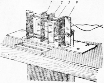
Rice. 5. Device for removing insulation from installation wires by firing: 1-movable sponge. 2 - stationary sponge. 3 - column, 4 - rack

Rice. 6. Pliers for removing insulation from the ends of installation wires

Rice. 177. Pliers for removing insulation from the ends of installation wires: 1 - square, 2 - knives, 4 - handle, 6 - clamp
In addition to the methods discussed, heating and mechanical devices are used to remove enamel insulation.
The heating device is a porcelain tube on which a heating coil is wound. The tube is secured to a wooden handle. Power is supplied through a step-down transformer. To remove the insulation, the ends of the wire are inserted into a heated porcelain tube, which burns the enamel.

Rice. 8. Mechanical device for stripping wires with enamel insulation
Mechanical devices designed to remove enamel insulation include a device with metal brushes (Fig. 8), which rotate using an electric motor in opposite directions. Using the set screws, you can adjust the gap between the brushes. To remove the insulation, the end of the wire is brought through a hole in the protective casing to the rotating brushes. The insulation is removed in a few seconds. A machine with rotating metal brushes can be used to remove any insulation, including rubber and fiberglass.
To strip the ends of high-frequency RK cables, a semi-automatic device is used, with the help of which the insulation from the cable end is removed in stepwise steps according to the specified dimensions, depending on the cable design. The cutting of the ends of high-frequency cables is shown in Fig. 179.On the front panel of the machine there are sockets, behind which there are spindles with heads designed for cutting one of the insulation layers. The semi-automatic electric motor simultaneously rotates all spindles.
The first socket and the corresponding spindle with a head are designed for removing vinyl chloride insulation, the second - for removing shielding braid, the third - for removing cotton insulation (by firing), the fourth - for trimming polyethylene insulation and the fifth - for trimming rubber insulation. Thus, cables with vinyl chloride insulation are processed in slots 1, 2 and 4, and with cotton insulation - in slots 3, 2 and 5. When processing cables, the integrity (absence of cuts) of the conductor, internal insulation and shielding braid must be ensured. Dimensions a, b, e, d (see Fig. 9) are determined by the type of connector and must correspond to the sketches technological map or drawing.
The oxide film on the exposed part of the conductive layer is cleaned with a scraper (Fig. 10) or medium-grain sandpaper. The stripped core is tinned with POS-40 solder 5-7 mm from the end.
The ends of the outer textile braid of the RK-44 and RK-45 cables are secured with thread No. 00, and then covered with nitroglue. If it is necessary to tin the ends of the cable shielding, they are immersed in molten solder or tinned with an electric soldering iron.
The ends of multi-core installation wires, for example MGV, BPVL, MGVL and others, are pre-twisted. For twisting, use a special device shown in Fig. eleven.
The stripped end of the mounting wire is fed through the guide bushing until it comes into contact with a rapidly rotating spring clamp element mounted on the motor shaft.
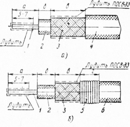
Rice. 9. Cutting the ends of high-frequency cables: a - RK cables, b - RK-44 (RK-45) cables; 1-core, 2-insulation, 3-shielding braid, 4-plastic insulation, 5-cotton thread No. 00. 6-trickile braid

Rice. 10. Stripping the RK cable core from the oxide film: 1 - metal stand, 2 - core, 3 - scraper
The stripped and twisted ends of the installation wires are subjected to hot tinning: immersed in an electric bath with molten G10S-40 or POS-61 solder for 1-2 seconds. The tinning area is first coated with an acid-free flux, for example an alcohol solution of rosin.

Rice. 11. Device for twisting wire strands before servicing 1 - guide sleeve, 2 - clamping element, 3 - electric motor
Rice. 12. Fastening the wire insulation with thread (braiding): a - fastening the first turn, b - laying subsequent turns, c - tightening the turns and cutting off the ends of the threads; 1-wire, 2 - cotton thread No. 20

Rice. 13. Fastening the wire insulation with a piece of tube: 1 - core, 2 - polyvinyl chloride tube, 3 - insulation
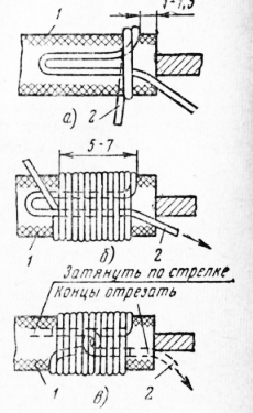
Banding consists of winding a layer of threads onto the insulation and securing them appropriately (Fig. 12). The plaiting is done with colored cotton or silk threads, which are then coated with BF-4 glue or nitro varnish. The use of a semi-automatic machine allows you to mechanize this process and dramatically reduce the labor intensity of the operation.
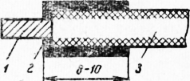
More productive and in a quality way The cotton insulation at the ends of the wire is sealed using vinyl chloride, rubber or linoxin tubes (Fig. 13).
To cut the tubes to the required length, use the machine shown in Fig. 14. The machine operates in an automatic cycle. Its productivity is 300 thousand blanks per shift. It allows you to cut tubes with a diameter of 2 to 6 mm into lengths of 8 to 20 mm.

Rice. 14. Machine for cutting insulating tubes: 1 - vinyl chloride tube, 2 and 5 - guide bushings, 3 - pressure roller, 4 and 7 - gears, 6 - knife, v - gear, 9 - fixed knife, 10 - drive roller
The main parts of the machine are two gears, on one of which a knife 6 is mounted, and on the shaft the second is a replaceable drive roller 10. To drive the gears, a small gear 8 is used, mounted on the motor shaft and rotating at a speed of 6000 rpm.
During operation of the machine, the vinyl chloride tube passes through the guide sleeve 2 and, falling on the replaceable drive roller 10, is pressed by the rubber pressure roller 3, and then fed into the second guide sleeve 5 and, finally, onto the blade of the stationary knife 9. With each revolution of the rotating knife, the vinyl chloride tube the tube is cut off. The length of the cut tubes is adjusted by selecting a replaceable steel roller with a sharp intersecting knurl.
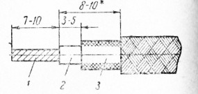
Sealing with nitro varnish is carried out on a section of wire 8-10 mm long (Fig. 15).
When securing the ends of the braid of wires BPVL, MGVL and MGVSL with nitro varnish or braiding, the braid is first shifted 3-5 mm from the cut point of the polyvinyl chloride insulation, and the excess is dispersed along the wire.
Rice. 15. Fastening the wire insulation with nitro-varnish: 1-core, 2 - nitro-varnish, 3 - insulation
When removing insulation from BPVL and MGVL wires by electric firing, the ends of the braid are sintered with the internal insulation, so there is no need to secure them.
The textile insulation of the PVL wire is removed in a section 8-10 mm long from the point where the rubber insulation is cut.

Rice. 16. Cutting the end of a shielded wire: 1 - core, 2 - insulation, 3 - braided shielding
Rice. 17. Cutting the end of the BPVLE wire (BPSHE, MGVLE, MTSSLE): 1-core, 2 - plasticate insulation, 3 - textile braid
The ends of the shielding braid are cut off by 20 mm with mounting scissors; to do this, move the edge of the braid, cut the braid lengthwise by 20 mm and carefully cut around it so that the cut is even and without protruding veins.
The ends of the shielding braid are sealed in several ways:
— by pulling the end of the wire through a hole made in the braid and connecting the free end of the braid to the body petal;
— soldering to the braid of an additional wire; winding bare tinned wire onto the braid and then soldering this place;
- fastening the shielding and textile braids with threads, followed by coating with nitro-glue and soldering the MGV wire to the middle of the shielding braid (this method is used for short wires).
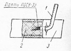
In the first case, proceed as follows: the end of the braid is expanded, moving to the right, and at a distance of 20 mm from the end of the wire, a hole with a diameter of 3-4 mm is made in the braid; The wire is passed through this hole and removed from the braid, and the free end of the braid is pulled out and pressed tightly against the insulation at the point where the wire exits. The end of the shielding braid is used to connect to the housing petal. In the case when the length of the braid is not sufficient, a piece of bare wire MM with a diameter of 0.5-0.8 mm is soldered to the end of the shielding braid, the end of which, approximately 4-6 mm long, is inserted into the braid from its end, crimped and soldered with POS-40 solder . In Fig. 188 shows an example of such a seal.

Rice. 18. Termination of the grounding end of the shielding braid: 1 - MM wire. 2 - shielding braid, 3 - nitro glue
Rice. 19. Soldering an additional wire to the shielding braid: 1 - core, 2 - plastic insulation, 3 - nitro varnish, 4 - MGV wire, 5 - polyvinyl chloride tube (if it is necessary to insulate the shielding braid), 6 - shielding braid, 7 - cotton thread No. 20, 8 - textile braid
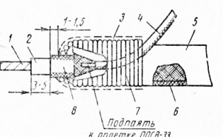
The method of soldering an additional wire to the shielding braid is shown in Fig. 19. A polyvinyl chloride tube is put on the braid and a wedge-shaped cut is made on it. At this point, the fluffed end of the MGV wire, 40-50 mm long, with a cross-section of 0.35 mm2, is soldered to the braid with POSV-33 solder. After this, the soldering area and the end of the shielding braid with the shifted end of the textile braid are secured with thread No. 20 and covered with nitroglue.
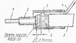
The method of winding an additional wire onto the shielding braid is shown in Fig. 20. 2-3 turns of bare tinned MM wire with a diameter of 0.5 mm are tightly wound around the end of the braid. One end of this wire is pressed with mounting pliers to the braid, and the other (40-50 mm long) is left free. The turns of the wire are soldered to the braid using POSV-33 solder using the dipping method. A linoxin tube is placed on the free end of the bare wire, and the soldering area is tightly covered with a piece of insulating tube 15-20 mm long.
The ends of the shielding and textile braids are secured with threads and nitro-glue. The fluffed end of the MGV wire is soldered to the middle of the shielding braid with POSV-33 solder. A vinyl chloride tube is put on the shielded wire, and the free end of the soldered wire is passed through a slot previously made in the middle of the tube, and then pulled out.
Typically, installation wires laid in one direction are tied into a common bundle with cotton or linen threads. Harness installation is characterized by increased mechanical strength, reduces the scatter of the circuit's own capacity and reduces the complexity of installation operations.

Rice. 21. Sealing the end of the shielding braid together with textile braiding 1 - nitro glue, 2 - textile braid, 3 - cotton thread No. 20, 4 - shielding braid
Rice. 22. Soldering an additional wire to the shielding braid: 1-MGV wire with a cross-section of 0.35 mm2, 2-shielding braid, 3-polyvinyl chloride tube
A sample of the harness is made at the design stage of the device. The following procedure for processing the tourniquet is recommended. On a chassis that is fully assembled and prepared for installation in accordance with the installation diagram and table installation connections lay out the wires. The ends of the wires are secured to the contact petals and marked. The wires are laid out in such a way that the finished harness does not lie on fasteners (nuts, screws, brackets, etc.) and, if possible, does not impede access to them; In addition, the insulation of the wires of the harness should not touch the contact petals of closely located parts.
Rice. 20. Winding an additional wire onto the shielding braid: 1 - core, 2 - insulator, 3 - polyvinyl chloride tube or tag, 4 - MGV wire with a cross section of 0.35 mm2 or MM & 0.5 mm wire 5 - polyvinyl chloride tube (if necessary insulate the shielding braid) 6 - shielding braid
The insulation of wires in places where the harness passes through holes in the chassis and screens is protected with polyvinyl chloride tubes, gaskets, as well as special rubber bushings (pistons) and insulators.
![]()
Rice. 24. Fastening the thread to the harness: 1 - thread, 2 - harness
Rice. 23. Tying wires into a bundle: I - wire, 2 - harness, 3 - branch of the harness, 4 - thread
The short wires are laid first and the longest ones last, so that the latter form the front side of the bundle. Shielded wires, not enclosed in PVC tubes, are placed in the middle of the bundle. If, according to the specifications, spare wires are provided in the bundle, they are laid on top of the longest length of the bundle.
There must be a reserve of wire length for fastening (20-25 mm at both ends) and the same reserve for re-fastening the ends of the wires in case of breaks. Thus, in addition to the distance between the wire connection points, another 40-50 mm is given in the direction of its laying. Before securing the second end, the length of the wire is measured, and the results are entered into the table of installation connections.
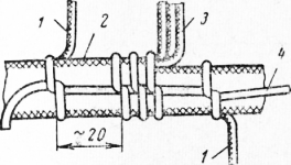
After laying out the wire harness, the wires are tied with a strong thread using a curved needle; loops should be knitted with tension at equal intervals (no more than 20 mm), as well as in places where the wires branch (Fig. 23). Fasten the beginning and end of the thread, as shown in Fig. 24.
When the knitting of the tourniquet is completed, it is removed from the device and straightened flat surface; the branches of the tourniquet, located in different planes, are bent 90° into the plane of the main part of the tourniquet.
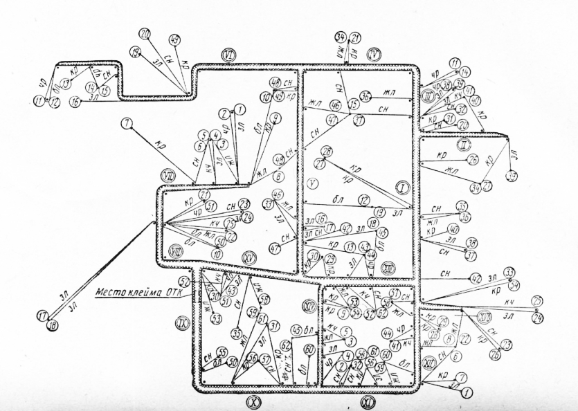
Rice. 25. Sketch of a harness
Then the tourniquet is placed on a sheet of drawing paper front side down and draw to life size.
An outline of the harness is used to make an experimental template, which is a sheet of plywood with a bundle drawn on it and driven into in the right places studs (Fig. 26). An experimental harness is knitted according to the template, and the layout of the wires on the template begins with spare and long working wires and ends with short ones, i.e. used reverse order wire layouts and reverse image of the harness. This is done to give the harness a more neat appearance: the knots made on the harness will not be noticeable after it is placed in the device.
An experienced harness is checked by placing it on the device chassis, and any inaccuracies are identified and corrected. Corrections are made to the harness sketch and the table of installation connections. The working template is made according to the corrected sketch of the harness.
In mass production, harnesses are made as follows: installation wires, which have been stripped, tinning and sealed at the ends, are laid on a template according to the connection table containing information about the brand, cross-sections, serial numbers and colors of the wires. Laying the wire begins by securing it to the initial stud.
Then the wire is laid according to the harness diagram, bending it at the corner studs, and ends with fastening to the end stud. The start and end pins have the same number. When all the wires are laid, they are tied with linen threads. The connected harness is removed from the template and the probe is used to check the correct placement of the wires. Samples of bundles are shown in Fig. 27.
In cases where increased demands are placed on the mechanical strength and moisture resistance of the bundles, they are tied with keeper tape and impregnated with varnish.
Electrified templates, which are widely used in radio factories, are more convenient to use; they significantly reduce the labor intensity of the harness manufacturing process and reduce possible defects.

Rice. 26. Template for laying out harnesses
In the electrified template, the end pins are replaced with button clips, into which green signal lights are mounted. Sometimes the light bulbs are located next to the clamps near the digital designations of the ends of the mounting wires. The template contains a table of connections. Red indicator lights are installed next to the designation of each connection. The installation is powered by a voltage corresponding to the voltage of the signal lights.

Rice. 27. Harnesses
Installation of installation wires on an electrified template is carried out as follows. When the template is plugged into the network, two green lights on the clamps between which the first wire needs to be laid light up. To secure the end of the wire, press the clamp button, opening the groove in it into which the wire is inserted; the green signal light goes out. After laying the wire along the contour of the harness, secure the second end; the green light of the second button goes out, but at the same time the red control light on the connection table lights up, indicating that the wire is laid correctly. At the same time, two green lights of those button-clamps light up, between which the next installation wire needs to be laid, etc. If the harness is laid correctly, only the control red lights of the connection table will light up.
Some radio factories have developed automatic machines for laying out harnesses.
The ends of the wires in bundles and interconnect cables are marked using wire insulation of various colors, tags made of multi-colored nitro enamels, tips made of colored or numbered polyvinyl chloride tubes, removable tags, adhesive polyvinyl chloride tape on which numbers are applied (a bandage of marking adhesive tape is applied to the wires and cores cable 1.5-3 turns).

Rice. 28. Typical scheme electpiLinned template
Send your good work in the knowledge base is simple. Use the form below
Students, graduate students, young scientists who use the knowledge base in their studies and work will be very grateful to you.
Posted on http://www.allbest.ru/
1. Technical characteristics of the production facility
Technical characteristics The production object for which this technological process is being developed is the production of harnesses.
General information about harnesses and their manufacturing technology
Harness installation is electrical installation EVA nodes using volumetric insulated wires, combined into a bundle.
The designs of the harnesses are determined by the design features of the frames and the requirements for maintenance and repair of equipment. The bundles are divided into inter-block and intra-block, which, in turn, are divided into flat, volumetric, with movable branches.
They are also distinguished by the degree of complexity: the number of branches and closed branches. Harness installation is carried out using installation wires and cables various types and appointments. The insulation of the wires can be fibrous from nylon threads (MSHDL, MGSh, MGShD) or fiberglass (MGSL, MGSLE); polyvinyl chloride (PMV, MGV) and fibrous polyvinyl chloride (MShV, MGShV, LPBL), plastic in the form of a polyvinyl chloride shell (MKSh, MPKSh); rubber (LPRGS, PRP, APRF, PRG) and fluoroplastic (MGTF). The choice of insulation is determined electrical voltage and operating conditions of the equipment.
At normal temperatures and humidity, wires with fiberglass or polyvinyl chloride insulation are used, at elevated temperatures and humidity - with fiberglass or fluoroplastic insulation.
If protection from external electrostatic fields is necessary, installation is carried out using shielded wires and cables with mandatory grounding of each shield.
Some of the installation wires, especially those with rubber insulation, are supplied with tinned conductors. This saves electrical resistance and mechanical - strength copper wire, located in rubber or vulcanized rubber, and speeds up the process of preparing wires for installation and soldering.
When designing, tolerances on the harness parameters can be determined analytically. When calculating the dimensional chain, take the wire with a reserve for resoldering and compensation of bends at the contact connections. Deviations of the closing link must take into account the tolerances for the geometric dimensions of the frame, the fastening of the harness, the length of the wires when laying out, and the installation of technological pins on the template.
The initial development of the harness design is carried out as follows. Wires are laid on the assembled frame according to the installation or schematic diagram. The ends of the wires are marked on both sides with tags indicating the route number (^ -2; 1 -6; 3 -5 etc.), after which their length is measured and the data is entered into the table of installation connections.
The sketch is used to develop a template and. in particular, to determine the placement of technological studs. The experimental harness is assembled on the template, and after its installation on the frame, the template is adjusted.
2. Manufacturability analysis
A technologically advanced design is one that is the easiest to manufacture at a minimum cost. The technological design should include:
1. The widest possible use of unified components, standardized and normalized parts of parts;
2. Possibly fewer parts of original and complex shapes and different names, as well as greater repeatability of parts of the same name;
3. Creation of rationally shaped parts with easily accessible surfaces for processing and sufficient rigidity in order to reduce the labor intensity and cost of the entire product;
4. It should be rational to assign the accuracy of size and surface roughness class;
5. Presence of base surfaces on parts;
6. Most rational way obtaining blanks for parts (castings, stampings with sizes and shapes that are as close as possible to finished parts, i.e., providing the highest material utilization rate and the least labor intensity);
7. Complete elimination or possibly less use of fitting work during assembly through the manufacture of interchangeable parts and mechanization, automation of assembly work;
8. Simplification of assembly and the possibility of parallel assembly in time and space individual parts products;
9. The design should be easy to assemble and disassemble, and also provide access to any mechanism for adjustment, lubrication, and repair.
The design being developed is technologically advanced because it provides:
1. Possibly fewer parts of original and complex shapes and different names, as well as greater repeatability of parts of the same name;
2. Creation of rationally shaped parts with easily accessible surfaces for processing and sufficient rigidity in order to reduce the labor intensity and cost of the entire product;
3. Simplification of assembly and the possibility of parallel assembly of individual parts of the product in time and space;
4. Complete elimination or possibly less use of fitting work during assembly through the manufacture of interchangeable parts and mechanization, automation of assembly work.
3. Technological route for manufacturing a harness
The technological route for manufacturing a harness is the following sequence of operations:
1. Preparatory operation
2. Equipment
3. Preparation of installation wires
4. Layout of wires on the template
5. Knitting a tourniquet
6. Control
4. Detailed description of basic operations
1. Preparatory operation
2. Equipment
3 . Ppreparation of installation wires
Preparation of installation wires consists of the following operations: measuring cutting, removing insulation and sealing the ends of wires, marking, maintenance and twisting of wires. If the technological process provides for the continuous layout of the wire on the template, then cutting, removing insulation and sealing the ends are carried out after the formation of the bundle.
Wire cutting is done manually simple tools(scissors, wire cutters), determining the length of the wire using a sample or using a ruler. In mass production this operation is automated. Automatic machines for measuring cutting and simultaneous removal of insulation from the ends of the wire are universal.
Depending on the type of insulation used various ways stripping: notch , electric firing or thermal softening With subsequent mechanical tightening of the insulation, and certain methods of sealing the ends of the wires.
Textile, plastic and film insulation is removed by cutting or electrical firing. Removing multilayer insulation has a number of features. So, if there is fiberglass, the outer plastic insulation is removed by electric firing, and the inner (fiberglass) is unraveled, twisted and cut at a distance of 1 mm from the end external insulation. External textile braids require stepwise cutting of the ends of the wires. For example, between the cotton braid and the core of the wire, a section (3-10 mm) of the main polyvinyl chloride or rubber insulation is left. The end of the braid is secured with glue, an insulating tube or a thread bandage coated with glue.
Heat-resistant fluoroplastic insulation is cleaned by electric firing at an elevated temperature of the filament. This releases a toxic gas - fluorine, which must be removed from working area using a suction system.
Stripping should preserve the quality of the insulation that cannot be removed, eliminate cuts or breakage of current-carrying conductors, and be sufficiently productive. In addition to automatic wire cutting and insulation stripping machines, special devices for thermomechanical stripping have been developed. Their main working elements are a filament and sponge knives.
The thread burns through the insulation when the wire is rotated around its axis. The sponges provide support for the wire when burning through the insulation, protect it from charring and the thread from mechanical damage, and together with the thread, ensure tightening of the insulation. The working edges of the jaws have a rounding radius of 0.08 mm and are polished, which will prevent cuts and breakage of current-carrying wires. Insulation strippers - can be equipped with a device for connecting to a vacuum system for suction of toxic products of insulation firing. The thermomechanical method allows you to remove insulation in one step from wires with a cross section of 0.07-0.35 mm 2.
For installation, shielded wires and radio frequency coaxial cables are used, which have an outer polyvinyl chloride coating on top of the shielding braid. Separating the coating by making a cut is labor-intensive and does not provide High Quality cutting ends.
The thermomechanical method allows you to remove the plastic insulation within 2-3 s without damaging the braid.
Knife sponges , equipped with heaters, penetrate the insulation and cover the diameter of the shielding braid. The insulation section inside the jaws heats up and expands, making it easy to remove by pulling it off the end of the wire.
Further cutting of the ends of shielded wires involves removing the shielded braiding in a certain area. One of the removal methods is circular cutting of the braid using a punch-die cutting pair
The working part of the punch is made in the form of a cone, turning into a sphere, which allows it to move quite easily inside the braid and ensures an even cut of the screen end on the sharp edges of the matrix . The method is implemented using devices of various designs, which allow cutting off in 3-4 s.
There are other ways to remove the shielding braid: a screw cut with rotating cutters and knives, cutting off the annular thickening of the braid.
To remove the end of the insulated wire through the shielding braid, use a sharp tool to push the core apart: the braid and pull the wire through the resulting hole. The most common tool is a grooved needle, which is inserted from the end of the shielded wire between the braid and the insulated wire. In a certain place, the tip of the needle pushes the braid apart and, using the eye of the needle, pulls out the end of the wire. This operation is performed in 3-4 seconds manually, guiding the needle using simple devices.
Sealing the ends of shielded wires involves grounding the screens or fixing the end of the braid relative to the wire. Grounding is carried out by attaching the free end of the braid to the frame elements, soldering an additional wire, applying a bandage of bare tinned wire and then soldering it. Soldering points are protected with insulating tubes.
The ungrounded braid is sealed between two insulating tubes, placing one under the shield and the other outside or between layers of insulating tape. The end of the braid is fixed with a thread bandage or a wire bandage, followed by soldering.
After removing the insulation, the bare ends of the wires are stripped, and the stranded cores are twisted at an angle of 15-300 to the wire axis. Last operation performed manually (core cross-section less than 0.11 mm2), with pliers or using special devices. The prepared ends of the wires are subjected to hot tinning by immersion in a bath of solder.
Marking of wires is necessary to facilitate installation, monitoring, troubleshooting and repair. Use wires with colored insulation and mark them with tags, adhesive tapes, or by applying markings directly to the wire insulation. Wires with colored insulation are usually used for indoor installation EVA. On electrical wiring diagrams, the color of the wiring wires is indicated by abbreviations or digital codes. Marking wires with adhesive tapes involves applying bandages made from this tape to the ends of the wires. Most Applications received marking using marking tags made from polyvinyl chloride tubes. The tag is attached to the end of the wire. In this case, the tag should overlap the edge of its insulating braid by 1-3 mm. Tags are placed on the wires in such a way that they are prevented from slipping due to shaking and vibration.
The symbols on the surface of the marking tags are specified in the electrical wiring diagrams and are carried out in accordance with industry standards. The production of tags (labeling, drying, cutting) is carried out on special machines. The installation wires are twisted to eliminate electrical interference and reduce the mutual influence of the circuits. The laying step is 10-40 mm and increases depending on the increase in the cross-section of the wire (0.05-0.75 mm 2). This operation is performed manually using a drill or on special machines.
4 . Layout of wires on the template
harness installation wire insulated
Structural and technological development of the harness makes it possible to manufacture it outside of EVA by laying out installation wires and cables on a template. Depending on the configuration of the bundles, flat or three-dimensional templates are used. The flat template is a base on which metal pins are located in accordance with the routing (see Fig. 2) and the configuration of the harness. Installation wires are laid between the studs. To protect the wires from damage, insulating tubes are placed on the studs. To fix the ends of the wires, the template design provides holes located next to the studs or special clamps. The volumetric template has additional elements, allowing for the layout of wires and their fixation in three planes.
There are universal flat templates that have holes located at a certain pitch and designed for installing studs. The layout of the studs on the template can be changed depending on the routing and configuration of the harness.
Designs of electrified templates have been developed that increase the productivity of manufacturing harnesses and eliminate installation errors. On such a template, the ends of the mounting wires are fixed with special clamps, electrically connected to the signal (green) and control (red) lamps. The lamps and clip-buttons are connected in such a way that when the template is plugged into the network, two lamps of the first route light up. At correct installation and the wire is fixed, the lights of the second route light up, etc. Electrified templates are more expensive than conventional ones, and it is advisable to use them in mass production of EVA.
When laying out the wires on the templates, some general rules. Several bundles should be made from wires of different sections, combining wires that are similar in diameter. insulation (for example, from 1 to 3 and from 3 to 6 mm). Shielded drives must be located inside the harness, so the layout begins with them. The screens are pre-cut and soldered; if there is an outer metal braid, it is wrapped with keeper tape or insulated with a tube. Short wires of small cross-sections are laid inside the bundle. Long wires are laid outside to form the front side. Spare wires should be located on top with access to their ends. These rules are quite easy to follow when laying out manually.
The sequence of wire layout on the template is manually set in the connection table, taking into account the listed rules. Often a drawing diagram indicating the routes is placed on the template. The end of the wire wound from the coil is marked with a tag and fixed on the template. The wire is cut in place after laying out between the studs and its end is marked. These transitions are repeated many times. The cutting of the ends in this sequence of operations is carried out after knitting the tourniquet. The manual layout on the template is carried out by the installer, and it is very labor-intensive. In mass production, it can be mechanized using a program-controlled device.
5 . Knitting plaits
Two (or more) insulated wires running parallel along the same route with a length of more than 50 mm must be tied into a bundle. The only exception may be an unacceptable increase in mutual interference in electrical circuits. For knitting, threads, cords, braid, insulating tapes, heat shrink tubing etc. The operation is carried out, as a rule, on a template. Knitting step t depends on the wire cross-section, number of wires n and diameter D tourniquet On curved sections, the pitch should be reduced depending on the diameter of the bend of the harness. In places where the wires branch, the binding should have 2-5 turns on all branches, the bandages should be made of 2-3 adjacent loops. The ends of the tourniquet must have bandages and end knots.
Knitting is carried out in one, two or more threads with tension manually or using devices. To reduce labor intensity, the process of tying strands is mechanized using pneumatic guns, and sometimes automated, tying strands on special semi-automatic machines.
To protect against mechanical damage, the harness is wrapped with insulating tape along its entire length or in a certain area. If it consists of wires with cotton or silk insulation, then to protect against moisture the harness is impregnated with a water-repellent compound. To protect against exposure high temperature or aggressive environment, the bundles are placed in tubular, tape, strip or woven casings. They are put on manually or on a machine after removing the harness from the template. Thus, knitting harnesses is no less labor-intensive than laying out and marking wires.
In addition to the use of various devices for mechanizing the operations of producing a harness, it is advisable to use conveyor lines in mass production conditions. In this case, the technological process is divided into a number of small operations. At each workplace, the entire layout of wires of the same section and brand is carried out. When determining the cycle of operation of the conveyor, they are guided by the laying operation based on the fact that the knitting operation is easier to subordinate to the chosen rhythm. For example, 3-5 minutes are spent on knitting 16-24 loops. Most often, the work cycle is 5 or 7.5 minutes.
The conveyor method of producing bundles has other features. The wires are laid out continuously, unwinding them from reels. A set of tags is first placed on the end of the wire to mark all routes performed at a given workplace.
Universal templates are used, equipped with studs both in places of bends and branches, and in places for subsequent cutting of wires. Layout routes are marked using special stencils placed on templates. For knitting strands, threads are used that can withstand sufficiently high tension forces. After knitting, the wires are cut, the harness is removed from the stencil, and the ends are cut.
The conveyor for making bundles is located in a horizontal plane, closed and transports templates using trolleys. In addition to templates, it is equipped with guns for tying harnesses, devices for stripping insulation, and a tinning installation. The conveyor method simplifies the operations performed at each workplace and reduces the overall labor intensity of manufacturing bundles. Its disadvantages are the tension of the wires during laying out and the deformation of the bundle after removal from the template, which worsens the quality of the knitting.
6 . Co.control
After manufacturing the harness, the quality of the termination of the ends of the wires and screens, the presence of markings, the absence of damage to the current-carrying conductors and insulation, and the quality of tinning are checked. The integrity of electrical circuits is checked using continuity probes. In circuits with a large number of intermediate connections, resistance is measured.
During inspection, ribbon cables are checked for the absence of conductor breaks, insulation resistance between conductors and ground buses, and the presence of electrical connections between the connector contacts and the ribbon wire.
For control, special automated stands have been developed, for example, with the number of checked points 90 and the main technological time checking the product for no more than 30 s. Control is carried out by checking electrical circuits, comparing the states of switches and then transferring the results to the light display panel. The stands can operate in automatic and manual modes.
Posted on Allbest.ru
Similar documents
Characteristics and technical specifications thyristor, its varieties, operating principle, symbol and application. The structure of an autotransformer, the principle of its operation. Maintenance and repair electric motors. Drawings of harnesses, cables and wires.
cheat sheet, added 01/20/2010
Installation, connection and termination of wires and cables, cable couplings. Connecting wires by crimping, twisting, followed by soldering and the bandage method. The design and principle of operation of a fluorescent lamp. Marking of diodes, thyristors, resistors.
practice report, added 03/26/2013
Preparation of electrical wiring routes. Overview of electrical wiring types. Cutting wires and cables. Connection and termination of wires. Organization of installation of electrical wiring of a residential building. Installation various types electrical wiring. Occupational health and safety.
course work, added 08/27/2010
Classification of electrical wiring. Organization of installation of electrical wiring. Connection and termination of wires. Quality control of contact connections. Methods for installing open tubeless electrical wiring, tubular wires, electrical wiring on trays and boxes.
course work, added 08/27/2010
Power, lighting, main and distribution wiring. Rules for installation and maintenance of electrical wiring, electrical installations, power panels; primary requirements. Installation of busbars in control panels; laying wires with air bags.
course work, added 03/17/2012
Power cables and wires - winding, installation, installation: technical requirements, purpose, labeling and application. Insulating materials used for installation wires. Marking of wires according to GOST. Control and special cables.
abstract, added 05/06/2008
Stages of complete assembly of electrical equipment. Calculation of load power. Open cable laying on a building base using staples. Installation steel pipes and wires, low-voltage complete devices and ballasts.
thesis, added 09/04/2010
Advantages and disadvantages of incandescent lamps, their types and applications, design and operation. Brands and characteristics of wires and cables used in electrical installation work. The mechanisms, tools and devices used; installation of incandescent lamps.
abstract, added 07/22/2010
Advantages fluorescent lamps, their types and application, structure and principle of operation. Brands and characteristics of wires and cables used in electrical installation work. The mechanisms, tools and devices used; installation of fluorescent lamps.
abstract, added 07/22/2010
Requirements for the installation of protection devices not resistant to maximum current values. Power box installation technology: marking the installation location of electrical equipment, fittings and panels, punching holes, installing fasteners, laying wires.
Development trends contract manufacturing in Europe and Russia have a lot in common. European production focuses on small batches, short time manufacturing. To attract customers, it has become traditional to equip contract manufacturing with harness sections to complete finished products (assembled printed circuit boards, electronic components) connection and connection devices.
The experience of our company in the market for the production of harnesses forces us to contact a respected publication in order to enable specialists in Russia to correctly select equipment for the production of harnesses. At making the right choice equipment completely covers your own needs and creates the opportunity for additional profit. This is important, since an enterprise equipped with high-tech and liquid equipment provides a stable income.
Modern tourniquet
In conditions of serial or mass production with a wide range of products, it is impossible to use soldering (welding), so only crimping is used. Over the past decades, a huge class of connectors using crimping has been developed. Tyco offers the widest range: there are proven and certified connector systems for almost any industry. The quality of crimping is much higher than soldering, if the operations are performed in strict accordance with the technology, the technology itself allows you to control the quality of each connection, so even in military equipment and in aviation, crimping is replacing soldering.
Harnesses modern car(Fig. 1) and washing machine have long become a high-tech product. The failure of one circuit leads to the failure of the entire system as a whole. Therefore, the highest demands are placed on the quality of the harness. The ideal tow production delivers products directly to the assembly line without input control. This is beneficial for both the consumer and the manufacturer.
Cost of ownership
A classic example for understanding the “cost of ownership” is a Mercedes car. Everyone knows that this is not a cheap car. But at the same time, taxis in Europe (and not only) are Mercedes. The reason is high reliability, significant service life, availability of spare parts (Fig. 2), and end result- reasonable and even low “cost of ownership” and high liquidity of a machine that is constantly in operation. Carrier companies in Russia have also realized that it is not the price, but the cost of ownership (!) that is important. Now Gazelles are being actively replaced in passenger transportation by both Mercedes and Fords, even GAZ has found an alternative to LCVs in England. The reasons are the low service life of domestic cars; their price after three years of operation (liquidity) drops to zero.
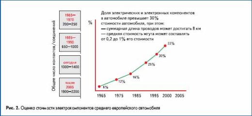
A similar situation is developing in the equipment market. Therefore, companies purchasing equipment for stable production give preference to well-known global companies and are guided by the experience of operating their equipment, for example, Leony, Yazaki, Valeo, etc.
Of course, there is a huge class of problems where the use of cheap or “budget” options is possible. Such consumers are focused on narrow product markets and prefer to fight for price at the expense of quality.
Classes of machines for making harness
The production of harness using automation systems is divided into several important stages- production of “subassemblies” or parts of the harness, assembly or “knitting” of the harness and its marking, control of parameters (checking circuits, electrical and even mechanical parameters). For each type of subassembly and depending on the expected performance, a machine of a certain class is selected:
- Tabletop machines, mechanizing operations, the quality of which cannot be guaranteed hand tool: machines for stripping complex (multilayer, coaxial) wires (cables), machines for crimping (pressing) the tip onto the core, machines for making twisted pairs. Such machines work “paired” with a human operator, the operator’s task is to correctly feed the workpiece, and the machine will perform a number of operations with high accuracy and reliability. The estimated figure for assessing efficiency is 8 thousand crimping operations per shift, this is the limit for a qualified operator of a press for installing tips.
- Automatic cutting-cleaning machines used for the manufacture of blanks for subassemblies. For normal operation machines are equipped additional devices wire feeding, laying finished products, markings. Most widely, machines of this class are used in the manufacture of harness parts in lighting engineering, energy, and transport engineering. There are no complex bundles and no large volumes. Productivity within 5 thousand workpieces per shift is more than reasonable for such production.
- Automatic lines focused on mass production. In one cycle, cutting and cleaning, marking, installation of tips, and selection of batches are performed on the workpiece. The KOMAX company, which produces equipment for complex automation, offers consumers automatic lines for special applications: for electronics, for harnesses household appliances, automotive harnesses, harnesses for aviation and transport engineering. Automatic lines allow the production of about 5 thousand blanks per hour.
- Automatic harness assembly machines- a separate class of equipment aimed at mass production of harnesses or subassemblies. Machines of this class produce harnesses for household appliances (IDC harnesses), for energy (parts of distribution cabinets), for automobiles (harnesses of ABS, sensors, FFC-FPC, for telecommunications).
Important Note
The class of machines (automatic or semi-automatic) used for the production of harness is determined by the productivity and functional purpose equipment. The characteristics of almost all manufacturers contain tables or graphs demonstrating the part of the harness, and using its example the number of workpieces per hour depending on the length is shown. Some equipment manufacturers, in pursuit of external effect, ignore one simple truth: raw material(wire or cable) has terminals mechanical properties, at high speeds When feeding the wire, its damage (breakage of internal wires) is inevitable. Therefore, the indicator of the number of blanks per hour is not an indicator of quality. Practice of application both foreign and domestic producers it confirms.
When setting maximum speed operating modes (in this case, built-in quality control systems, if any, are often turned off), a significant part of the finished product (in our experience - at least 12%) is defective. During the Electro-2004 exhibition, we conducted comparative tests of KODERA and KOMAX. The result is that the processing speed on KODERA is 10% higher, but more than 15% was wasted, while with KOMAX it was 0%.
Electronics Solutions
Electronics, as a rule, works with wires of small and ultra-small sections; the most common operations are: making tinning jumpers; installation of miniature tips.
KOMAX Kappa 225
Manufacturers of electronics and special equipment traditionally use small-section MGTFs. The “favorite” wire of electronics engineers is very capricious when processed on automatic machines (Fig. 3). But the KOMAX line of machines has a successful solution for processing it. Due to the use of four servos, this machine allows processing wires of large cross-sections (Table 1).

Table 1. Technical characteristics of KOMAX Kappa 225
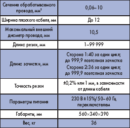
Almost the entire range of traditional wires in electronics is “closed” by this machine. Komax Kappa 225 is traditionally used in the production of harnesses (Table 2) for cars and household appliances, in auxiliary and procurement operations.
Table 2. Basic operations of KOMAX Kappa 225
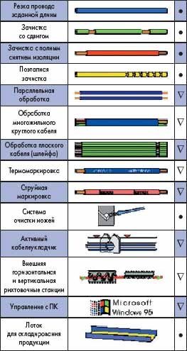
More than 10 years of experience in using these machines shows them high efficiency(Fig. 4) and reliability. Separately, it should be noted that machines are often purchased to solve special problems of the manufacturer of special equipment, but they become a source of additional profit and stable income, since they allow them to effectively fulfill third-party orders (Fig. 5).
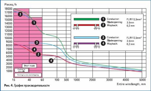
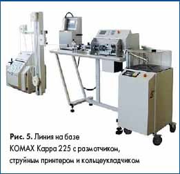
The company offers many standard solutions based on Kappa series machines: for the production of fiber optic patch cords, marking lines (thermal or inkjet) for wires (cables) for transport engineering, with additional equipment - good decision for making blanks for the production of lighting equipment.
KOMAX Gamma 255
Especially for electronics, Komax offers machines in the Gamma series (Fig. 6). The most interesting automatic processing machine for electronics engineers is the Komax Gamma 255. In this “universal”, you can process wires with a cross-section of 0.0123 mm, perform tinning, soldering (the “upper” limit is 2.5 mm2) and twisting the cores after stripping (Table 3, Fig. 7). In electronics, it is often necessary to make connections by soldering small jumpers. Especially for this, there is a cutting-stripping-soldering function on both sides (Fig. 8), the minimum length of the jumper is 15 mm. The machine is compact and requires a minimum of space for placement. In Europe, contract manufacturers of printed circuit boards, electronic components and devices prefer this machine.
Twisted pair is an alternative to coaxial wire in some measurement circuits.
The company has created the BT188 twisted-pair automatic cable manufacturing machine specifically for automotive and measurement systems. Operating experience in Russia has shown the high efficiency of its use, since attempts to perform the twisting operation using “improvised” means lead to damage to the insulation of the wire cores, deform the wire, there is no and cannot be a quality guarantee (Fig. 11).
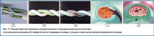
Specifications:
- Cross sections: 2×0.08 to 2×2.5 mm 2 ;
- With additional equipment: 3 or 4×0.08 to 2.5 mm 2;
- Twist length: 8–50 mm;
- Length of untwisted ends: 25–85 mm, adjustable;
- Length of finished twisted pair: 50–2500 mm (with additional equipment - up to 999.9 mm):
- Power supply: 115/230 V, 50/60 Hz;
- Pressure compressed air: 4–6 atm.;
- Dimensions (L×D×H): 3792×585×1230 mm;
- Productivity: about 330 pcs/h.
Within the framework of a review article, it is impossible to describe all KOMAX solutions for electrical engineering, automotive industry, a wide range of machines for wire processing, assembly automation for medicine, solar panels, and even knives (the famous VictryNox), so only “live” solutions for electronics are presented here.
Machines for advanced technologies
IDC (Insulation Displacement Contact) connectors first appeared in electronics. The idea of “slotted” contacts has proven to be tenacious; now IDC connectors are widely used in electronics, household appliances and the automotive industry. Connectors have appeared that can withstand up to 10 A - and this is not the limit. The use of IDC connectors has made it possible to significantly reduce the harness manufacturing cycle.
These connectors are most widely used in the production of household appliances and electronics.
In the line of automatic machines for IDC, KOMAX has several solutions (automatic lines, automatic harness assembly machines) - machines of the Zeta and Lambda series.
For semi-automatic operation, we recommend Stocko semi-automatic machines (Germany), and for hand assembled(gaskets) IDC connectors - Tyco tool.
KOMAX and Stocko machines are equipped with connection quality control systems. In Fig. Figure 12 shows a ground section of the IDC connection.
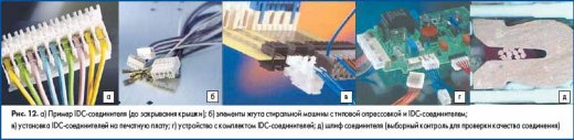
Appeal to electronic engineers
Unfortunately, we have to admit that specialists who select equipment do not always understand the technology for making harnesses using automatic and semi-automatic machines. This is largely due to the fact that there are fewer and fewer mechanical engineering specialists with practical experience. Often, having seen a machine “light and elegant”, they forget that the machine cannot work without a reliable and powerful frame, that the deformations that arise during the work “break” fashionable aluminum profiles, mechanical settings are lost.
When selecting equipment, try to get recommendations from the people who operate the equipment, not the seller. Unfortunately, sellers, for obvious reasons, focus on price rather than consumer properties. Request from suppliers (sellers) data on the service life and cost of main spare parts and Supplies, the cost of service (non-warranty) - an hour (day) of a specialist’s work, the minimum services that you will need to provide for his work. Very often these costs are significant (up to 1500 euros per day!). Evaluate separately the cost of downtime (!). In this case, you can get very interesting figures that will negate all the “pseudo-savings”.
When choosing tools for crimping (applicators), request data on the life of the parts. Too often, in pursuit of a low price, you can end up with an applicator that will not withstand even 10 thousand cycles. If you are interested in quality and high liquidity (the ability to sell), use only Mecal applicators (Italy) - their service life is more than 3 million cycles. Not only are they “indestructible”, they are also a liquid commodity.
Currently, we are on the verge of a boom in electronics, electrical engineering, and automotive manufacturing. Companies that have started producing cars and household appliances in Russia will reach their design capacity in 2008–2009. All are bound by obligations with the Russian Government to localize their production. Production logistics itself shows that importing (even from “cheap” China) parts and assemblies for SKD assembly will become unprofitable in the near future. The conveyor is aimed at the domestic market, production is focused on sales, so keeping huge stocks of components and parts becomes expensive and impractical: warehouse stocks reach tens of cubic meters and hundreds of thousands of euros!
In August-September, the MotorShow exhibition (MIMS and Interauto) was held in Moscow. This auto show turned out to be actually an exhibition of the Chinese automobile industry in Russia. The abundance of Chinese car manufacturers and auto components is amazing, impressive, shocking. Now most of car assembly plants and household appliance production according to requirements Russian Government must be localized. A wide field opens up for contract workers to interact with assembly plants. Cars are “stuffed” with electronics, entwined with wires and harnesses. I will give a short list of enterprises engaged in assembly in Russia:
- Cars (indicating the design capacity of some): Renault/Avtoframos - 160 thousand; Hyundai/Taganrog - 100 thousand; VW/Kaluga - 250 thousand; Ford/Vsevolozhsk - 120 thousand; Chery/AvtoTor (200), DM-Geely/Sverdlovsk region; KIA/Izhevsk; Toyota (200), Nissan (100), GM-DC/SPb-Shushary; SsangYong/Naberezhnye Chelny; Fiat/Elabuga; Chrysler/GAZ; FAW/Gzhel; GWC/Elabuga; Isuzu/Ulyanovsk - and that's not all.
- Production of household appliances St. Petersburg/BSH (Bosch-Siemens-Hausgerete), Electrolux; Orsk/Merloni, Lipetsk/Indesit and Stinol, Vladimir/BEKO, Kirov/Candy, Ruza/LG, Samsung.
The number of companies is not decreasing; there are similar projects in transport engineering and aviation. Electronics manufacturers have a wide field of activity and opportunities to expand their production. It is much easier for certified contract workers to fit into localization programs. Don't miss your chance, don't learn from your mistakes. Experience with assembly plants shows that there is a need for your services.
 (1 ratings, on average: 5,00 out of 5)