Socket for TV cable. Connecting a TV outlet: video, diagram, photo
First, let's get acquainted with what a coaxial cable is and how to choose it, which, after laying the wiring in the wall of a building or apartment, is subsequently connected to a TV outlet, and then connected to a TV or sat/TV receiver.
As you already understand, a coaxial cable for satellite and terrestrial antennas is a structure, the main part of which is the central copper core - the central conductor through which the satellite or terrestrial TV signal passes to the TV or sat/tv receiver. The braid and foil (Screen) are both a negative contact and protection against signal loss and electromagnetic interference in a coaxial TV cable.
These two components are directly used to connect to a TV outlet. Depending on the manufacturer's brand, components TV sockets, methods and types of installing the antenna cable to the socket may differ slightly from each other.
Let's consider connecting the most popular brands of electrical equipment such as Lezard and Legrand to TV sockets
For convenient installation of the cable to the TV socket, the cable reserve should be 15 cm
Connecting a Lezard TV socket.
Lezard sockets are the most affordable and of good quality, except for one thing.
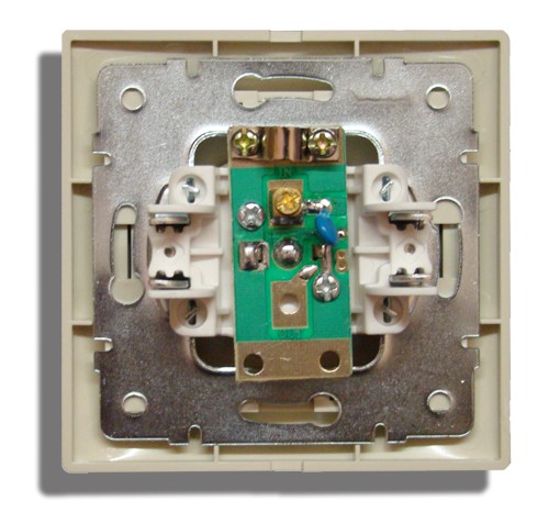
The basis of the Lezard socket is a printed circuit board, to which the coaxial antenna cable is connected.
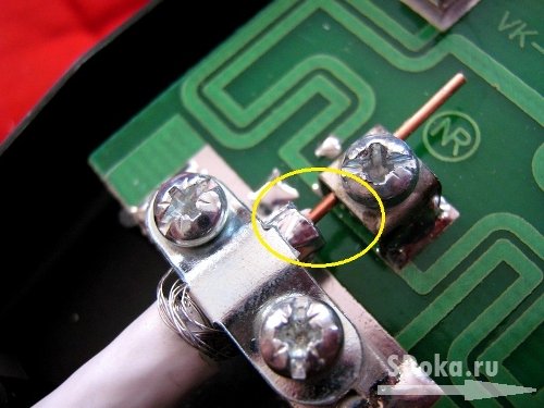
ATTENTION!!! Almost all Lezard brand TV sockets are on a printed circuit board electronic component- a capacitor that is located between the clamp of the central conductor core and the connector for connecting the TV cable. This component does not pass the supply voltage to an active terrestrial or satellite antenna. This type of TV socket is initially suitable only for passive antennas.
To use them for other types of antennas, it is necessary to replace the filtering electronic component with a regular conductor, that is, short-circuit or solder a piece of ordinary wire instead of a capacitor. copper wire
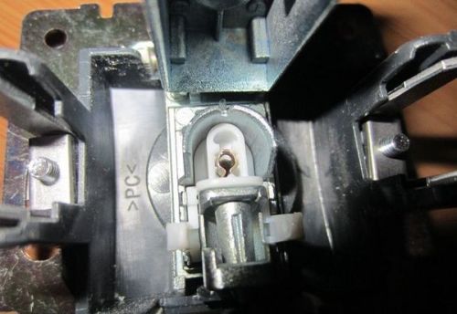
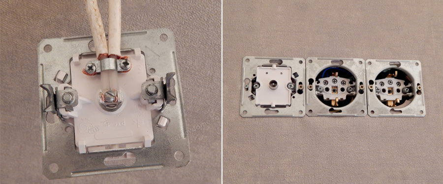
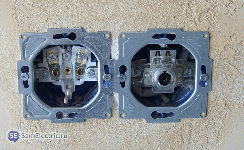
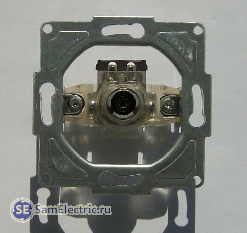
The front side of the Lezard TV socket with a connector for connecting a TV cable.

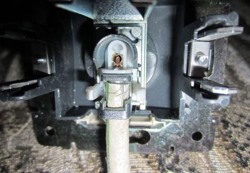
Mounting side with fastening elements for TV cable.
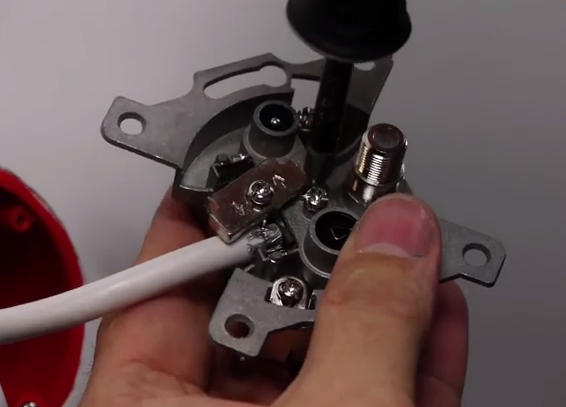
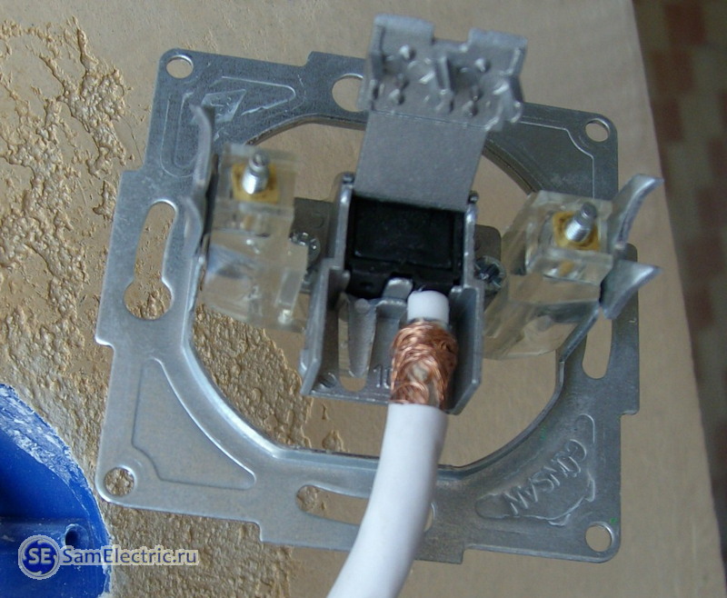
The connection consists of installing a signal conductor TV cable in the central terminal of the socket and fixing the screen with a bracket, as shown in the image below.

IMPORTANT!!! The central conductor through which the signal travels should not be shorted with braid or foil, that is, with a screen that protects against interference and signal loss in the cable.
Connecting a Legrand TV socket.
Quite high-quality TV sockets from the Legrand brand with in a convenient way connection but also at a decent price.
The process of connecting to Legrand TV sockets is as simplified as possible. This TV socket is designed in such a way as to minimize the number of steps when preparing the antenna cable for connection.
When connecting a Legrand TV outlet, the central core of the coaxial cable is clamped in the corresponding spring clamp, and the braid with foil (screen) is clamped with a folding fastener to the body.
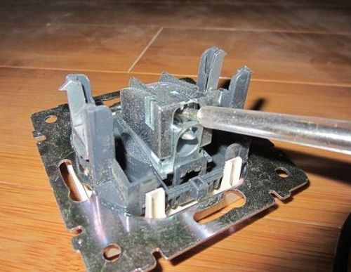
Having disassembled the outlet and seen its structure, you will immediately understand what you need to do to connect.
First, you need to open the mounting cover that covers the connection points of the coaxial TV cable. It is enough to carefully pry the cover with a screwdriver, thereby unfastening the latch.
Before connection, the external protective insulation and internal dielectric of the coaxial antenna cable are removed to a length of about 1 centimeter, exposing the central conductor, then the cable is inserted into the TV socket device, and the copper core is clamped with a self-clamping terminal.
The contact of the braid and foil of the antenna cable screen with the body of the TV socket occurs due to the plate (Fig. 3), which, when connecting the TV cable, fits under its outer insulator, firmly pressing against the screen (braid and foil) antenna coaxial cable.
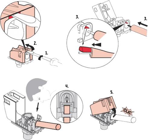
IMPORTANT!!! It is necessary to connect the center conductor - copper core, through which the signal travels so that there is no short circuit with the braid or foil, that is, with a screen that protects against interference and signal loss in the cable.
After connecting the TV cable to the TV socket, carefully place it in the socket box and secure it to it using 2 self-tapping screws. Then we tighten the screws of the TV socket clamp spacers, and then re-tighten the socket box screws until they stop:
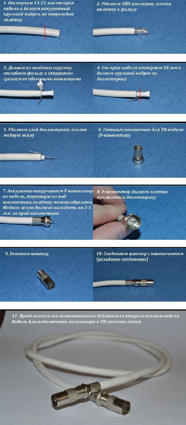
To do this, we need a piece of TV cable and several TV connectors - F-connector (2 pieces) F-"MALE" (right) and F-"MOM" (left) (photo below)

The "MALE" cable connector will be used to connect to a television socket (provided that the socket has a "MALE" plug as in the photo, although the opposite option may be available), and the "MALE" connector will be used to connect to the TV.
If the cable from the TV outlet will be connected to the satellite input of a TV with a CAM module or to a satellite receiver, then at the other end of the cable you will need not a “MALE” connector, but an F-connector.
A third option is also possible when the cable from the television outlet is connected not to the TV or satellite receiver, but to the power supply of the over-the-air antenna with an amplifier.
Depending on the distance from the outlet to the TV, satellite receiver or power supply, we measure the appropriate footage of the TV cable and cut off all excess. Next, prepare both ends of the cable for installing adapters. They are prepared in the same way as preparing a cable for connecting to satellite equipment using an F-connector (the process is shown in the photo below)
All that remains is to connect the TV socket to the TV using our universal cable and start scanning channels in the TV menu. This completes the process of connecting the television socket to the TV.
TV socket(TV socket) is a device designed to connect a TV to a television, satellite or radio network. Allows you to create aesthetic and easy-to-use connections (the cable is usually hidden in the walls or under floor plinth). It is possible to connect two or more devices in parallel, as well as the ability to increase the number of network sections. TV sockets differ in connection method, manufacturer, appearance and operating frequency.
Photos are clickable! Click on the product photo and the product page will open in front of you!
You think you've already figured it out what kind of device is this? Are you ready to buy a TV outlet? Do not hurry! Let's get everything straight first to avoid misunderstandings. Below we show and explain what types of TV sockets there are, their structure, as well as features that should be taken into account before choosing a TV socket.
Types of TV sockets
Television sockets, depending on the installation features, can be individual, pass-through or terminal.
Summarizing all of the above: feedthrough and end sockets are used if and only if there are multiple TVs on the network receiving television signals. You need TV socket to connect a TV (one)? Buy a single socket! Do you need sockets for, for example, four TVs? Buy 3 input sockets and 1 end socket. We've sorted out the types of television outlets, let's move on.
You can view the catalog of individual, pass-through, terminal TV sockets on our website.
TV socket device
Any television socket consists of several main parts:
- body (which is also called printed circuit board), necessary for connection to the antenna cable;
- front panel, which performs protective and aesthetic functions (can be selected in accordance with general style premises and personal design preferences);
- adder required to connect radio or satellite dish in addition to the main one;
- caliper - which serves as the basis for fastening all parts of the socket into a single structure, and also ensures reliable fixation of the socket in the installation box.
Features of choosing television sockets
Let's assume you trust the well-known brand Legrand Valena (we fully support you in your choice). What parameters does a buyer need to know when choosing Legrand Valena TV sockets? On sale you can find sockets with clock frequencies in the range from 5 to 2400 MHz. You should know that each type of signal (satellite, cable, radio) has its own operating frequency:
- Cable TV or TV from an outdoor antenna operates with a frequency from 45 to 1000 MHz;
- radio and television signals travel with a frequency from 92 to 108 MHz;
- with a frequency from 950 to 2500 MHz - cable and satellite TV signal in combination with a radio signal.
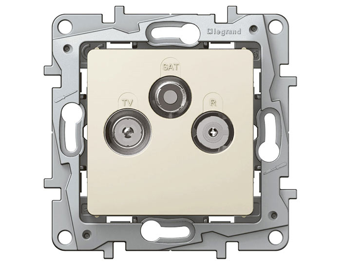
Thus, sockets should be selected according to the type of signal: R (radio), TV (cable or antenna television) and SAT ( satellite television). Very often, one socket combines several sockets at once: TV+R, TV+SAT, TV+R+SAT. Thanks to this, it is possible to sum the signals different standards and frequency ranges into a single cable to receive the required signal in the appropriate socket.
As for manufacturers, here the buyer can choose a device from dozens of companies, the most famous of which are: Legrand, ABB, Shneider and others. Such mechanisms are usually standardized and compatible with fittings from third-party brands.
Despite the regular updating of the market with new modifications of modern audio, video and TV equipment, there are traditional principles that ensure reliable signal transmission. One of them is the equipment of stationary sockets. We will try to figure out how to install a television outlet, but first we will analyze several related nuances.
Modern TV differs from its predecessors from the last century in its greater capabilities and versatility. This is not just a video signal transmitter, but part of a multifunctional multimedia system. It includes the broadcast of many domestic and foreign television channels, the ability to view photographs and videos from mobile devices, access to the Internet, use of game consoles.
With a huge load on the router wireless connection is not always reliable, so do not neglect the classic installation of a TV outlet. The choice of modern, wall-mounted modules is quite extensive. We recommend paying attention to series of brands such as Legrand, Schneider Electric, GIRA, IEK. They have a neat appearance, made of durable materials and do not cause difficulties during installation.
Standard module design
The installation of television equipment has some differences from the installation of electrical analogues and is considered separately, since the most important details– cable and sockets are also different. There are many designs even for products from the same manufacturer (for example, Legrand produces the popular Valena, Celian, Etika, Galea Life series), but there are no fundamental differences in the device.
Let's look at the structure of the socket using the example of the ABB Busch-Jaeger model:
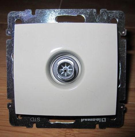
Externally, the design of almost all types of TV sockets is the same: a plastic strip that is attached with two miniature screws, and a TV input right in the center
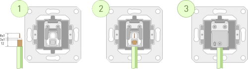
If we consider a sample from the Basic 55 series, it consists of the following parts:

Construction of a simple television socket: 1 – front panel, which serves as decorative and protective function; 2 – support that fixes the body and parts of the socket to each other; 3 – printed circuit board organizing the connection
The structure of the printed circuit board may differ - for more complex modules it contains electronic circuits. On the reverse side there is a mechanism responsible for fixing the antenna cable.
Types of sockets by purpose
Before installing electrical equipment, you need to decide on the choice of sockets for the TV on the wall. To make it easier to navigate the various modifications, manufacturers have identified three main types:
- simple (single);
- checkpoints;
- terminal.
The functional focus is inherent in the names of the categories; each of them has its own characteristics.
For example, to create the simplest circuit, which involves one single module that operates independently, you will need a simple socket. It is fundamentally different from the final one, so when purchasing, ask for a product of the specified type.

Assembly diagram of a simple socket that ensures normal signal flow when equipping a single point in the apartment. If you install another type instead, interference will occur
Simply put, if you have one TV in your room, to which one cable is connected, then this is your only possible variant. If you install several TVs in your apartment, but use a standard splitter, then simple sockets can also come in handy.
The structure of the pass-through socket is fundamentally different. It rather resembles a tee having 1 input and 2 parallel outputs. One output is intended for connecting a video device, the second is for a cable going further (either to the next TV, or to the next pass-through socket). The chain of pass-through modules always ends with the installation of a terminal type socket.
There is a danger of signal weakening when creating chains of a large number of pass-through modules. To maintain sufficient power, we recommend limiting yourself to 3-4 pieces.
Only a parallel connection through a splitter (hub) can provide a high-quality signal. Additional expenses for purchasing an additional cable will be paid off by excellent video playback
The purpose of the terminal socket is to close the circuit of the passages.
Minimum set for the living room
Previously, when installing a TV, nothing other than power supply was required, since the antenna was connected directly to the receiver and installed next to it or, to obtain a more powerful signal, it was brought outside, to the roof or to the balcony. Nowadays, one electrical outlet is not enough, since there are different data transmission standards (digital and analogue) that require their own connection.
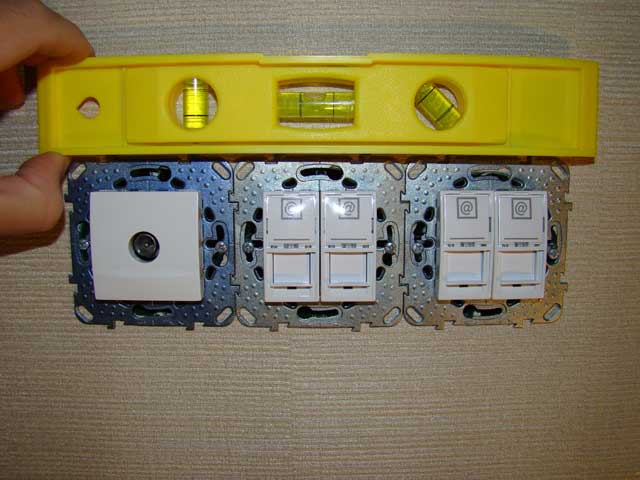
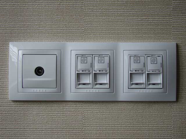
Instead of 1 socket, a whole block consisting of at least 4 pieces is installed.
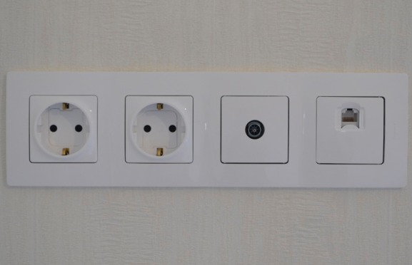
The minimum diagram for the room in which the TV is installed looks like this: 2 el. sockets, 1 TV socket, RJ-45 module for Internet
We recommend installing a block module for aesthetic reasons. If you initially only had an electrical outlet, and then a separate television outlet appeared next to it, followed by an Internet connection, it will look extremely sloppy, scattered, and the place will most likely be in plain sight. If renovations are planned, be sure to start with wiring and installing new equipment.
Two electrical sockets- this is also a minimum: one is intended for a TV, the second is for a digital set-top box or other equipment that is often connected to modern video players. The TV module provides communication with cable television or an antenna placed outside.
In addition, the antenna output is always a backup option. Suppose the digital set-top box is out of order or maintenance work is being carried out somewhere - thanks to the antenna cable, you always have the opportunity to watch a free package of standard TV channels.
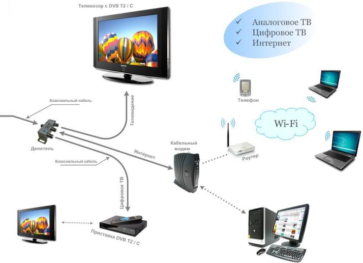
Universal connection diagram for media equipment with the ability to use analog TV, digital TV and access to an Internet connection (+)
The Internet input is designed to connect a digital set-top box or a signal supplied by the provider in a centralized mode. It is brought to him twisted pair from the router (and not from the common switchboard), which distributes the signal throughout the apartment.
Antenna cable difference
For a high-quality connection, in addition to correctly selected sockets, you will need an antenna coaxial cable, which has a special structure. Unlike 2- or 3-core electrical wire, it has one core for transmission TV signal and a protective shield that serves as a barrier to surrounding electromagnetic fields.
Externally, the television cable is a thick elastic wire round section, usually with PVC insulated black or white. For in-wall installation color external insulation doesn't matter.

Structure of a coaxial antenna cable: copper conductor for transmitting a TV signal, dielectric insulation, braided protective metal screen, outer plastic sheath
A thin insulating layer adjacent to the central core breaks the galvanic connection with the shielding braid. The screen, in turn, protects against electromagnetic interference and prevents the emission of sensitive high-frequency signals, while also serving as an additional conductor. If any of the components fail, video transmission will be disrupted.
Here are several types of cables that are suitable for laying under plaster or other finishing material:
- SAT 50 (SAT 703);
- RG-6 (and for external use);
- RG-11 (F1160BVM COMMSCOPE).
When purchasing, be sure to check the strength of the sheath, and during packaging and transportation, try not to bend the cable so as not to damage the integrity of the copper core and screen braid.
Connection diagram options
There are two main connection schemes - parallel (“star”) and serial (“loop” or loop-through). All the rest, no matter how complex and intricate they are, are combinations of these two main options. They resemble ordinary ones electrical circuits, but differ in lower voltage.
“Star” – several independent lines
Once upon a time we got by with one video receiver for the entire apartment, now there are televisions installed in almost every room. To connect all devices to a single cable leading from the panel or over-the-air antenna, a special signal distribution device is required - a splitter or splitter. This is a kind of switching organizer that has one input for an antenna cable and several outputs for connecting TVs.
The origin of the “talking” associative name for the parallel connection option becomes clear: the splitter is the center of the “star”, and all the cables extending from it are its “rays” (+)
The advantages of parallel connection are not only good signal quality, which is usually weakened by pass-through sockets. During installation, the splitter is attached to the most convenient location(for example, in a corridor), and it is easier to make branches from it to other rooms. If one of the sprout cables becomes unusable, the functionality of the rest of the network will not be affected.
There is an improved star amplifier solution that ensures video signal attenuation is minimized. The standard power supply is designed for 2-3 receivers, but usually there are more, so the amplifier compensates for the lack and ultimately improves the video signal.
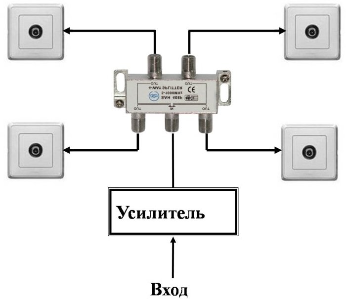
A standard amplifier (such as SAT Legrand) may be required in two cases: 1 – if there is a large number of working TVs, 2 – if the signal from the over-the-air antenna or cable provider is very weak
For parallel connections, either terminal or simple sockets are required. It is better to prefer the end ones to avoid interference if one of the TVs is not actively used. They differ from simple ones by the presence of wave impedance (75 Ohms), which can balance the signal.
"Loop" - pass-through sequential circuit
The pass-through scheme is considered cheaper, but of lower quality. It was actively used in previous years, but modern digital technologies have supplanted it, since they can only work according to parallel connection. It turns out that you can use a “daisy chain” connection only in one case - if you have exclusively analog television and changes are not expected in the near future.
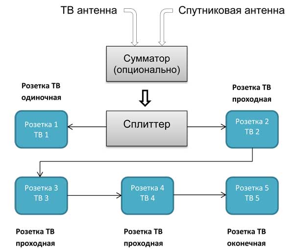
The sequential circuit assumes mandatory use pass-through sockets located one after another, but the last in the chain must be the final one
Pass-through modules are equipped with filters that dampen the reflected TV signal. The absence of a filter can be easily determined by the characteristic ripples on the TV screen. When choosing products, pay attention to characteristics such as pass-through attenuation (from 1.5 to 5 dB) and branch attenuation (from 10 to 15 dB); give preference to devices with the lowest parameters.
Please note that as the number of connections increases, the signal quality weakens, even if the network is provided with an amplifier or an auto-regulation system, so for 4-5 or more receivers it is better to use a parallel circuit. And carefully read the agreement with the provider: in some cases they limit the number of active points, and impose a fine for installing additional ones.
Optimal height
If you decide to place the TV on the wall, the installation height of the socket block is determined automatically - it is hidden behind the television panel. This installation method allows you to completely mask the inlets, connectors, and visible sections of cables. Wires hanging on the wall can ruin the design of the exquisite interior, besides, their open location poses a risk of breakage (small children will cut them, a dog will chew them, etc.).

Option correct installation TV: it is pressed as close as possible to the wall, all wires are hidden under the cladding, sockets are in a hidden space, right behind the screen
The mounting height of the sockets is based on the mounting height of the TV, which may vary slightly. Typically, television and video equipment is placed at eye level of a person sitting on a chair or on a sofa. The optimal distance is considered to be 1.2-1.4 m (from the floor surface to the center of the outlet). In relation to the TV - slightly below its top edge.
But there are also exceptions. For example, a kitchen video device is most often mounted a little higher, on free space, accordingly, sockets should be installed above the specified height.
Installation procedure for a simple TV socket
Before installing the socket, it is necessary to run a cable (for a simple single socket - the only cable leading from switchgear). It is disguised or in a closed way– under plaster (plasterboard, decorative panel), or open - on the surface of the wall, in a cable channel. The second option requires external (overhead) sockets.
For a sample, let's take a high-quality product from a French manufacturer.
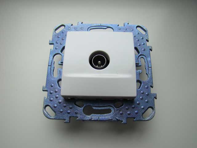
Socket for connecting a coaxial antenna cable from the famous French brand Schneider Electric. This is a simple (single) module MGU5.462.18ZD, designed to connect one TV
Before installation, use a drill with a round attachment to cut a hole and insert plastic box(socket box). A cable about 15 cm long should come out of the hole.
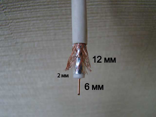
The end of the cable should be prepared: remove part of the outer insulation so that the copper core protrudes by about half a centimeter, and part of the shielding braid is also exposed
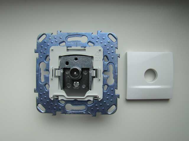
After separating the front panel, we find the clamping screw that ensures stability and unscrew it a little to make it easier to insert the antenna cable
Insert the cable in the direction of the arrow and fix it with a special clamp, tightening the screw.

Under the arrow there is a small through hole for connection control copper conductor. But for greater reliability, a visual inspection is not enough; to more effectively check the quality of the installation, you need to use a tester
Checking with a tester will eliminate the occurrence short circuit due to accidental contact of the braid with the conductor.
Carefully, trying not to disturb the position of the cable, insert the housing into the socket box, fasten it with fasteners and snap the front decorative panel into place. Using a level, level the position of the block
The result of assembly and installation is no protruding wires or unprotected connectors.
The socket block usually represents one long panel, divided into several functional sectors: for connecting a coaxial cable, RJ-45 Internet wire (twisted pair) or electrical cables
Installation of the pass-through module will be slightly different.
Features of parallel and pass-through circuits
If you are not limited to installing an outlet for one TV and want to use a “star” circuit, pay attention to the following nuances:
- First of all, we install the splitter, and only then the sockets.
- We connect one cable to each splitter output, which should end with the installation of one socket (simple or terminal).
- When installing simple modules, please note that they are not equipped with filters.
Watch the frequency. According to GOST (R 52023), the possible frequency must fall within the range from 40 to 1000 MHz, and some devices “narrow” these limits. For example, the operating range of DOCSIS v.2.0 is from 47 to 862 MHz, respectively, sockets support these restrictions.

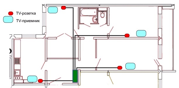
If you are the owner of a large two-story cottage, then cable routing for various purposes must be thought through before starting finishing works. The diagram shows an example of connecting various technical devices indicating the cable type (+)
If you are not interested in digital television and have chosen serial circuit connections, do not forget about the quantitative limitation.
The more sockets there are, the weaker the signal. Of the levels allowed by Russian GOST of 57-83 dB, already with 3-4 pieces installed, you exhaust the allotted limit (for each socket - about 15 dB).
Videos with examples of installing TV sockets
You can see how to choose and install modern antenna sockets correctly in the following videos.
Connecting the cable to a simple outlet:
Installation of Legrand socket block:
Features of sockets of the German brand WISI:
For self-installation To install a built-in TV socket, you must have the knowledge of an amateur electrician and be able to understand the types of wires and sockets. If you have designed a complex circuit using additional devices, then it is better to contact your provider regarding installation issues - only a specialist will be able to take into account all the nuances of the connection.
The principles for installing sockets for TV and conventional connectors are similar, since in both cases the same type of socket is used. There are only slight differences in the method of carrying out installation work. In this article we will look in detail at how to connect a TV outlet.
Types of television sockets
There are two types of television sockets: final (terminal) and pass-through. Connectors are also classified by purpose: for terrestrial TV (denoted as TV), for radio (R), for satellite TV (SAT). In addition, there are combined types of sockets on sale: TV (45-1000 MHz), TV+R (92-108 MHz), TV+SAT (950-2500 MHz), TV+R+SAT.
Advice! It is advisable that the socket be the same color as the power connectors - this will make it easier to fit it into the interior. If the sockets are installed in a single block, then not only the color, but also the manufacturer of the devices must be the same.
Terminal connectors are so named because they are the final node in the network. This type of TV sockets differs in signal high definition, absence of interference due to a wave impedance of 75 Ohms. The terminal connectors can work with several standards: either individually or in combination (TV, TV+R, TV+R+SAT).
Another type of connector is a pass-through TV socket. Such devices are used to receive a signal and further transport it to other connection points. Signal transmission between sockets is carried out via a coaxial cable. The device is equipped with a pair of sockets (one socket at the input and one at the output). The TV is connected at the input, and at the output there is a wire going to another consumer. In this case, the last socket in the circuit is always the final one. Pass-through connectors are not used to build circuits in which satellite signals are distributed due to technical incompatibility with for the most part decisions.
 The pass-through TV socket is no different from the terminal socket on the front panel. But on back side there are two connectors with arrows: input and output
 Connection diagrams
There are many schemes for connecting a TV connector. A splitter is used to process the signal. This device looks like a small box and performs the function of signal separation. As well as in telephone lines, when transmitting digital electrical signals, it is impossible to do without their separation.
The principle of operation of a splitter is to divide the signal into equal packets. Next, the divided segments are transmitted to the input part of the television connectors. The splitter is designed in such a way that all TVs receiving the signal, regardless of their number, will receive a signal of equal quality. As a result, within the same apartment there is no point in having a separate antenna for each TV.

The connection can be made in one of two ways:
- The “star” scheme, when the old cable is removed and the new one is laid through the splitter.
- Daisy chain circuit.
Below we will look at the question of how to connect an outlet, while paying attention to the advantages of the circuits under consideration.
Star pattern
This circuit uses a splitter that performs the function of branching the signal, breaking it into packets and amplifying it. The device is placed at the cable entrance to the living space from the entrance. Next, antenna conductors are distributed to consumers. Installing a TV outlet using this simple technology is most often used, since the splitter provides a number of advantages:
- The cable is located in a technically protected place, which is important both during installation work and during further preventive inspections.
- The signal is stable.
- Separated signal packages are uninterruptedly supplied to all television receivers in the apartment.

Daisy chain connection
This method of installing a TV outlet involves the use of a cable. The main cable is routed to any of the TVs in the house, and then it is routed to other receivers directly at the connector. The wiring is a branch into two or more parts (depending on the number of TVs available).
Connecting in this way is called daisy chain. In this case, the connectors connected by a cable must be feed-through, except for the last one, which is the terminal one.
The daisy chain circuit allows you to save on cable consumption, but it also has disadvantages. The disadvantage of a daisy chain system is that the quality on the first receiver will be higher than on subsequent ones. However, if the television signal is strong enough, the difference will be almost unnoticeable. In addition, one should take into account the fact that modern television equipment is equipped with the ability to amplify the signal, and this happens automatically.
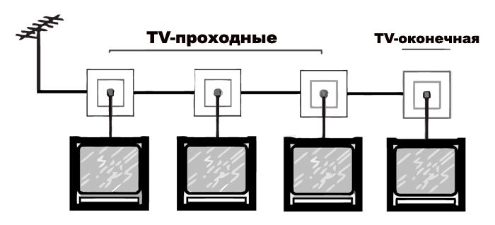 Daisy chain connection via pass-through television sockets
 So, the uneven distribution of the signal in this case can be considered an insignificant drawback. Other disadvantages of the loop system include the following:
- A circuit with pass-throughs and a terminal TV socket will cost more standard scheme"star".
- If the circuit breaks, all subsequent consumers are deprived of a television signal.
Installation using the example of a Schneider socket
As an example, let’s look at the installation of a pass-through socket from the French company “Schneider Electric” (socket model tv rj45). The task is to connect two TVs to one cable using a loop-through circuit.
When installing a socket for a TV cable, we provide a small excess of the cable itself - it should come out of the installation box. Next we clean small area insulating material on the cable. At the same time, we keep the central core and shielding braid intact.
We start by removing the front panel and slightly unscrew the clamping bolt. This is necessary to ensure that the cable exits freely through the hole.
There are arrows on the connector body. Insert the cable all the way in the direction indicated by the arrows. Then we press the cable with a clamping screw (tighten it). The cable must be securely fastened, but the screw must be tightened with care so as not to crush the line. We perform exactly the same manipulations with the second end. We install the connector in such a way as to avoid kinks on the cable.
Note! Before installing a television outlet, you should inspect the area where the wire is fixed for the possibility of a short circuit. main vein with braid.
When the cable is inserted and fixed, put it on front panel. The panel is fixed using special proprietary latches. Using a building level, we check the accuracy of the horizontal installation of the connector. If everything is in order, we finally fix the panel with fastening bolts and cover it with a frame.
Connecting the Lezard connector
Sockets from the Lezard company are inexpensive and differ good quality. However, when choosing Lezard products, you need to take into account the presence of a printed circuit board on it. The fact is that the boards are equipped with a component such as a capacitor. This part is located next to the center core retainer and the cable connector. The capacitor is impermeable to the supply voltage that must be supplied to the active antenna. Therefore, such connectors are suitable exclusively for passive antennas.
If you still want to adapt such a socket for an active antenna, you need to install a standard conductor instead of a filter capacitor. This is done by short-circuiting and soldering a piece of copper wire instead of the capacitor.
The actual connection of a TV socket consists of installing the signal conductor of the TV cable in the central socket terminal. You also need to secure the screen with a bracket.
Note! The main conductor that transmits the signal must not be short-circuited with the braid. Otherwise, the screen that protects against loss of the television signal in the cable will be damaged.
Connecting the Legrand connector
The TV socket from the French manufacturer Legrand is easy to connect, but also quite expensive.
When connecting the connector, fix the central cable core in a special spring clamp. We press the foil braid to the body using a folding fastener.
We remove the fastening cover, which covers the connection areas of the coaxial cable. To do this, carefully pry off the cover with a screwdriver, thereby releasing the latch.
We remove the outer insulating layer and the inner dielectric material cable is about a centimeter in length. We direct the cable into the connector, and fix the copper core with a self-clamping terminal.
Note! Contact of the braid with the socket body is achieved thanks to a plate that connects to its outer insulator, firmly pressing against the cable screen.
When the cable is connected to the connector, install the latter in the socket box. We secure the socket with a pair of self-tapping screws. Next, we clamp the screws with spacers of the socket clamps. We tighten the screws of the socket until they stop. Place the front panel of the connector in its proper place. The TV socket on the wall is installed and ready for use.
In this article we will look at this necessary thing in the house, like a socket for connecting a TV antenna, otherwise - a TV socket.
Installing a TV outlet is a must!
IN modern house There are often 2-3 TVs, and it’s no longer fashionable to entangle TV cables in a room. Previously, when there was one collective TV antenna and one TV, residents put up with a TV cable through the entire apartment. IN as a last resort, laid the antenna cable in or under the baseboard.
Now, in the age of television and the Internet, there are too many wires to not take care to keep them out of sight.
The truth I preach to my clients is that it is better to electrical wires before plastering (first stage electrical installation work) lay the antenna cable, as well as wires for connecting the telephone and the Internet, and other low-current, such as security, fire, video surveillance and smart home. At the same time, given that this is planned to be done “forever”, the low-current wires must be of high quality and laid accordingly. I recommend laying the cable for the TV signal SAT 703, or another high-quality one (ask in the store, just not RG-6 and especially not RK), it can be laid under the plaster without additional protection.
It is better not to deal with this matter on your own, without experience, but rather with an antenna specialist.
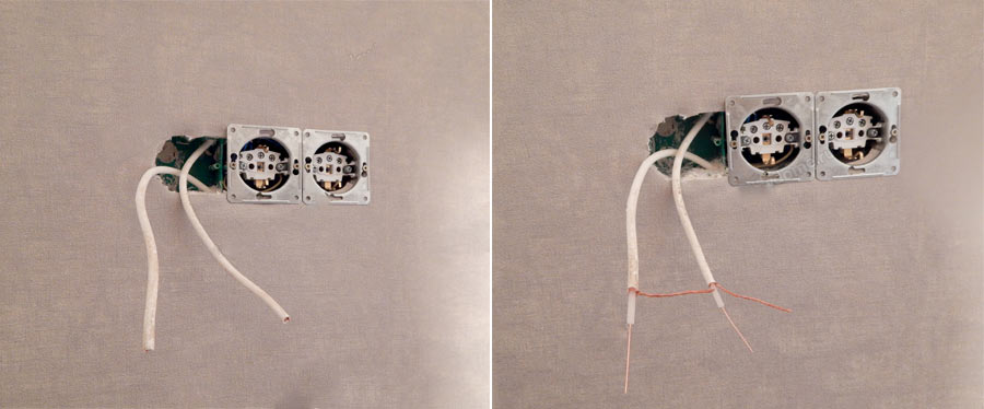
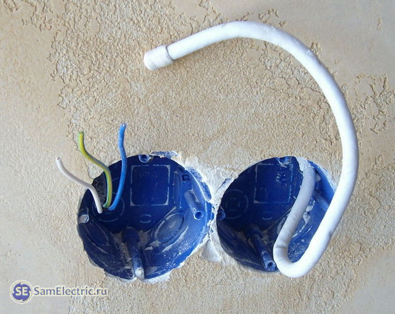
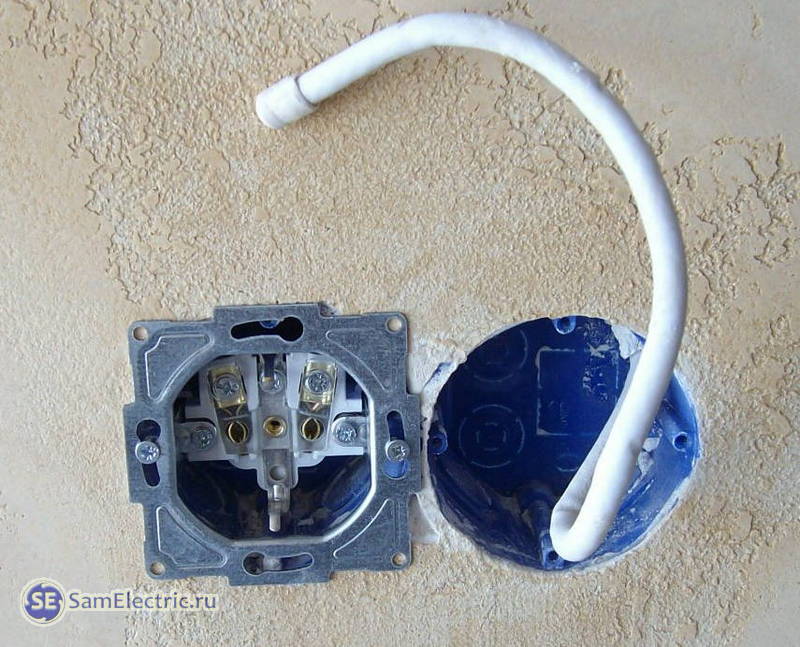
Since the article is about the antenna cable and antenna sockets (sockets for a TV), for example, the photo below shows the installation of wires going to the installation site of the TV - antenna, for the TV socket, and power supply, for the 220V socket.

Not the best best example, and not because of the method of fastening and the quality of the photo, but because it is better not to lay the signal antenna cable and the power cable next to each other in parallel, it is better to make the distance between them at least 3 cm. Although, in modern TVs 50 Hz interference is easily cut off, it’s better to be safe. If you use a high-quality antenna cable with good braiding, this requirement is not very critical.
After completing the second stage, this place for connecting the TV looked like this:

Installation of sockets for the TV - power and antenna.
If you need more 220V sockets (connecting an additional tuner, player, etc.), then the place where the TV is mounted may look like this:
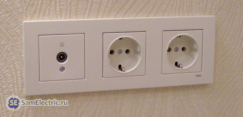
TV socket and 2 power sockets on the Viko wall
Or this, if funds allow:

TV socket and 2 power supplies on the wall Visage deluxe
Well, if there is a lot of equipment, then behind the TV with large diagonal there will be a collection of sockets like this:
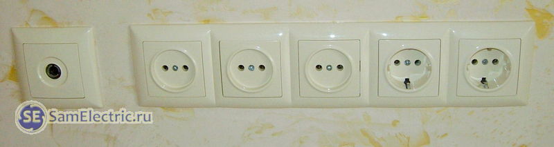
TV socket and 5 power points on Visage wall.
Why on last photo Is the antenna socket separate? It's simple, because there is no frame for 6 points. Although, such an installation makes sense, because it is generally better to conduct a low-current (HF signal) separately from the supply networks.
Connection diagrams for TV sockets
Connecting TV sockets according to the star pattern
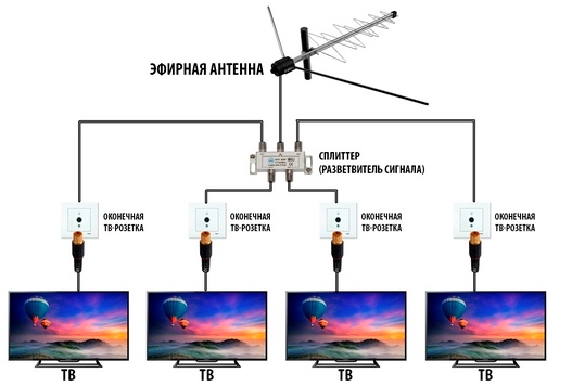
There is only one entrance to the apartment, and there are modern apartment 2-3. To connect two or more TVs, use a special splitter device - splitter, which has one input and 2-3-4 outputs. Then the connection diagram for TV sockets for TVs will be called star:
Connection diagram for TV antenna sockets with a star
It is assumed that a cable with a signal enters the apartment cable television, in which the signal is strong enough. If you want to connect 2 or more TVs, it is better to ask your cable TV provider (or your neighbors) in advance whether the signal strength is enough. The signal level can be raised at your request; usually there is a resource for this. In addition, in some places you have to pay for connecting additional TVs, and for unauthorized additional connection- to pay a fine.
If there are concerns that the power may not be enough, then it is necessary to provide space and power for installing a TV amplifier. It is indicated on the connection diagram with a star and a dash as an optional element. It is best to place the amplifier as close as possible to the signal source - at the entrance to the apartment or, better yet, at the television distribution panel in the entrance.
Star scheme for connecting several TVs to one antenna it is most widely used, as it has the following advantages:
- Cables to all sockets come from one distribution box, which is convenient for installation and maintenance,
- Minimum attenuation of the television signal,
- If one of the signal lines or sockets, the rest are working normally.
The only downside is the high consumption of the antenna cable, which is insignificant, especially with optimal wiring. The peculiarity of this scheme is that the input and output cables should not lie next to each other so that there are no problems with signal quality.

Antenna splitter box. Antenna cable outputs for 3 TVs are at the top. On the side is the antenna input and, in the future, the Internet input. Everything is done with SAT 703 cable. Everything is then plastered, with only a cover on top for access to the splitter.
By the way, the same star connection scheme is used when wiring power supply circuits, and is the most preferable.
Connecting TV sockets using a pass-through design
This connection is also called a connection diagram “ train«.
If the sockets are not shown with a star on the diagram, then they are required in the pass-through diagram. TV sockets in a daisy chain circuit should only be used checkpoints. The last socket in the daisy chain connection must be final.
It is logical that the signal at the input of the first TV will be more powerful than the last one. But you don’t need to worry too much about this. The fact is that the cable television signal level is high enough to support all televisions. When using a high-quality television cable and correct connection(F - connectors) the picture on the screens will be indistinguishable in quality.
In addition, modern televisions have a long-established amplification and automatic signal level control circuit.
Connecting digital television (IPTV)
In addition to connecting to analogue television, many television providers now have the opportunity to connect to digital television. The quality there is much higher. Digital TV connection diagram - star only.
The fundamental differences are that a digital (computer) cable is used, a star connection; instead of a splitter, a digital splitter (router or hub) is used, which has one input and several outputs. One TV is connected to one output. The TV must understand the digital IPTV signal - have a CAM module. If your TV does not receive a digital TV signal, you need a special SD set-top box. In both cases, a smart card is purchased from the provider for charging and managing services.
Check with your provider for digital television(DVB) future. IN apartment buildings In large cities, analog television will last a couple more years.
And the ethereal antennas have already died. Remember, 5-10 years ago all the windows, balconies and roofs of apartment buildings were covered with antennas?
Types of TV sockets
There are three types of TV sockets: pass-through, end and single(simple).
Pass-through TV sockets They have an input, an output (jack for connecting a TV) and another output to the next outlet. Each pass-through socket introduces attenuation into the branch signal, which is approximately an order of magnitude greater than that of the end socket.
Final and simple TV socket - what's the difference?
In a star circuit they use terminal or simple(single) TV sockets. There is no difference between them if a TV is connected to them. If the TV is not connected, then in the case of a simple socket, distortion of the image on the screen in the form of repetitions is possible. This happens because the terminal socket has a line impedance of 75 ohms. But a simple one does not have it, and the resistance in the line is equalized due to the input resistance of the connected TV. It does not matter at all whether the TV is connected to the 220 V power supply or not.
The terminal sockets are structurally designed to have a characteristic impedance equal to the characteristic impedance of the line, 75 Ohms.
Installation and connection of a TV outlet
The photo below shows how to connect a TV outlet with your own hands. In this case, this is the terminal socket. Given step by step photos, installation features depend on the specific design.
Installation boxes for antenna socket and a 220V power socket. 220 socket installed
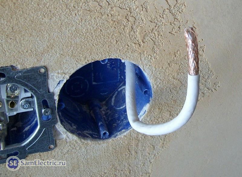
Preparing the TV cable before installing the antenna socket. 2nd stage of cleaning. The latch is pre-attached, but on the wrong side)

Preparing the TV cable before installing the TV socket. Third stage of cleaning

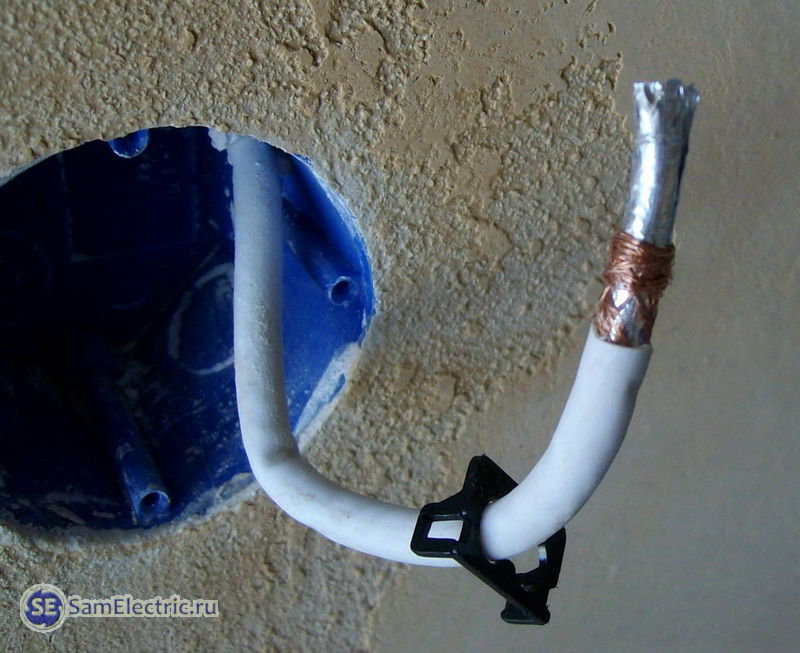
TV cable installation
Installing a TV cable - connecting a socket for a TV cable. Step 2

Installing a TV outlet - final installation of the cable. The black latch is now seated correctly

We carefully roll up the excess length of the cable without sharp bends. Could have left less.
That's it, all that remains is to put on the frame
Installing a TV outlet. Repeat of the photo shown at the beginning of this article
Below is another option for installing sockets for a TV. It’s clear that it’s better to hide everything behind the TV, isn’t it?
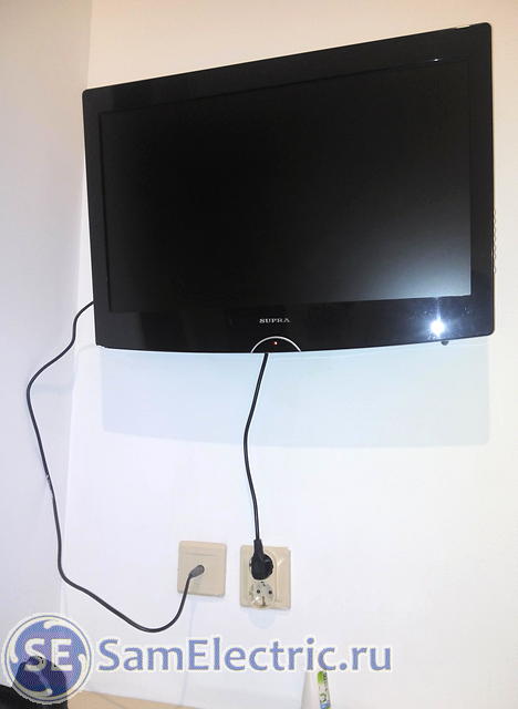
TV sockets - installation option
Antenna socket device
And finally - photographs of the terminal socket in disassembled form.


That's all I wanted to tell you about installation of TV sockets. If anything is not clear or you have something to add, ask and write in the comments. If you are interested in what I will publish next on the SamElectric blog, subscribe to receive new articles.
P.S. I consulted Legrand salespeople by phone about the difference between simple and terminal TV sockets. They said the following. " Terminal sockets are used together with pass-through sockets, and simple sockets are used if with a splitter.” To be honest, I cannot confirm the information, since I have always installed only passing and end ones. And when asked about simple TV sockets, sellers look surprised and say that such things have never been on sale. All the better.
 (1 ratings, on average: 5,00 out of 5)

