Terminology solidly grounded neutral - document
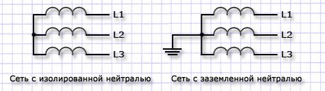
Consumer power sources are generators or power transformers. Usually three-phase windings join in a star. The common point of this connection is called the neutral point. If it is directly or through a small resistance (current transformer) connected to the ground loop directly at the power supply, then this is - solidly grounded neutral.
The operation of the neutral with grounding is only one of the possible modes of its operation. Depending on the operating conditions of the network in case of single-phase earth faults, the required methods of protecting people from electric shock, methods of limiting surges, other modes are also used:
- with ungrounded (isolated) neutral;
- with compensated (resonantly grounded) neutral;
- with effectively grounded neutral.
These modes are typical for electrical installations with a voltage of 6 kV and above. An isolated neutral system is also used at voltages up to 1000 V, but not as widely as grounded. She provides high security when operating mobile electrical installations, mining enterprises, where the use of a ground loop to ensure electrical safety is unreliable or inefficient.
Installation in the neutral conductor of compensation installations allows to reduce the capacitive earth fault current of electrical installations above 1000 V. Compensation is carried out due to smoothly or stepwise variable coil inductance. At the earth fault point, the current at full compensation becomes zero. In addition, resistive neutral grounding is used for effective protection operation. It creates an active component of the current, to which the relay of the cell that feeds the damaged line reacts.
Effective neutral grounding is used on power lines with a voltage of 110 kV and above.
All domestic, rural, country electrical networks are powered by transformer substations with a solidly grounded neutral. Therefore, we will consider the features of its work in more detail.
The design of networks with dead-earthed neutral
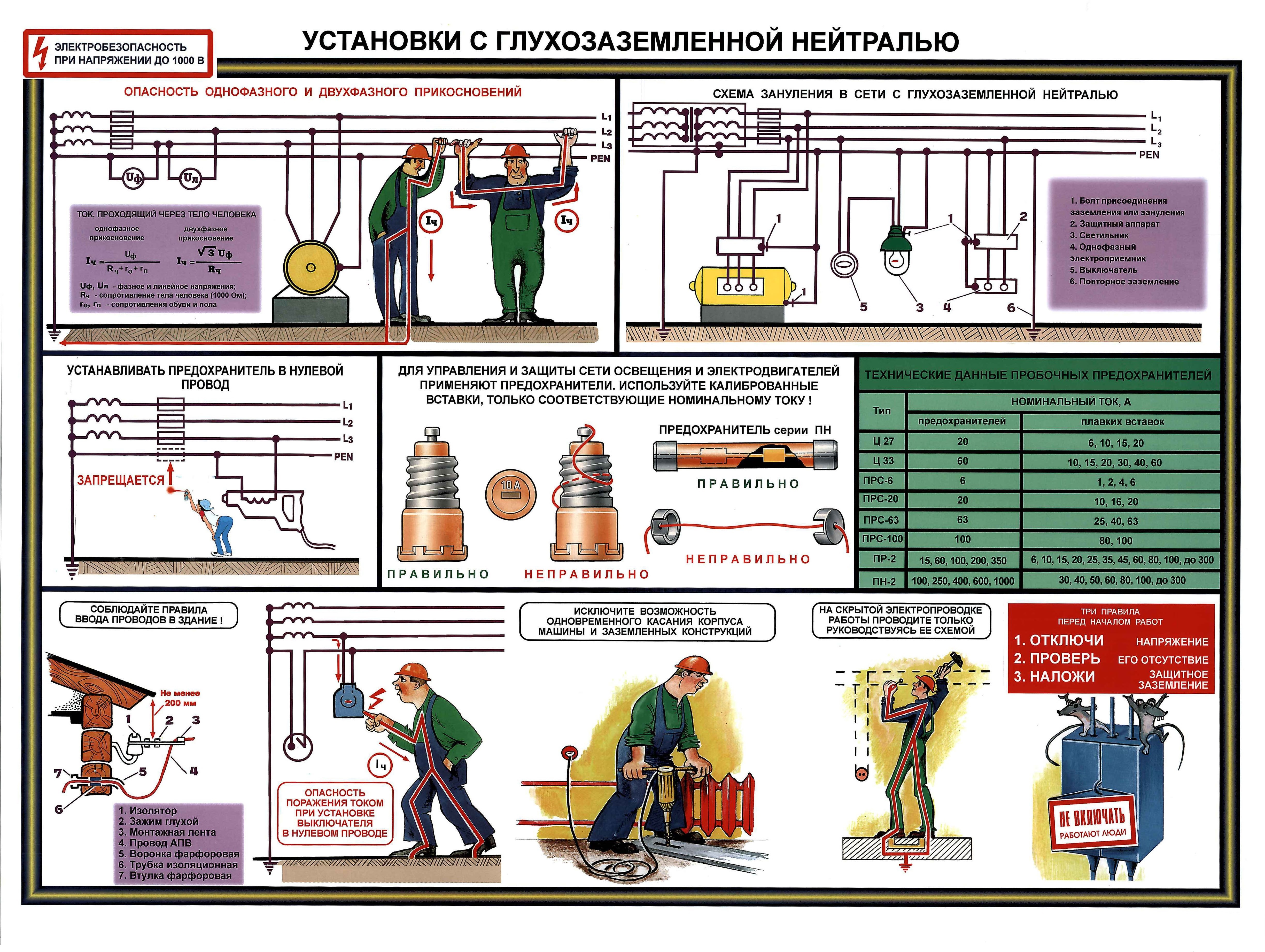
Transformers and generators used for these electrical installations have three phase power outputs and one neutral (zero). The voltage between the phase terminals is called linear, and between any phase and zero output - phase. The line voltage determines the rated voltage of the entire electrical installation. It can take standard values of 220 V, 380 V and 660 V. The line voltage in household networks is 380 V.
The phase voltage is less than the linear voltage by √3 times, which corresponds to 127, 220 and 380 V. At a linear voltage of 380 V, the phase voltage is 220 V.
Thus, a 380 V network with a grounded neutral is suitable for power supply three-phase consumers for a voltage of 380 V and single-phase for a voltage of 220 V. Single-phase loads are connected between the phase and neutral conductors and are evenly distributed over the phases.
The substation where the power transformer is installed has a ground loop: steel or copper parts connected in a certain way, buried in the ground. The geometric dimensions of the ground loop are calculated so that they effectively contribute to the spreading of a single-phase fault current over the ground. The ability of a grounding device to conduct this current is quantified by its spreading resistance. Permissible values of this parameter are regulated by the PUE. For transformer substations, the resistance of the ground loop should not exceed 4 ohms at a rated voltage of 380 V.

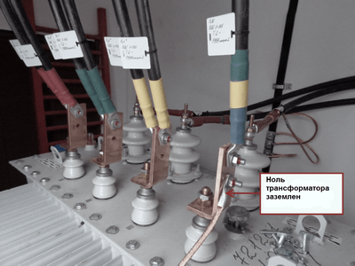
The conclusions from the ground loop at the substation are connected to the neutral bus - the metal strip of the switchgear, to which the conductor from the zero terminal of the transformer is also connected. Corresponding cores of outgoing cables are connected to the same bus. Phase conductors are connected to the terminals switching devices: knife switches, automatic switches, contact pads of fuse holders.
Cable lines extending from the substation are made with four-core cables. In electrical installations built earlier, there are three-core cables with an aluminum sheath, which is used as a neutral conductor.
The electrical installations of the consumer for inputting the supply voltage have an input switchgear (ASU). It also contains a zero bus, like a substation. Zero wires of supply and outgoing wires are connected to it. cable lines. The ASU has a re-ground loop, which is also connected to the neutral bus.
Protection of people from electric shock in a network with a solidly grounded neutral
Now let's move on to a direct explanation of why the transformer neutral is grounded and how it works.
Theoretically, for any point in the electrical network, the potential of the neutral conductor relative to the ground is zero. The re-grounding circuit at the consumer makes this equality even more durable, especially if the supply substation is far away.
Electric shock to people is possible in the following cases:
- Violations of insulation inside electrical equipment when its case is energized;
- Violations of the insulation of wires and cables, when the metal structures on which they are laid are energized;
- Violations of the insulation of live parts or breakdown of electrical equipment, when potential zones are formed on the surface of the earth or floor that are dangerous for people passing by (step voltage);
- Errors during repair and operation, leading to direct contact with electrical equipment components that are under phase voltage.
To eliminate the situations described in paragraphs 1 and 2, all cases of electrical appliances and metal structures are connected to the ground loop. At enterprises, for this, a steel strip is laid along the perimeter of rooms with electrical equipment, to which all metal parts are attached. So their potential is forcibly equated with the potential of the earth.
In the event of a short circuit of the phase conductors to the case grounded in this way, even if the protection fails, the fault current will flow through the ground conductors to the ground loop. The resistance relative to the earth of the body of a person who touches the emergency building is much greater than the resistance between the earth and the body. Therefore, a current exceeding dangerous values \u200b\u200bis not going through the human body.
The second principle of protection is the quick shutdown of the emergency mode. After all, the current will not just go to the circuit, it will go towards the neutral of the transformer. A short circuit is organized, the current of which has great importance. Protective equipment will successfully respond to it: a fuse or a circuit breaker. The accident will be eliminated almost instantly, the damaged section will be turned off.
Now let's move on to point 3 and step voltage protection. To lying on the wet concrete floor it is dangerous to approach a bare wire. The life-threatening potential ripples out from him like circles on water. If your feet are on areas of the floor with different potentials, you can also get an electric shock.
If such a situation is possible indoors, a potential equalization system is arranged inside the floor: a metal mesh is immured. The grid is connected to the ground loop in several places. Thus, the legs of a passer-by are shunted by the metal bars of the lattice, most of current will go past it.
Classification of grounding systems according to PUE
The grounding scheme described above is designated TN-C. The conductor connecting the dead-earthed neutral with consumers is called combined, as it serves both to transfer the load current and to connect the electrical equipment cases to the ground loop. It bears the abbreviation PEN.
On this universality, the main drawback of such a system looms. When zero load current passes through the PEN conductor, a potential difference is formed. This is especially true for unbalanced phase loads. Bottom line: the potential on the electrical equipment cases may differ from the ground potential.
In electrical installations, especially old ones, breaks in the PEN conductor are theoretically possible. At the same time, there may be a potential on it relative to the ground phase voltage. This regime poses a threat to human life.
There are technical difficulties with the grounding of cases household electrical appliances connected to the TN-C system.
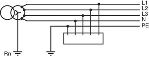
To remedy these shortcomings, the TN-S system. In it, the protection and switching functions of the operating current are divided between two neutral conductors. The working current conducts the zero working conductor - N, and the zero protective PE serves to connect the housings to the ground loop. 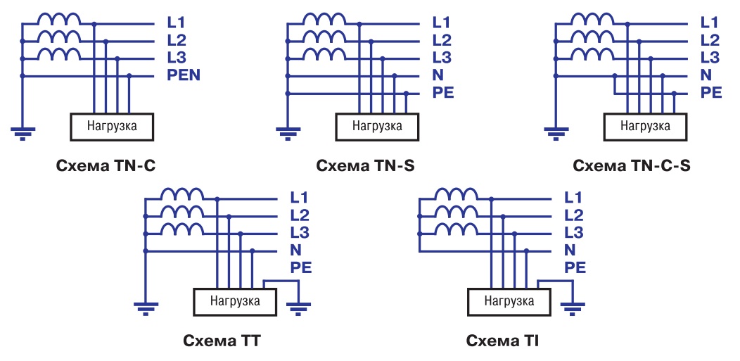
The separation of PEN into N and PE occurs directly at the substation where the neutral is grounded. But when modernizing and reconstructing electrical installations, this can be done in any switchgear. In this case, the entire circuit as a whole is called TN-C-S. A re-ground loop is required at the separation point.
Networks with an isolated neutral according to the PUE are designated IT. It does not have conductors for connection with the ground loop of the supply substation. The consumer arranges his own ground loop.
There is a TT system that also has a solidly grounded neutral. Unlike TN systems, it has only a zero working conductor. Zero protective to the consumer comes from its own grounding device.
Production, transformation, transportation, distribution and consumption of electrical energy is carried out through a symmetrical three-phase wire system. The symmetry of the system is achieved by the equality of phase and linear voltages, uniform loading of all phases by current, the same phase shift of voltages and currents.
However, during operation, symmetry violations are inevitable. three-phase system, which can be caused by: wire breakage, insulation breakdown, overlapping on foreign objects, non-switching of phases of switching devices, etc.
In any case, unbalance leads to the appearance of negative and zero sequence currents, as well as the aperiodic component of the currents, which can be dangerous for the safety of the equipment. Therefore, the asymmetry must be corrected as soon as possible. The operating mode of the neutral network has a significant influence on the speed of relay protection in open-phase modes.
There are several modes of neutral operation: isolated, deaf-earthed And effectively grounded. Each mode has its own advantages and disadvantages. In networks with voltages up to 35 kV inclusive, an insulated neutral is used. This means that the middle point of the HV windings of the transformer is not connected to earth.
A single-phase earth fault with such a power supply system does not lead to an emergency shutdown of a damaged line, since the earth fault current is rather insignificant, its value is due only to the capacitance of two undamaged phases relative to earth. The current of a single-phase earth fault, in networks up to 35 kV, is not able to maintain the arc.
In the event of a metallic short circuit of one phase (“full earth”), the voltage on the other two increases to linear, but the power supply to consumers is maintained in the remaining two phases. For the safety of transformers under such operating modes, the insulation of its neutral is performed for the voltage class corresponding to the insulation of the linear inputs.
With significant capacitive line currents up to 35 kV, arc-suppressing coils are used, connected to the neutral of the transformers. Arc quenching is provided by the inductance of the coil, which compensates capacitive current ground fault.
Power supply system with effectively earthed neutral a network is considered in which part of the neutral windings is grounded power transformers. A single-phase short circuit, in such networks, leads to the disconnection of the damaged section.
The short-circuit current flows from the fault to the nearest grounded neutrals transformers on the ground, distributed in accordance with the resistance of the loop phase - zero. To transformers, the neutrals of which are not grounded, the short-circuit current (hereinafter - short circuit) does not flow.
Considering the fact that for all types of damage in electrical networks, 80% of the damage falls on single-phase short circuits, and the fact that close single-phase short circuits. have significant currents, they try to limit their influence.
To do this, some of the neutrals in the network are left ungrounded, thereby increasing the resistance of the circuit loop and limiting single-phase short-circuit currents. The total balance of grounded and ungrounded neutrals is calculated based on the conditions for the selective operation of relay protection devices and the limitation of short circuit currents.
Besides, important condition when choosing grounding points, there is a condition for limiting overvoltage on neutral windings in case of asymmetric damage. On power equipment, the neutral insulation class is usually taken one voltage class lower than the rated voltage of the HV windings. This practice allows you to save on insulation and equipment dimensions, which gives a high economic effect.
However, on the other hand, the reduced level of neutral insulation leads to the need to use equipment that would limit overvoltages and currents in the neutral terminal. Surge suppressors can be used as protection against short-term overvoltages; current-limiting reactors and capacitors are used to limit currents.
In the deaf grounding mode, networks with a domestic consumer work. With this mode of operation of the neutral, the middle point of the LV windings of the transformer is connected to the ground loop. In switchboards of residential buildings, the housing of the shields is also connected to the ground loop.
So, two wires “enter” into each apartment or house: phase and zero - thereby providing the consumer with a voltage of 220 V. If the insulation is damaged phase wire, and touching it to grounded structures, the damaged section of the network is immediately disconnected. concrete walls and floors in apartment buildings, also have ground potential.
The short-circuit current has sufficient values for the operation of protective switching equipment. IN Lately, to increase the level of electrical safety, in addition to the working zero, a protective grounding conductor is also brought into the living quarters, which is connected to the housings of electrical appliances. The protective earth wire in the shield is also connected to grounded structures.
It should be noted that autotransformers of any voltage class always operate with a solidly grounded neutral. The insulation of the MV windings of the autotransformer is made based on the value of the typical power, which is less than the nominal one, which means that the insulation level is reduced. This, in fact, is the economic advantage of an autotransformer over a transformer.
With open-phase switching of autotransformers, dangerous overvoltages occur in the electromagnetic system, which can be limited by dead grounding of the zero output.
Based on the foregoing, we can conclude that the mode of operation of the neutral has a significant impact on the reliability of power supply and the mode of operation of the power system as a whole.
Modern human life, its comfort and provision with everything necessary, are inextricably linked with electricity. Thanks to him, a person has a livelihood and the opportunity to influence the forces of nature in order to extract the maximum benefit for his life. But in addition to the many advantages that electricity has, there is one huge minus - devices and equipment that consume and generate electricity pose a threat to human life if you do not follow the rules for their use.
Electrical installations and their classification according to safety requirements
The main factors affecting the degree of danger to human life in electrical installations of any type are:
- voltage;
- type of neutral grounding;
- the value of the current closed to the ground;
- insulation of parts through which current flows;
- resistance of the human body;
- earth (soil) resistance in the coverage area electric current.
Based on these main sources, in the current "Electrical Installation Rules" (PUE), all installations are divided into four categories.
The first group consists of installations with solidly grounded neutral of transformers operating from 220 kV and above, and with effectively grounded neutral - installations from 110 to 220 kV. The effectively earthed neutral is a circuit by which the earth fault current is limited, it may contain different kinds resistances (active, non-linear and reactive), as well as an ungrounded neutral.
The second includes installations where it is used isolated neutral or its resonant grounding with the help of arcing resistors and reactors operating in networks whose voltage ranges from 3 to 35 kV.
The third is electrical installations that use a network with a solidly grounded neutral and operate under voltage from 110 to 600 V. In these installations, earth fault currents are large.
Safe operation of electrical installations
It is impossible to completely exclude factors that threaten the health and life of people working at electrical installations, because they have a natural background. But to reduce them to a minimum and make work in installations as safe as possible is not only possible, but also necessary. To do this, all work on the maintenance and operation of electrical installations is regulated in a single collection of rules and regulations: "Rules for the installation of electrical installations" (PUE). One of essential requirements PUE is the protective grounding of electrical installations. It is this requirement that will be discussed in more detail in this article.
Protective grounding is designed to protect the personnel working and maintaining these installations and networks, as well as consumers of electricity using it in household appliances and devices. What does protective earthing provide? Human safety in case of accidental contact with metal parts of electrical installations that are not current-carrying, but are energized due to the breakdown of the insulation of live conductors.
What is grounded in electrical installations?
The requirements and rules for the use of protective grounding are summarized in a single document that regulates and defines the standardization of the entire process - GOST. Grounding, which ensures the protection of personnel and consumers from, is carried out strictly in accordance with PUE requirements and the corresponding GOST. Protective grounding of electrical installations provides for the electrical connection of the metal parts of electrical installations with the ground, and in the absence of it, with a conductor that replaces the ground. It should also be noted that those parts of installations that no longer have any other protection are grounded.
Thus, metal cases of electrical units, devices, machines, lamps, sockets and switches, as well as cable and wire armor are grounded.
Existing grounding systems for electrical installations
Protective grounding systems of electrical installations are determined on the basis of such characteristics of the power source as dead-earthed neutral, isolated neutral. There are three main systems developed by the International Electrotechnical Commission (IEC): TN, IT and TT. Let's consider them in more detail.
TN system and its subsystems
Systems with a solidly grounded neutral, in which the metal parts of the electrical installation are connected to the neutral using zero ground conductors, belong to the TN group. In turn, this group has subgroups that are formed by using the zero working and protective conductors. So, if these conductors are combined in one wire along the entire length of the network, the subsystem is designated TN-C. This is the old Soviet system. If protective and working neutral wire are combined only in the section of the circuit starting from the power source ( transformer substation), then this is already a TN-C-S subsystem. Well, in the case when the zero working and protective wires are separated by separate wires throughout the network, this subsystem is designated TN-S. It is considered more preferable for the overall safety of the electrical installation.
IT and TT systems

A system in which there is no neutral earthing or it is made through resonant earthing is designated as IT. In such a system, metal parts of electrical equipment are grounded by separate conductors connected to grounding devices.
A solidly earthed system in which metal parts of electrical equipment are earthed using devices not connected in any way to the neutral of the power supply is designated TT and is used exclusively for mobile premises. In other cases, such a system requires the use
Grounding devices
According to the PUE, to protect a person from dangerous voltages, a grounding circuit is used, mounted by electrical connection installation parts made of conductive materials and insulated from live parts, with a ground electrode. In turn, the grounding conductor is a conductor made of metal, which has good electrical conductivity and a large area of contact with the soil. All together - a grounding conductor and wires that electrically connect it with parts of electrical installations and there is a grounding device.
Depending on the type of current used in electrical installations up to 1000 V, grounding schemes are used with a solidly grounded neutral or isolated ( alternating current), solidly grounded or isolated midpoint (direct current). The neutral of the power source (generator or transformer) is called dead-grounded if it is connected directly to the grounding device, and the neutral that is not connected to it or connected through devices with high resistance is considered isolated.
Types of grounding devices
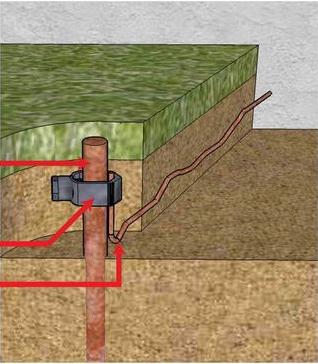
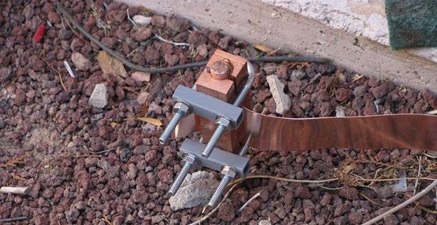
Ground electrodes are divided into two types: artificial and natural. The first type of grounding structures involves the use of various metal objects. They can be corners, rods and pipes, having a length of at least two and a half meters and buried (dug) in the ground. Between themselves, they are connected by strips of steel or pieces of metal wire - wire rod - of large diameter (at least 8-10 mm) by welding. Grounding conductors can be both metal and copper tires, and copper wire bundles connected to parts of electrical equipment either by welding or by bolting.
The second type of grounding structures involves the use of building structures made of metal and reliably connected to the ground as a grounding conductor. All reinforced concrete structures must have metal mortgages for connecting grounding conductors. In this case, the grounding conductors are no different from the conductors used in artificial grounding conductors.
Another type of grounding device is zeroing. This type of protective grounding consists in connecting parts of electrical installations isolated from current with a dead-earthed neutral through a neutral wire. Zeroing ensures the occurrence of a short circuit in case of any phase closure to the device case and allows the protective shutdown equipment to operate more efficiently.
Requirements for grounding devices
All devices used for grounding must comply with the standards approved by the state, building codes and PUE. Their task is to ensure the safety of people, the protection of electrical installations and their modes of operation.
In no case are several parts of the electrical installation allowed to have grounding conductors - each part must correspond to only one grounding cable having a cross-sectional diameter not less than that specified in the PUE. Grounding conductors, placed openly, are protected from the effects of an aggressive environment by painting them black.
The technical condition of the grounding devices and checking the grounding is carried out by inspecting the visible part of the device with the naked eye, inspecting with partial opening of the soil and measuring the parameters of the grounding device. Visible part devices are inspected once every six months.
Requirements for connections of protective and grounding conductors
All connections of the grounding conductor and grounding conductors are made by welding. Cases of electrical installations, machines and devices, the main grounding contact on the ground loop and high-voltage line supports are connected with a bolted grounding conductor. Grounding conductors are made of steel or copper tires, as well as copper bundles. An earth cable can also be used as ground conductors. For these purposes, both stranded and single-core copper are used, which allow low-resistance connections.
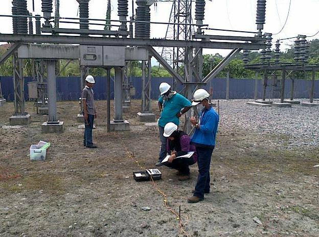
Measuring the resistance of earthing devices

To make sure that the resistance of the existing grounding device complies with the requirements of the rules and regulations, measurements of the existing resistance are carried out. The task of such a measurement is to determine the resistance value of the grounding system to the current passing through it to the ground - the so-called spreading current.
Measurements are carried out in accordance with the required safety standards: avoidance of single-phase short circuit and use of personal protective equipment, including dielectric gloves and boots, as well as insulating tools.
Equipment and means for measuring earth resistance
The main instrument used to measure the resistance to spreading currents is the IS-10 grounding meter. This device operates in five measurement ranges, which explains its wide application. The minimum range is resistance from 0.01 to 9.99 ohms, followed by ranges of 0.1-99.9 ohms, 1-999 ohms, 0.01-9.99 kOhm. The maximum resistance determined by this device is in the range from 1 to 999 mΩ. Remote current and potential electrodes are used in combination with the instrument for measurements.
It should be noted that measuring circuit grounding is assembled according to strict rules - the connecting conductors of the device, first of all, to the current and potential electrodes, then to the device and, lastly, to the ground electrode.
Grounding Test Methods
The amount of resistance to spreading current for different grounding devices is not the same and depends on many factors, such as the type of electrical installation, the condition of the soil at the installation site of this installation, and the type of such device used.
The measurement technique contains two methods, which are displayed in the rule that is valid for IS-10 devices when they measure the ground resistance. If the resistance of the device specified in its passport is higher than 5 ohms, a three-wire circuit is used. If the values are less than this value, a four-wire circuit is used.
In electrical installations with a dead-earthed neutral up to 1 kV, when it is not possible to ensure electrical safety only with the help of a protective automatic power off, re-grounding is carried out.
Re-grounding is a deliberate connection in electrical installations up to 1 kV of zero protective conductor(PE) circuit to an earthing device that is electrically connected or not connected electrically to the earthing device of the power supply.
PUE-7 p. 1.7.61
Re-grounding of electrical installations with voltage up to 1 kV, powered by overhead lines, must be carried out in accordance with 1.7.102-1.7.103. The term “Recommended” means that if there is a main potential equalization system to which structures used as natural ground electrodes are connected, then re-grounding is provided by these natural ground conductors and the electrical installation of an artificial ground conductor is optional. Re-grounding should be performed on overhead lines and branches from them in accordance with PUE-7, clause 1.7.102 and clause 1.7.103
PUE-7 p. 1.7.102
PUE-7 p. 1.7.103
1.7.103. The total spreading resistance of ground electrodes (including natural ones) of all re-groundings of the PEN conductor of each overhead line at any time of the year should be no more than 5, 10 and 20 Ohms, respectively, at line voltages of 660, 380 and 220 V of the source three-phase current or 380, 220 and 127 V source single-phase current. In this case, the spreading resistance of the grounding conductor of each of the repeated groundings should be no more than 15, 30 and 60 ohms, respectively, at the same voltages. At resistivity earth ρ > 100 Ohm⋅m, it is allowed to increase the indicated norms by 0.01ρ times, but not more than tenfold.
Re-grounding wiring is performed to reduce the contact voltage on open conductive parts (metal cases of electrical equipment, etc.), as a result, the risk of electric shock is reduced in case of single-phase ground faults, on open or third-party conductive parts.
Re-grounding is installed in order to prevent the introduction of induced potentials into the electrical installation of the building through external communications entering the building and to reduce the potential brought to the grounded housings of electrical receivers when the zero working conductor of the supply line is broken.
If re-grounding is installed, then when a separate electrical receiver is shorted to the case, the short-circuit current passes not only through the neutral protective conductor, but also partially through the ground through the resistance of the grounding conductors of the power source and re-grounding. As a result, the voltage relative to the ground on the body of the damaged electrical receiver decreases, and the neutral voltage of the power source rises. The ratio of these voltages is proportional to the ratio of the resistances of the corresponding ground electrodes.
In the distribution networks of cities, factories and industrial enterprises distribution scheme electrical potentials much more difficult, since several electrical installations are often fed from one transformer, where they are used for re-grounding natural ground electrodes, the resistance of which is practically impossible to take into account by calculation. Therefore, in accordance with PUE-7 clause 1.7.61, during electrical measurements, the resistance of the grounding conductor of re-grounding is not standardized.
PUE-7
1.7.61. When using the TN system, it is recommended to re-ground the PE and PEN conductors at the input to the electrical installations of buildings, as well as in other accessible places. For re-grounding, natural grounding should be used first. The resistance of the re-grounding earth electrode is not standardized. inside the big and multi-storey buildings a similar function is performed by potential equalization by connecting a zero protective conductor to the main ground bus.
Re-grounding of electrical installations with voltage up to 1 kV, powered by overhead lines, must be carried out in accordance with 1.7.102-1.7.103.
For stand-alone electrical receivers outdoor installation, as well as for buildings or structures with metal case in the immediate vicinity of them, re-grounding also performs the function of equalizing the potentials between the conductive parts of these structures accessible to the touch and the ground, and also reduces the possible values of step voltages.
Inside buildings, land is usually not available. The danger of electric shock during single-phase short circuits under these conditions is determined by the value of the potential difference between the conductive parts that are simultaneously accessible to touch, to reduce which it is necessary to carry out potential equalization on the basis of PUE-7, clauses 1.7.82 and 1.7.83.
PUE-7
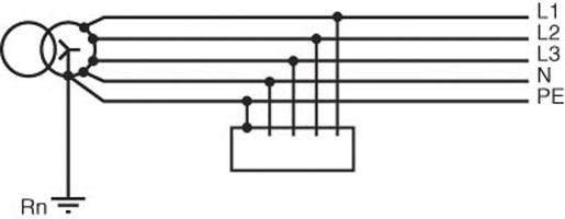
1.7.82. The main potential equalization system in electrical installations up to 1 kV must interconnect the following conductive parts (Fig. 1.7.7):
- zero protective PE or PEN conductor of the supply line in the TN system;
- grounding conductor connected to the grounding device of the electrical installation, in IT and TT systems;
- grounding conductor connected to the re-grounding conductor at the entrance to the building (if there is a grounding conductor);
- metal pipes of communications included in the building: hot and cold water supply, sewerage, heating, gas supply, etc. If the gas supply pipeline has an insulating insert at the entrance to the building, only that part of the pipeline that is relative to the insulating insert from the side of the building is connected to the main potential equalization system;
- metal parts of the building frame;
- metal parts of centralized ventilation and air conditioning systems. In the presence of decentralized ventilation and air conditioning systems, metal air ducts should be connected to the PE bus of power panels for fans and air conditioners;
- grounding device of the lightning protection system of the 2nd and 3rd categories;
- grounding conductor of functional (working) grounding, if there is one and there are no restrictions on connecting the working grounding network to the protective grounding grounding device;
- metallic sheaths of telecommunication cables.
Conductive parts entering the building from the outside should be connected as close as possible to their point of entry into the building. To connect to the main potential equalization system, all of these parts must be connected to the main grounding bus (see 1.7.119-1.7.120) using the conductors of the potential equalization system.
PUE-7 p. 1.7.83
1.7.83. The system of additional potential equalization must interconnect all open conductive parts of stationary electrical equipment that are simultaneously accessible to the touch and third-party conductive parts, including metal parts accessible to touch. building structures building, as well as neutral protective conductors in the TN system and protective earth conductors in IT and TT systems, including protective conductors socket outlets. For potential equalization, specially provided conductors or open and third-party conductive parts can be used if they meet the requirements of 1.7.122 for protective conductors with respect to conductivity and continuity of the electrical circuit.
PUE-7 p. 1.7.122
1.7.102. At the ends of overhead lines or branches from them with a length of more than 200 m, as well as at the inlets of overhead lines to electrical installations, in which, as a protective measure in case of indirect contact, automatic shutdown supply, re-grounding of the PEN conductor must be performed. In this case, first of all, natural grounding should be used, for example, underground parts of supports, as well as grounding devices designed for lightning surges (see Chap. 2.4). The indicated repeated groundings are performed if more frequent groundings are not required under the conditions of lightning surge protection. Re-grounding of the PEN conductor in networks direct current must be made using separate artificial grounding conductors, which should not have metal connections with underground pipelines. Grounding conductors for re-grounding the PEN conductor must have dimensions not less than those given in Table. 1.7.4.
The main task of re-grounding the zero protective conductor is to reduce the voltage on open conductive parts and in the event of its breakage. The most dangerous case is a break in the neutral conductor with single-phase short circuit on the body (ground) behind the place of the break. In this case, in the absence of repeated grounding, the voltage on the cases of all power receivers behind the break point will be close to phase for a long time, since such damage cannot be automatically turned off by protection devices.
A network circuit with a solidly grounded neutral serves to protect a person from electric shock. In emergency cases, a dead-earthed neutral equalizes the potentials, as a result of which a person touches metal parts electrical equipment becomes safe.
The protective device will also play a role in emergency situations by turning off the power supply, since during short circuits, the current in the network increases.
Device and principle of operation
Consumer nutrition electrical energy produced by power transformers and generators. Most often, the windings of the three phases of these devices are connected according to the star scheme, in which common point is neutral. If this neutral is connected to ground through a low resistance, or directly, directly near the power source, then it is called a solidly grounded neutral.
Other modes of operation of the neutral with grounding are also used, depending on the modes of operation of the network during ground faults, the necessary methods for protecting a person from electric shock, methods for limiting overvoltages:
With effectively earthed neutral.
With ungrounded neutral.
Compensated neutral.
These modes are used for electrical devices 6 kilovolts or more. used up to 1 kV, and has not found wide application. It does safe work only mobile devices in which it is impossible to make a ground loop.
Installation of compensation devices on the neutral makes it possible to reduce the capacitive short circuit current of devices operating with a voltage of more than 1 kV. Compensation is made using inductors, as a result of which the current at the fault point becomes zero. For effective work protection, neutral grounding with a resistor is used. It forms active part current on which the protective relay acts.
A solidly grounded neutral is the most effective way protect people from electric shock. It is used in most electrical networks nutrition. The voltage between phases is called linear, and between phase and zero - phase. Rated voltage electrical installation is determined by linear value voltage. It can be 220, 380, 660 volts. In household power networks, the voltage is 380 volts.
Single-phase consumers are connected between phases and zero evenly. at the substation has a ground loop. It includes metal parts interconnected and buried in the ground. The dimensions of the circuit are determined taking into account the effective distribution of current along the ground during a short circuit.
The operability of grounding is determined by the value of current spreading resistance. Permissible values of this parameter are specified in the rules of electrical installations. For electrical substations, ground resistance should not exceed 4 ohms at a voltage of 380 volts.
The ground loop is connected to a neutral bus made in the form of a metal strip. The neutral wire of the transformer is connected to it. Also, cable cores are connected to it, which go to consumers. The phases are connected to circuit breakers, fuse contacts.
The step voltage acts as follows. If an uninsulated live conductor lies on a wet concrete floor, it is very dangerous to approach it. Tension moves away from him in waves, like circles on water. If a person's feet enter this zone, an electric shock occurs.
To protect people from step voltage, they build in the floor of the room metal mesh, which in different places connected to the ground loop. In this way, the legs of a person are shunted with metal fittings of the grid, and the main part of the electric current passes by the person.
PUE requirements
Ground must be connected to the device with a special conductor. To shorten the path of the flow of electric current and reduce costs, select a place directly next to a voltage source, such as a transformer. There is a limitation that if the ground electrode is the existing concrete foundation, then to the reinforcement concrete base made of metal, the connection is made in two or more places.
A similar number of connections are made to metal frames, which are located deep in the ground. Under such conditions, the grounding system is able to effectively protect a person from unpleasant situations.
If transformers located on different floors of the building act as power sources, then the connection to the neutral is made separate wire which is connected to metal frame the entire building.
The ground connection circuit must not contain fuses, fuses and other components that can break the continuity of this circuit. They also take auxiliary measures that prevent mechanical damage.
Some PUE restrictions
If it is installed on the working, protective or neutral conductors, then the ground electrode wire is mounted immediately after this device, to the neutral conductor.
The resistance of the grounding device in the 220 volt network is limited to the maximum value of 4 ohms, with the exception of the special properties of the earth, which create an increased resistance of more than 100 ohms per meter.
on overhead transmission lines, grounding is installed at the end and at the input of the line for duplication of grounding. This enables efficient operation protective devices. This rule is used when there is no need for installation a large number devices that can eliminate overvoltage during lightning strikes.
When choosing conductors for a grounding device, it is necessary to apply the standards for the smallest allowable dimensions and material of conductors used for re-grounding laid in the ground. For example, if a steel corner is used, then its wall thickness must be at least 4 mm. The total cross-sectional area for ground wires connected to the main bus, in accordance with clause 1.7.117 of the PUE, must be:
10 mm 2 - copper wire.
16 mm 2 - aluminum conductor.
75 mm 2 - steel conductor.
The electric machine installed for protection must have a response speed at short circuit more than 0.4 s at 220 volts.
IN home network according to clause 7.1.36 of the Electrical Installation Code, it is required to lay a network to consumers from common shields with three conductors: phase, working zero and protective ground (grounded neutral). However, in many apartments this requirement is often violated, which is confirmed by the absence of a grounding contact in the sockets.
old regulatory requirements for domestic buildings were determined for insignificant capacities. Today, the power of household electrical devices has increased significantly. The apartments have air conditioners. hobs, ovens which have higher power.
To improve the effectiveness of protection in modern apartments a prerequisite is the presence of grounding. In new housing constructions, a dead-earthed neutral is already included in standard projects. In old buildings, good owners install grounding during major repairs.
 (1 ratings, on average: 5,00 out of 5)

